ORDER NO.
PIONEER CORPORATION 4-1, Meguro 1-chome, Meguro-ku, Tokyo 153-8654, Japan
PIONEER ELECTRONICS SERVICE, INC. P.O. Box 1760, Long Beach, CA 90801-1760, U.S.A.
PIONEER EUROPE NV Haven 1087, Keetberglaan 1, 9120 Melsele, Belgium
PIONEER ELECTRONICS ASIACENTRE PTE. LTD. 253 Alexandra Road, #04-01, Singapore 159936
PIONEER CORPORATION 2001
c
DV-444
RRV2490
T ZZE JULY 2001 Printed in Japan
DVD PLAYER
THIS MANUAL IS APPLICABLE TO THE FOLLOWING MODEL(S) AND TYPE(S).
Type
Model
Power Requirement
Region No.
Remarks
DV-444
DV-440
KUXQ
AC120V
1
KCXQ
AC120V
1
KUXJ
AC120V
1
KCXJ
AC120V
1
DV-440
1. SAFETY INFORMATION ....................................... 2
2. EXPLODED VIEWS AND PARTS LIST ................. 3
3. BLOCK DIAGRAM AND SCHEMATIC DIAGRAM ... 10
4. PCB CONNECTION DIAGRAM ........................... 33
5. PCB PARTS LIST ................................................ 43
6. ADJUSTMENT ..................................................... 48
CONTENTS
7. GENERAL INFORMATION ................................ 54
7.1 DIAGNOSIS .................................................. 54
7.1.1 SELF-DIAGNOSTIC FUNCTION OF
PICKUP DEFECTIVE ........................... 54
7.1.2 TEST POINTS LOCATION ................... 55
7.1.3 TEST MODE SCREEN DISPLAY ........ 56
7.1.4 TROUBLE SHOOTING ........................ 60
7.1.5 ERROR CODE ..................................... 61
7.1.6 DISASSEMBLY .................................... 65
7.2 PARTS .......................................................... 71
7.2.1 IC .......................................................... 71
7.2.2 FL DISPLAY ......................................... 93
8. PANEL FACILITIES AND SPECIFICATIONS .... 94
Î
8
7
¡¢
41
STANDBY/ON
0
3
DVD PLAYER
FL DIMMER
· DV-444
2
DV-444, DV-440
1. SAFETY INFORMATION
This service manual is intended for qualified service technicians ; it is not meant for the casual do-it-
yourselfer. Qualified technicians have the necessary test equipment and tools, and have been trained
to properly and safely repair complex products such as those covered by this manual.
Improperly performed repairs can adversely affect the safety and reliability of the product and may
void the warranty. If you are not qualified to perform the repair of this product properly and safely, you
should not risk trying to do so and refer the repair to a qualified service technician.
WARNING
This product contains lead in solder and certain electrical parts contain chemicals which are known to the state of California to cause
cancer, birth defects or other reproductive harm.
Health & Safety Code Section 25249.6 Proposition 65
NOTICE
(FOR CANADIAN MODEL ONLY)
Fuse symbols
(fast operating fuse) and/or
(slow operating fuse) on PCB indicate that replacement parts must
be of identical designation.
REMARQUE
(POUR MODÈLE CANADIEN SEULEMENT)
Les symboles de fusible
(fusible de type rapide) et/ou
(fusible de type lent) sur CCI indiquent que les pièces
de remplacement doivent avoir la même désignation.
ANY MEASUREMENTS NOT WITHIN THE LIMITS
OUTLINED ABOVE ARE INDICATIVE OF A POTENTIAL
SHOCK HAZARD AND MUST BE CORRECTED BEFORE
RETURNING THE APPLIANCE TO THE CUSTOMER.
2. PRODUCT SAFETY NOTICE
Many electrical and mechanical parts in the appliance
have special safety related characteristics. These are
often not evident from visual inspection nor the protection
afforded by them necessarily can be obtained by using
replacement components rated for voltage, wattage, etc.
Replacement parts which have these special safety
characteristics are identified in this Service Manual.
Electrical components having such features are identified
by marking with a
on the schematics and on the parts list
in this Service Manual.
The use of a substitute replacement component which does
not have the same safety characteristics as the PIONEER
recommended replacement one, shown in the parts list in
this Service Manual, may create shock, fire, or other hazards.
Product Safety is continuously under review and new
instructions are issued from time to time. For the latest
information, always consult the current PIONEER Service
Manual. A subscription to, or additional copies of, PIONEER
Service Manual may be obtained at a nominal charge from
PIONEER.
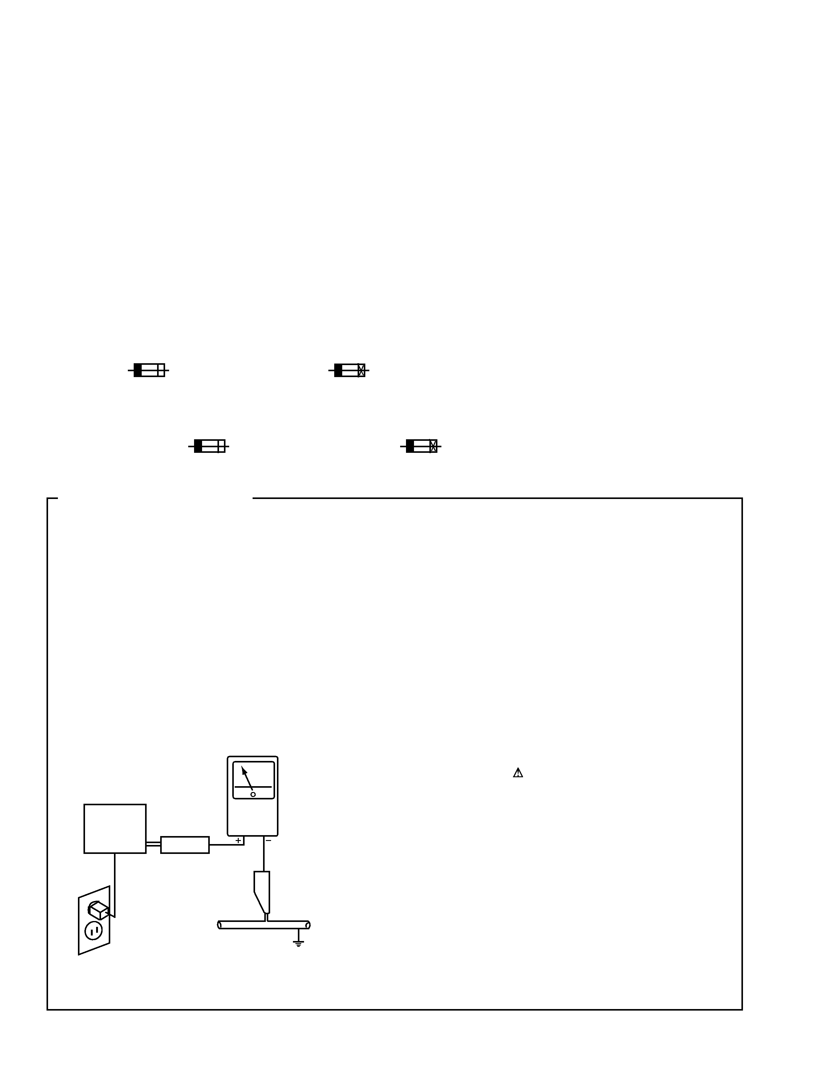
1. SAFETY PRECAUTIONS
The following check should be performed for the
continued protection of the customer and service
technician.
LEAKAGE CURRENT CHECK
Measure leakage current to a known earth ground (water
pipe, conduit, etc.) by connecting a leakage current tester
such as Simpson Model 229-2 or equivalent between the
earth ground and all exposed metal parts of the appliance
(input/output terminals, screwheads, metal overlays, control
shaft, etc.). Plug the AC line cord of the appliance directly
into a 120V AC 60Hz outlet and turn the AC power switch
on. Any current measured must not exceed 0.5mA.
(FOR USA MODEL ONLY)
Leakage
current
tester
Reading should
not be above
0.5mA
Device
under
test
Test all
exposed metal
surfaces
Also test with
plug reversed
(Using AC adapter
plug as required)
Earth
ground
AC Leakage Test
DV-444, DV-440
3
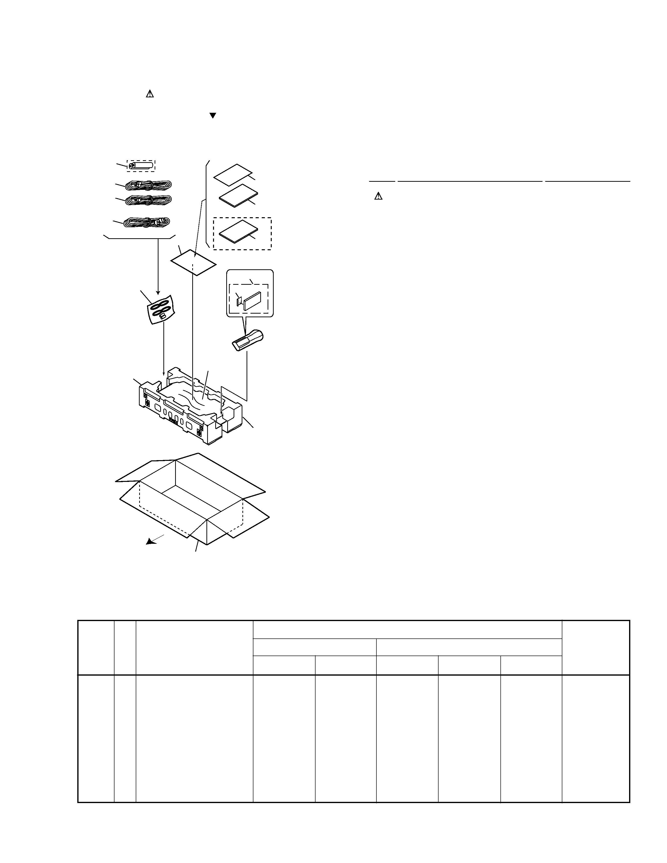
2.1 PACKING
1
Power Cord
ADG7022
2
Audio Cord (L = 1.5m)
See Contrast table (2)
3
Video Cord (L = 1.5m)
See Contrast table (2)
4
Remote Control Unit
See Contrast table (2)
5
Battery Cover
See Contrast table (2)
NSP
6
Dry Cell Battery (R6P, AA)
See Contrast table (2)
7
Pad
VHA1285
NSP
8
Warranty Card
ARY7045
9
Packing Case
See Contrast table (2)
10
Mirror Mat (0.5
× 750 × 600)
Z23-007
11
· · · · ·
12
Polyethylene Bag
VHL1051
(0.03
× 200 × 300)
13
Operating Instructions
See Contrast table (2)
14
Operating Instructions
See Contrast table (2)
(1) PACKING PARTS LIST
Mark No.
Description
Part No.
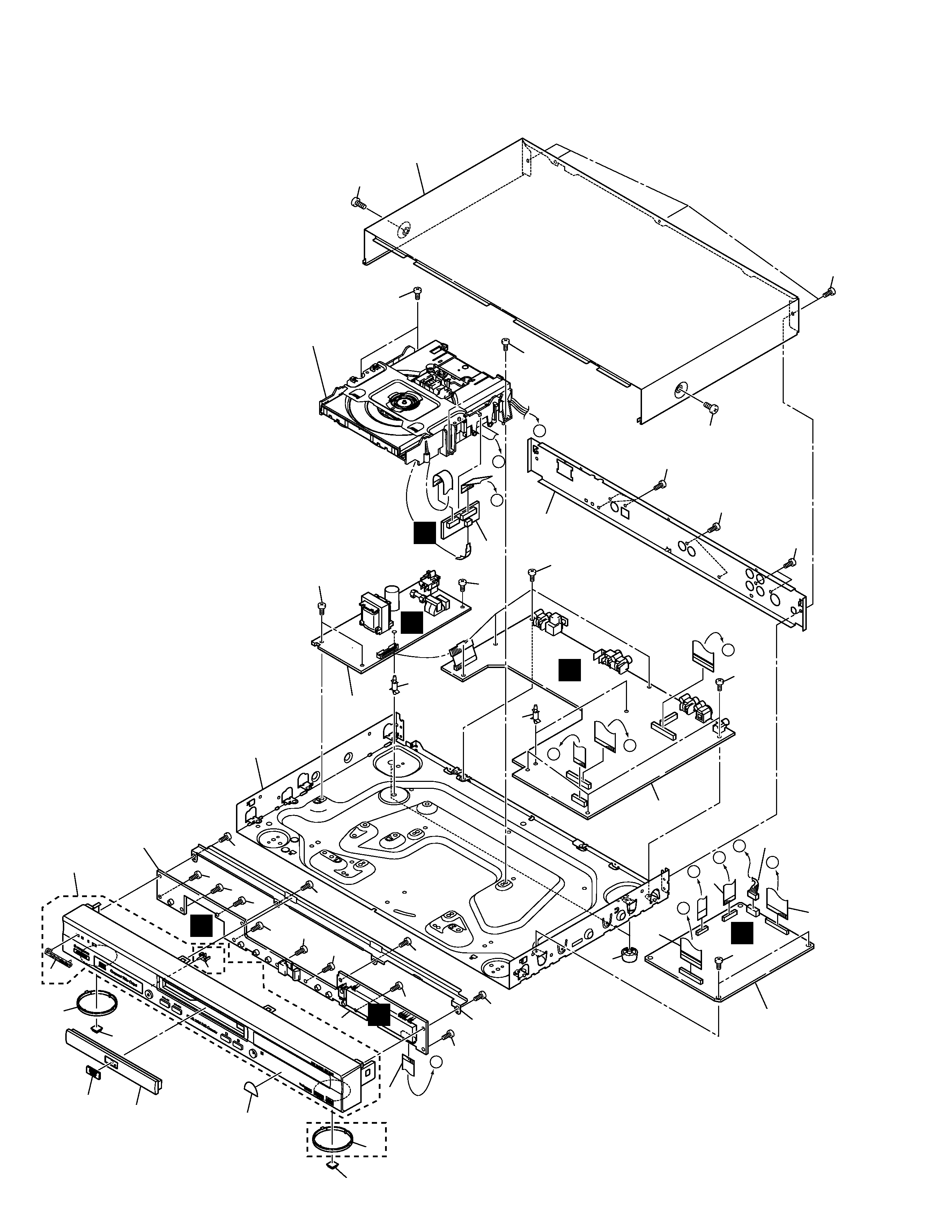
2. EXPLODED VIEWS AND PARTS LIST
NOTES:
· Parts marked by "NSP" are generally unavailable because they are not in our Master Spare Parts List.
· The mark found on some component parts indicates the importance of the safety factor of the part.
Therefore, when replacing, be sure to use parts of identical designation.
· Screws adjacent to mark on the product are used for disassembly.
FRONT
14
13
12
12
9
8
5
4
6
3
2
1
7 (1/2)
7 (2/2)
10
DV-444/KCXQ,
DV-440/KCXJ
Only
Mark
(2) CONTRAST TABLE
DV-444/KUXQ, KCXQ, DV-440/KUXQ, KUXJ and KCXJ are constructed the same except for the following:
2
Audio Cord (L = 1.5m)
VDE1054
VDE1054
VDE1054
VDE1052
VDE1052
3
Video Cord (L = 1.5m)
VDE1055
VDE1055
VDE1055
VDE1053
VDE1053
4
Remote Control Unit
VXX2703
VXX2703
VXX2702
VXX2702
VXX2702
5
Battery Cover
AZA7204
AZA7204
VNK4631
VNK4631
VNK4631
NSP
6
Dry Cell Battery (R6P, AA)
VEM1010
VEM1010
VEM1010
VEM-013
VEM-013
9
Packing Case
VHG2079
VHG2120
VHG2128
VHG2127
VHG2129
13
Operating Instructions
VRB1269
VRB1269
VRB1277
VRB1277
VRB1277
(English)
14
Operating Instructions
Not used
VRC1130
Not used
Not used
VRC1144
(French)
Remarks
Part No.
KUXQ
KCXQ
KUXQ
KUXJ
KCXJ
Symbol and Description
No.
DV-444
DV-440
DV-444, DV-440
4
A
A
B
D
E
F
B
C
C
D
F
E
20
23
31
21
21
24
24
26
25
30
30
30
30
30
30
30
30
30
30
22
5
9
6
30
30
27
27
14
15
27
27
27
16
28
28
2
28
29
12
11
11
8
4
10
1
17
7
3
28
28
28
29
18
B
D
H
C
F
G
Refer to
"2.3 LOADING MECHANISM ASSY".
DV-444
Only
32 DV-444
Only
2.2 EXTERIOR SECTION
DV-444, DV-440
5
1
DVDM Assy
See Contrast table (2)
NSP
2
Loading Mechanism Assy
VWT1188
NSP
3
SSIB Assy
VWG2292
4
JACB Assy
See Contrast table (2)
NSP
5
FLKB Assy
See Contrast table (2)
NSP
6
KEYB Assy
See Contrast table (2)
7
POWER SUPPLY Unit
VWR1339
8
Flexible Cable (16P)
See Contrast table (2)
9
Flexible Cable (17P)
See Contrast table (2)
10
Flexible Cable (30P)
See Contrast table (2)
11
Leg Assy SX
AEC7113
12
Connector Assy
PG05KK-E30
13
· · · · ·
NSP
14
PCB Support
REC1285
15
PCB Support
VEC2184
(1) EXTERIOR SECTION PARTS LIST
Mark No.
Description
Part No.
Mark No.
Description
Part No.
16
Rear Panel
See Contrast table (2)
NSP
17
Base Chassis
VNA2300
18
Bonnet
See Contrast table (2)
19
· · · · ·
20
DVD-V Plate
VAM1121
21
Rubber Foot
VEB1325
22
FP Angle
VNE2250
23
Tray Panel
See Contrast table (2)
24
Ring
See Contrast table (2)
25
Front Panel Assy
See Contrast table (2)
26
Pioneer Name Plate
See Contrast table (2)
27
Screw
BBZ30P060FMC
28
Screw
BBZ30P080FZK
29
Screw
See Contrast table (2)
30
Screw
BBZ30P100FZK
NSP
31
Energy Star Label
AAX7876
32
LED Lens
See Contrast table (2)
(2) CONTRAST TABLE
DV-444/KUXQ, KCXQ, DV-440/KUXQ, KUXJ and KCXJ are constructed the same except for the following:
Mark
1
DVDM Assy
VWS1485
VWS1487
VWS1487
4
JACB Assy
VWV1840
VWV1899
VWV1844
5
FLKB Assy
VWG2280
VWG2332
VWG2332
6
KEYB Assy
VWG2289
VWG2290
VWG2290
8
Flexible Cable (16P)
VDA1861
VDA1861
VDA1860
9
Flexible Cable (17P)
VDA1863
VDA1863
VDA1862
10
Flexible Cable (30P)
VDA1872
VDA1872
VDA1871
16
Rear Panel
VNA2303
VNA2379
VNA2378
18
Bonnet S
Not used
Not used
VXX2775
18
Bonnet
VNA2333
VNA2331
Not used
23
Tray Panel
VNK4837
VNK4835
VNK4835
24
Ring
VNK4840
Not used
Not used
25
Front Panel Assy
VXA2465
VXA2478
VXA2478
26
Pioneer Name Plate
VAM1129
VAM1109
VAM1109
29
Screw
BCZ40P060FNI
BCZ40P060FZK
BCZ40P060FZK
32
LED Lens
VNK4841
Not used
Not used
Remarks
Part No.
KUXQ
KCXQ
KUXQ
KUXJ
KCXJ
Symbol and Description
No.
DV-444
DV-440