ORDER NO.
PIONEER ELECTRONIC CORPORATION 4-1, Meguro 1-Chome, Meguro-ku, Tokyo 153-8654, Japan
PIONEER ELECTRONICS SERVICE, INC. P.O. Box 1760, Long Beach, CA 90801-1760, U.S.A.
PIONEER ELECTRONIC (EUROPE) N.V. Haven 1087, Keetberglaan 1, 9120 Melsele, Belgium
PIONEER ELECTRONICS ASIACENTRE PTE. LTD. 501 Orchard Road, #10-00 Wheelock Place, Singapore 238880
PIONEER ELECTRONIC CORPORATION 1998
c
DV-515
RRV2003
1. SAFETY INFORMATION ...................................... 2
2. EXPLODED VIEWS AND PARTS LIST ................ 3
3. SCHEMATIC DIAGRAM ..................................... 12
4. PCB CONNECTION DIAGRAM .......................... 29
5. PCB PARTS LIST ............................................... 39
6. ADJUSTMENT .................................................... 44
CONTENTS
7. GENERAL INFORMATION ................................ 46
7.1 PARTS ......................................................... 46
7.1.1 IC ........................................................... 46
7.2 DISASSEMBLY ........................................... 50
7.3 BLOCK DIAGRAM ....................................... 51
8. PANEL FACILITIES AND SPECIFICATIONS .... 52
T IZE SEPT. 1998 Printed in Japan
DV-414
THIS MANUAL IS APPLICABLE TO THE FOLLOWING MODEL(S) AND TYPE(S).
DVD PLAYER
Type
Model
Power Requirement
Region No.
Remarks
DV-515
DV-414
RL
AC110-127/220-240V
3
RAM
AC110-127/220-240V
6
KU
AC120V
1
KC
AC120V
1
· Refer to the service guide RRV2004 for DV-515.
STANDBY
POWER
OFF
10 KEY OPERATION
TITLE
+10
VIRTUAL DOLBY
SURROND
FL OFF
1
6
2
7
3
8
4
9
5
0
0
7
1
4¡ ¢
£¥8
ON
· DV-515
2
DV-515, DV-414
1. SAFETY INFORMATION
This service manual is intended for qualified service technicians ; it is not meant for the casual do-it-
yourselfer. Qualified technicians have the necessary test equipment and tools, and have been trained
to properly and safely repair complex products such as those covered by this manual.
Improperly performed repairs can adversely affect the safety and reliability of the product and may
void the warranty. If you are not qualified to perform the repair of this product properly and safely, you
should not risk trying to do so and refer the repair to a qualified service technician.
WARNING
This product contains lead in solder and certain electrical parts contain chemicals which are known to the state of California to cause
cancer, birth defects or other reproductive harm.
Health & Safety Code Section 25249.6 Proposition 65
NOTICE
(FOR CANADIAN MODEL ONLY)
Fuse symbols
(fast operating fuse) and/or
(slow operating fuse) on PCB indicate that replacement parts must
be of identical designation.
REMARQUE
(POUR MODÈLE CANADIEN SEULEMENT)
Les symboles de fusible
(fusible de type rapide) et/ou
(fusible de type lent) sur CCI indiquent que les pièces
de remplacement doivent avoir la même désignation.
ANY MEASUREMENTS NOT WITHIN THE LIMITS
OUTLINED ABOVE ARE INDICATIVE OF A POTENTIAL
SHOCK HAZARD AND MUST BE CORRECTED BEFORE
RETURNING THE APPLIANCE TO THE CUSTOMER.
2. PRODUCT SAFETY NOTICE
Many electrical and mechanical parts in the appliance
have special safety related characteristics. These are
often not evident from visual inspection nor the protection
afforded by them necessarily can be obtained by using
replacement components rated for voltage, wattage, etc.
Replacement parts which have these special safety
characteristics are identified in this Service Manual.
Electrical components having such features are identified
by marking with a
on the schematics and on the parts list
in this Service Manual.
The use of a substitute replacement component which does
not have the same safety characteristics as the PIONEER
recommended replacement one, shown in the parts list in
this Service Manual, may create shock, fire, or other hazards.
Product Safety is continuously under review and new
instructions are issued from time to time. For the latest
information, always consult the current PIONEER Service
Manual. A subscription to, or additional copies of, PIONEER
Service Manual may be obtained at a nominal charge from
PIONEER.
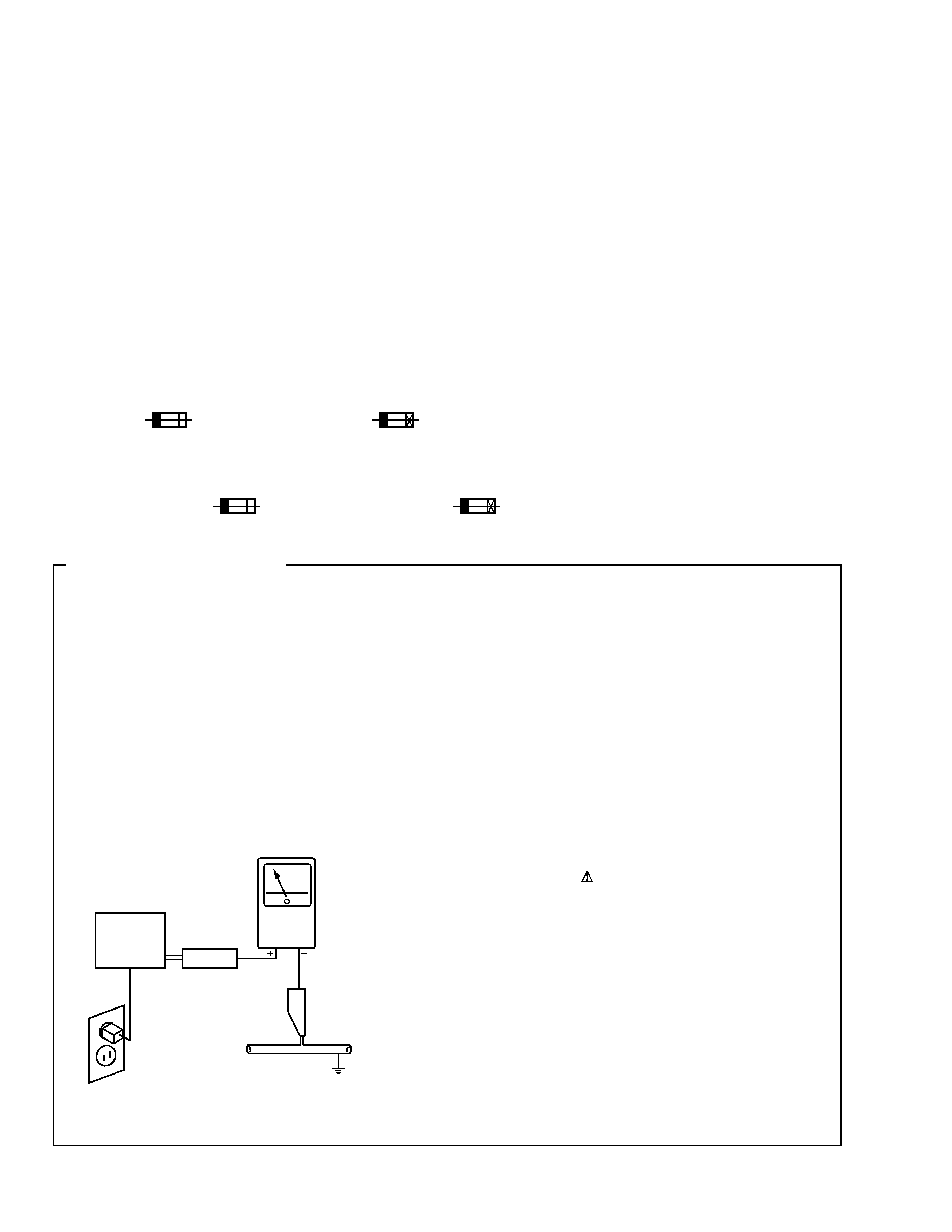
1. SAFETY PRECAUTIONS
The following check should be performed for the
continued protection of the customer and service
technician.
LEAKAGE CURRENT CHECK
Measure leakage current to a known earth ground (water
pipe, conduit, etc.) by connecting a leakage current tester
such as Simpson Model 229-2 or equivalent between the
earth ground and all exposed metal parts of the appliance
(input/output terminals, screwheads, metal overlays, control
shaft, etc.). Plug the AC line cord of the appliance directly
into a 120V AC 60Hz outlet and turn the AC power switch
on. Any current measured must not exceed 0.5mA.
(FOR USA MODEL ONLY)
Leakage
current
tester
Reading should
not be above
0.5mA
Device
under
test
Test all
exposed metal
surfaces
Also test with
plug reversed
(Using AC adapter
plug as required)
Earth
ground
AC Leakage Test
DV-515, DV-414
3
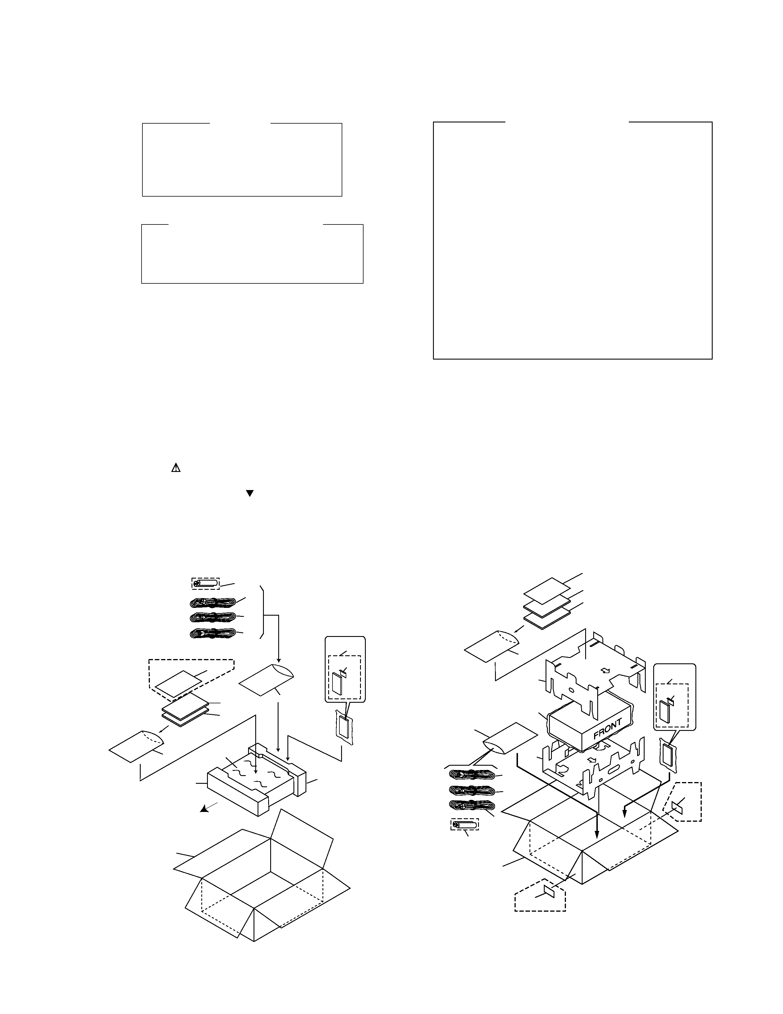
2.1 PACKING
2. EXPLODED VIEWS AND PARTS LIST
NOTES:
· Parts marked by "NSP" are generally unavailable because they are not in our Master Spare Parts List.
· The mark found on some component parts indicates the importance of the safety factor of the part.
Therefore, when replacing, be sure to use parts of identical designation.
· Screws adjacent to mark on the product are used for disassembly.
IMPORTANT
THIS PIONNER APPARATUS CONTAINS
LASER OF CLASS 1.
SERVICING OPERATION OF THE APPARATUS
SHOULD BE DONE BY A SPECIALLY
INSTRUCTED PERSON.
LASER DIODE CHARACTERISTICS
FOR DVD : MAXIMUM OUTPUT POWER : 7 mw
WAVELENGTH : 650 nm
FOR CD :
MAXIMUM OUTPUT POWER : 5mW
WAVELENGTH : 780 785 nm
Additional Laser Caution
1. Inside detection switch (S201 on the SMEB assy) and loading-
status detection switch (S301 on the LOSB assy) are detected
by the microprocessor (IC501 in the DVDM assy).
· To permit the laser diode to oscillate, it is required to set the
inside detection switch for the inside position (S201 : ON) and to
set the loading-status detection switch for the clamp position (the
center terminal of S301 is shorted to +5V). The 650 nm laser
diode for DVD oscillation will continue if pin 19 of IC101 is shorted
to +5V (fault condition) in the DVDM assy.
The 780 nm laser diode for CD oscillates if pin 20 of IC101 is
shorted to +5V in the DVDM assy.
In the test mode
, the laser diode oscillates when microproces-
sor detects a PLAY signal, or when the PLAY key is pressed
(S113 ON in the FLKB assy), with the above requirements satis-
fied.
2. When the cover is open, close viewing through the objective lens
with the naked eye will cause exposure to the laser beam.
: Refer to the service guide RRV2004.
10
8
3
4
4
(DV-515/RAM only)
11
14
DV-414
/KC only
DV-414
/KC only
10
12
16
15
1
6
5
13
7
19
19
10
8
3
10
16
15
5
13
7
6
1
17
18
14
FRONT
· For DV-515
· For DV-414
DV-515, DV-414
4
Mark No.
Description
Part No.
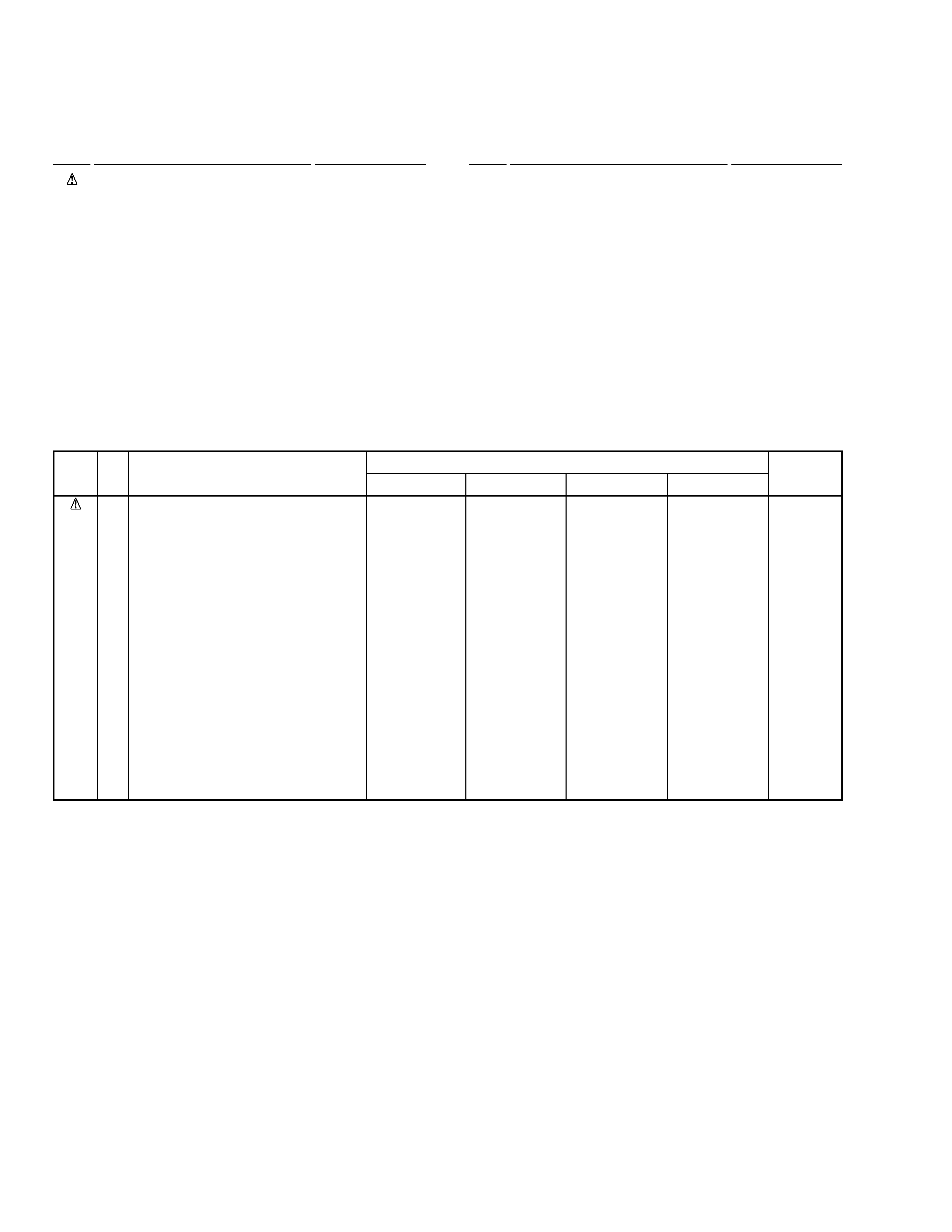
(1) PACKING PARTS LIST
1
AC Power Cord
See Contrast table (2)
2
· · · · ·
3
Operating Instructions
See Contrast table (2)
NSP
4
Warranty Card
See Contrast table (2)
5
Audio Cord
VDE1033
6
Video Cord
VDE1048
NSP
7
Dry Cell Battery (R6P,AA)
VEM-013
8
Operating Instructions
See Contrast table (2)
9
· · · · ·
10
Polyethylene Bag
Z21-038
(2) CONTRAST TABLE
DV-515/RL, RAM, DV-414/KU and KC are constructed the same except for the following :
k
r
a
M.
o
Nn
o
i
t
p
i
r
c
s
e
D
d
n
a
l
o
b
m
y
S
.
o
N
t
r
a
P
s
k
r
a
m
e
R
L
R
/
5
1
5
-
V
DM
A
R
/
5
1
5
-
V
DU
K
/
4
1
4
-
V
DC
K
/
4
1
4
-
V
D
P
S
N
1
3
3
3
4
8
8
1
1
2
1
3
1
5
1
5
1
7
1
8
1
9
1
d
r
o
C
r
e
w
o
P
C
A
s
n
o
i
t
c
u
r
t
s
n
I
g
n
i
t
a
r
e
p
O
)
e
g
a
u
g
n
a
L
e
s
e
n
i
h
C
.
d
a
r
T
(
s
n
o
i
t
c
u
r
t
s
n
I
g
n
i
t
a
r
e
p
O
)
e
g
a
u
g
n
a
L
e
s
e
n
i
h
C
.
p
m
i
S
(
)
h
c
n
e
r
F
(
s
n
o
i
t
c
u
r
t
s
n
I
g
n
i
t
a
r
e
p
O
d
r
a
C
y
t
n
a
r
r
a
W
)
h
s
il
g
n
E
(
s
n
o
i
t
c
u
r
t
s
n
I
g
n
i
t
a
r
e
p
O
)
h
s
il
g
n
E
(
s
n
o
i
t
c
u
r
t
s
n
I
g
n
i
t
a
r
e
p
O
A
r
o
t
c
e
t
o
r
P
B
r
o
t
c
e
t
o
r
P
e
s
a
C
g
n
i
k
c
a
P
)
8
2
0
V
D
-
U
C
(
t
i
n
U
l
o
r
t
n
o
C
e
t
o
m
e
R
)
2
2
0
V
D
-
U
C
(
t
i
n
U
l
o
r
t
n
o
C
e
t
o
m
e
R
F
d
a
P
R
d
a
P
l
e
b
a
L
C
K
7
2
1
1
G
D
A
8
7
0
1
C
R
V
d
e
s
u
t
o
N
d
e
s
u
t
o
N
d
e
s
u
t
o
N
4
0
2
1
B
R
V
d
e
s
u
t
o
N
d
e
s
u
t
o
N
d
e
s
u
t
o
N
3
7
7
1
G
H
V
0
0
6
2
X
X
V
d
e
s
u
t
o
N
0
2
2
1
A
H
V
1
2
2
1
A
H
V
d
e
s
u
t
o
N
7
1
0
7
G
D
A
d
e
s
u
t
o
N
9
7
0
1
C
R
V
d
e
s
u
t
o
N
8
2
0
7
Y
R
A
4
0
2
1
B
R
V
d
e
s
u
t
o
N
d
e
s
u
t
o
N
d
e
s
u
t
o
N
4
7
7
1
G
H
V
0
0
6
2
X
X
V
d
e
s
u
t
o
N
0
2
2
1
A
H
V
1
2
2
1
A
H
V
d
e
s
u
t
o
N
1
2
0
7
G
D
A
d
e
s
u
t
o
N
d
e
s
u
t
o
N
d
e
s
u
t
o
N
3
2
0
7
Y
R
A
d
e
s
u
t
o
N
9
9
1
1
B
R
V
0
6
0
1
B
H
V
1
6
0
1
B
H
V
6
5
7
1
G
H
V
d
e
s
u
t
o
N
9
9
5
2
X
X
V
d
e
s
u
t
o
N
d
e
s
u
t
o
N
d
e
s
u
t
o
N
1
2
0
7
G
D
A
d
e
s
u
t
o
N
d
e
s
u
t
o
N
7
7
0
1
C
R
V
4
2
0
7
Y
R
A
d
e
s
u
t
o
N
9
9
1
1
B
R
V
0
6
0
1
B
H
V
1
6
0
1
B
H
V
6
5
7
1
G
H
V
d
e
s
u
t
o
N
9
9
5
2
X
X
V
d
e
s
u
t
o
N
d
e
s
u
t
o
N
6
1
7
1
W
R
V
Mark No.
Description
Part No.
11
Protector A
See Contrast table (2)
12
Protector B
See Contrast table (2)
13
Packing Case
See Contrast table (2)
14
Mirror Mat Sheet 750x600x0.5 Z23-007
15
Remote Control Unit
See Contrast table (2)
16
Battery Cover
AZA7204
17
Pad F
See Contrast table (2)
18
Pad R
See Contrast table (2)
19
KC Label
See Contrast table (2)
DV-515, DV-414
5
3
2
4
10
5
11
Refer to "2.3 FRONT PANEL SECTION"
10
8
9
DV-515/RL only
DV-414/KU only
7
6
11
14
13
12
15
17
16
1
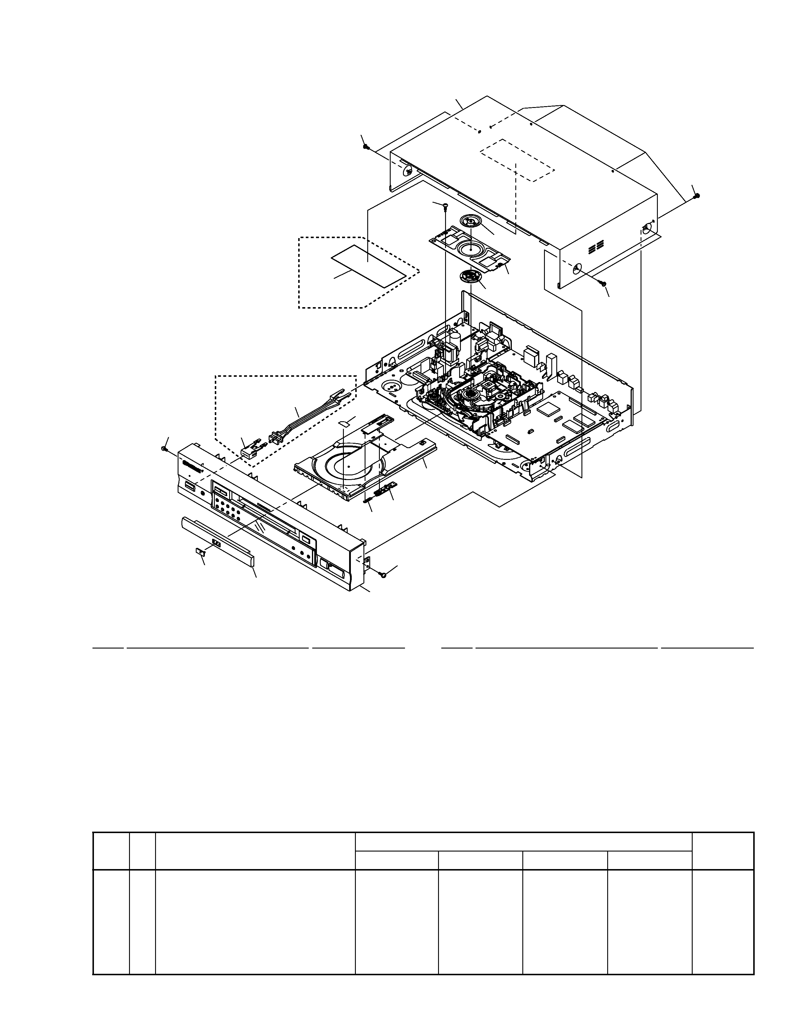
2.2 EXTERIOR SECTION
Mark No.
Description
Part No.
Mark No.
Description
Part No.
(1) EXTERIOR SECTION PARTS LIST
1
Bonnet Case S
See Contrast table (2)
2
Tray Panel
See Contrast table (2)
3
DVD Plate
VAM1075
4
POWER Button
See Contrast table (2)
5
PW Button Joint
See Contrast table (2)
6Tray
See Contrast table (2)
7
Tray Stopper
VNL1739
8
Spring
VBH1277
9
Tray Label
VRW1628
10
Screw
IBZ30P080FMC
11
Screw
See Contrast table (2)
12
Clamper Plate
VNE2068
13
Bridge
VNE2069
14
Clamper
VNL1738
15
Screw
BPZ26P080FZK
16
Screw
BBZ30P080FMC
17
65 Label
See Contrast table (2)
(2) CONTRAST TABLE
DV-515/RL, RAM, DV-414/KU and KC are constructed the same except for the following :
k
r
a
M.
o
Nn
o
i
t
p
i
r
c
s
e
D
d
n
a
l
o
b
m
y
S
.
o
N
t
r
a
P
s
k
r
a
m
e
R
L
R
/
5
1
5
-
V
DM
A
R
/
5
1
5
-
V
DU
K
/
4
1
4
-
V
DC
K
/
4
1
4
-
V
D
1
2
4
5
6
1
1
7
1
S
e
s
a
C
t
e
n
n
o
B
l
e
n
a
P
y
a
r
T
n
o
t
t
u
B
R
E
W
O
P
t
n
i
o
J
n
o
t
t
u
B
W
P
y
a
r
T
w
e
r
c
S
l
e
b
a
L
5
6
5
1
6
2
X
X
V
0
1
3
4
K
N
V
9
5
1
4
K
N
V
9
7
1
4
K
N
V
3
3
3
4
K
N
V
I
N
F
0
6
0
P
0
4
Z
C
B
d
e
s
u
t
o
N
5
1
6
2
X
X
V
0
1
3
4
K
N
V
d
e
s
u
t
o
N
d
e
s
u
t
o
N
3
3
3
4
K
N
V
I
N
F
0
6
0
P
0
4
Z
C
B
d
e
s
u
t
o
N
2
1
6
2
X
X
V
6
1
3
4
K
N
V
d
e
s
u
t
o
N
d
e
s
u
t
o
N
1
3
7
1
L
N
V
K
Z
F
0
6
0
P
0
4
Z
C
B
9
6
0
1
W
R
O
2
1
6
2
X
X
V
6
1
3
4
K
N
V
d
e
s
u
t
o
N
d
e
s
u
t
o
N
1
3
7
1
L
N
V
K
Z
F
0
6
0
P
0
4
Z
C
B
d
e
s
u
t
o
N