ORDER NO.
PIONEER CORPORATION 4-1, Meguro 1-chome, Meguro-ku, Tokyo 153-8654, Japan
PIONEER ELECTRONICS (USA) INC. P.O. Box 1760, Long Beach, CA 90801-1760, U.S.A.
PIONEER EUROPE NV Haven 1087, Keetberglaan 1, 9120 Melsele, Belgium
PIONEER ELECTRONICS ASIACENTRE PTE. LTD. 253 Alexandra Road, #04-01, Singapore 159936
PIONEER CORPORATION 2004
DV-270-S
RRV2874
DVD PLAYER
DV-270-S
DV-275-S
THIS MANUAL IS APPLICABLE TO THE FOLLOWING MODEL(S) AND TYPE(S).
Model
Type
Power Requirement
Region No.
Serial No.
Confirm 3rd & 4th
alphabetical letters.
DV-270-S
KUXCN/CA
AC120V
1
&&TE######$$
DV-275-S
KUXCN
AC120V
1
&&TE######$$
DV-275-S
KCXCN
AC120V
1
&&TE######$$
For details, refer to "Important symbols for good services".
T-ZZE FEB. 2004 printed in Japan
DV-270-S
2
1234
123
4
C
D
F
A
B
E
SAFETY INFORMATION
This service manual is intended for qualified service technicians; it is not meant for the casual
do-it-yourselfer. Qualified technicians have the necessary test equipment and tools, and have been
trained to properly and safely repair complex products such as those covered by this manual.
Improperly performed repairs can adversely affect the safety and reliability of the product and may
void the warranty. If you are not qualified to perform the repair of this product properly and safely, you
should not risk trying to do so and refer the repair to a qualified service technician.
WARNING
This product contains lead in solder and cer tain electrical par ts contain chemicals which are known to the state of California to
cause cancer, bir th defects or other reproductive harm.
Health & Safety Code Section 25249.6 Proposition 65
NOTICE
(FOR CANADIAN MODEL ONLY)
Fuse symbols
(fast operating fuse)
and/or
(slow operating fuse) on PCB indicate that replacement
parts must be of identical designation.
REMARQUE
(POUR MODÈLE CANADIEN SEULEMENT)
Les symboles de fusible
(fusible de type rapide)
et/ou
(fusible de type lent) sur CCI indiquent que
les pièces de remplacement doivent avoir la même désignation.
ANY MEASUREMENTS NOT WITHIN THE
LIMITS OUTLINED ABOVE ARE INDICATIVE
OF A POTENTIAL SHOCK HAZARD AND
MUST BE CORRECTED BEFORE RETURN-
ING THE APPLIANCE TO THE CUSTOMER.
2. PRODUCT SAFETY NOTICE
Many electrical and mechanical parts in the appliance
have special safety related character istics. These are
often not evident
from visual
inspection nor the
protection afforded by them necessarily can be obtained
by using replacement components rated for voltage,
wattage, etc. Replacement par ts which have these
special safety character istics are identified in this
Service Manual.
Electr ical components having such features are
identified by marking with a
on the schematics and
on the parts list in this Service Manual.
The use of a substitute replacement component which
does not have the same safety characteristics as the
PIONEER recommended replacement one, shown in the
parts list in this Service Manual, may create shock, fire,
or other hazards.
Product Safety is continuously under review and new
instructions are issued from time to time. For the latest
infor mation, always consult the current PIONEER
Service Manual. A subscription to, or
additional copies
of, PIONEER Ser vice Manual may be obtained at a
nominal charge from PIONEER.
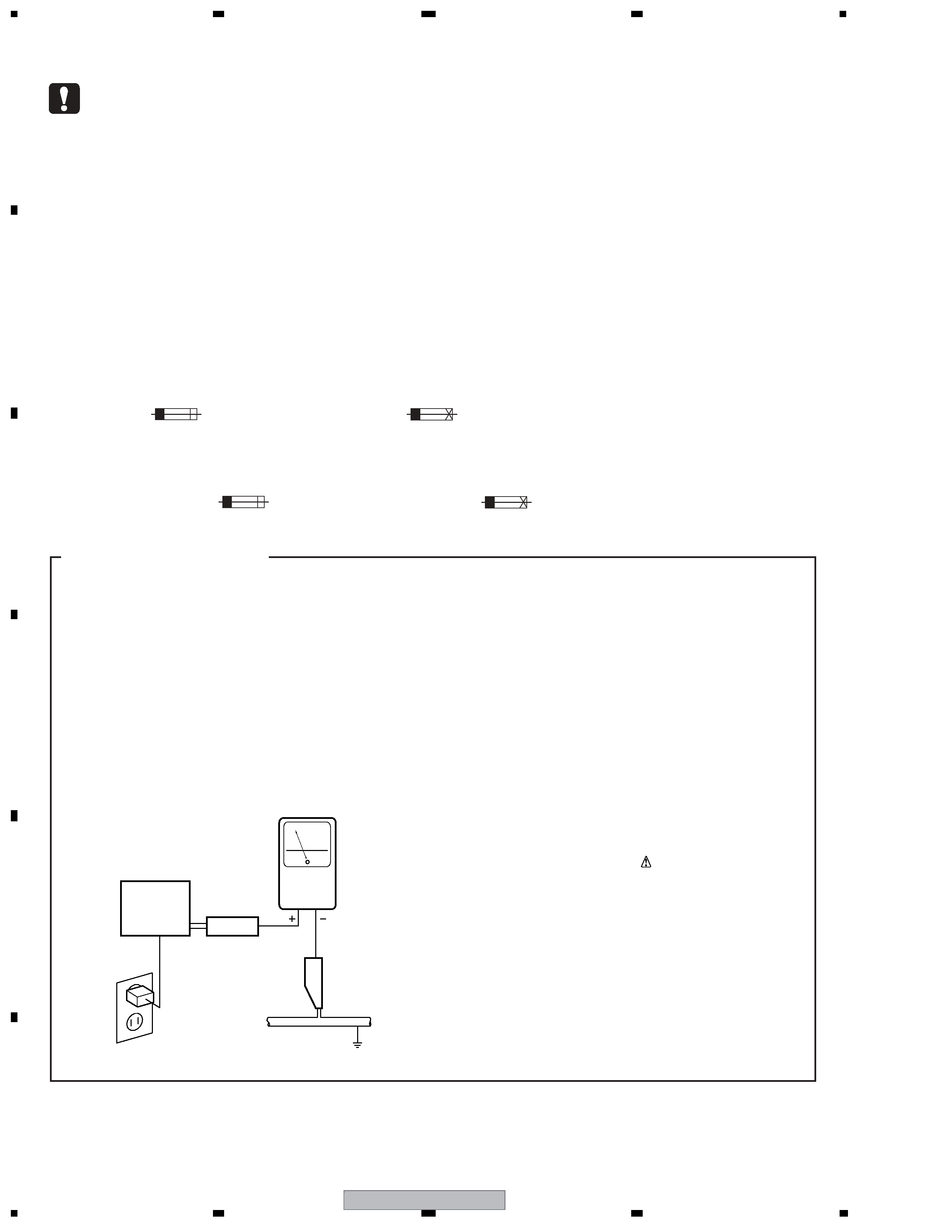
(FOR USA MODEL ONLY)
1. SAFETY PRECAUTIONS
The following check should be perfor med for the
continued protection of the customer and ser vice
technician.
LEAKAGE CURRENT CHECK
Measure leakage current to a known ear th ground
(water pipe, conduit, etc.) by connecting a leakage
current tester such as Simpson Model 229-2 or
equivalent between the ear th ground and all exposed
metal par ts of the appliance (input/output ter minals,
screwheads, metal overlays, control shaft, etc.). Plug
the AC line cord of the appliance directly into a 120V
AC 60 Hz outlet and turn the AC power switch on. Any
current measured must not exceed 0.5 mA.
Device
under
test
Leakage
current
tester
Earth
ground
Reading should
not be above
0.5 mA
Also test with
plug reversed
(Using AC adapter
plug as required)
Test all
exposed metal
surfaces
AC Leakage Test
DV-270-S
3
5
678
56
7
8
C
D
F
A
B
E
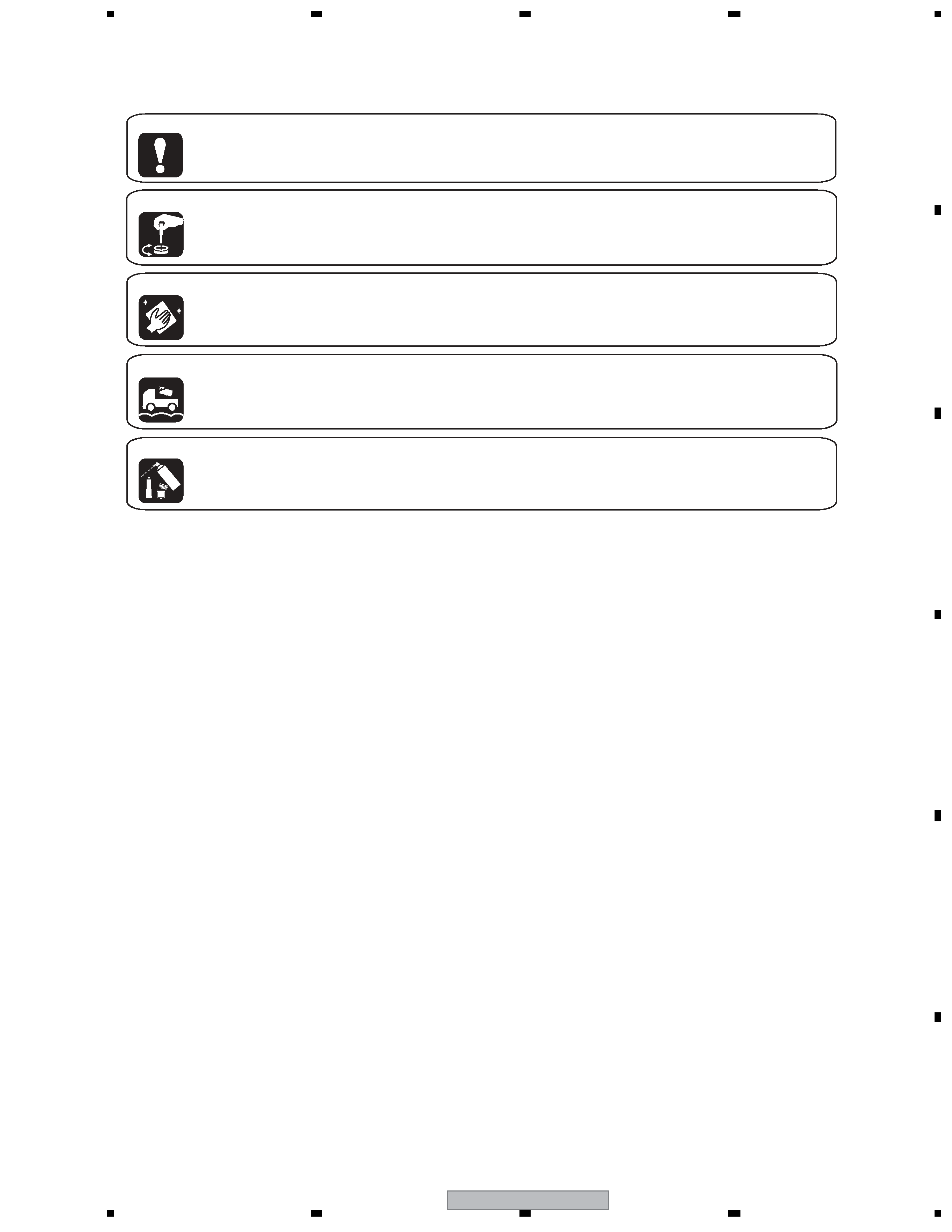
[ Important symbols for good services ]
In this manual, the symbols shown-below indicate that adjustments, settings or cleaning should be made securely.
When you find the procedures bearing any of the symbols, be sure to fulfill them:
2. Adjustments
To keep the original performances of the product, optimum adjustments or specification confirmation is indispensable.
In accordance with the procedures or instructions described in this manual, adjustments should be performed.
3. Cleaning
For optical pickups, tape-deck heads, lenses and mirrors used in projection monitors, and other parts requiring cleaning,
proper cleaning should be performed to restore their performances.
5. Lubricants, glues, and replacement parts
Appropriately applying grease or glue can maintain the product performances. But improper lubrication or applying
glue may lead to failures or troubles in the product. By following the instructions in this manual, be sure to apply the
prescribed grease or glue to proper portions by the appropriate amount.For replacement parts or tools, the prescribed
ones should be used.
4. Shipping mode and shipping screws
To protect the product from damages or failures that may be caused during transit, the shipping mode should be set or
the shipping screws should be installed before shipping out in accordance with this manual, if necessary.
1. Product safety
You should conform to the regulations governing the product (safety, radio and noise, and other regulations), and
should keep the safety during servicing by following the safety instructions described in this manual.

DV-270-S
4
1234
123
4
C
D
F
A
B
E
CONTENTS
SAFETY INFORMATION ..................................................................................................................................... 2
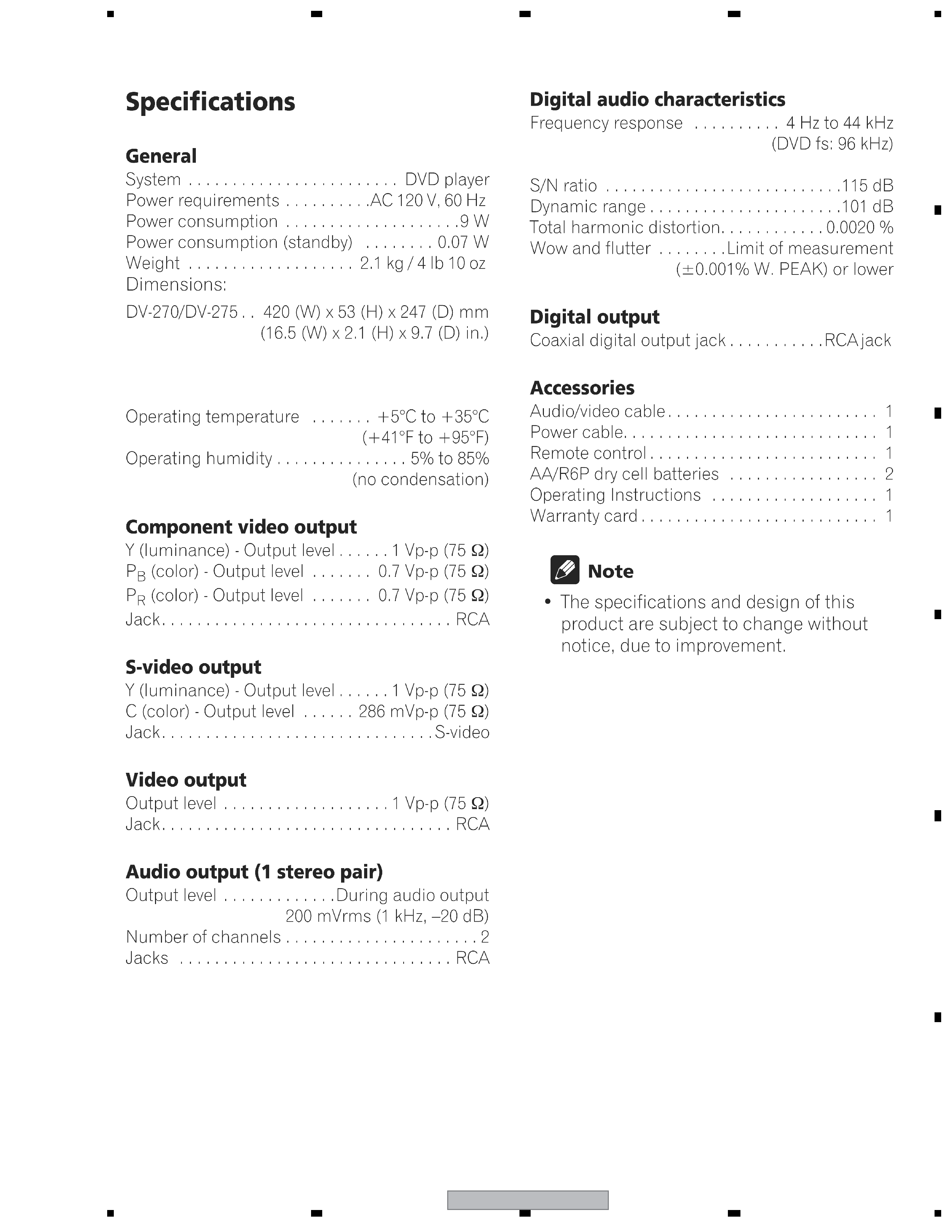
1. SPECIFICATIONS ............................................................................................................................................ 5
2. EXPLODED VIEWS AND PARTS LIST ............................................................................................................ 6
2.1 PACKING ................................................................................................................................................... 6
2.2 EXTERIOR SECTION................................................................................................................................ 8
2.3 FRONT PANEL SECTION ....................................................................................................................... 10
2.4 04 LOADER ASSY................................................................................................................................... 12
3. BLOCK DIAGRAM AND SCHEMATIC DIAGRAM ..........................................................................................14
3.1 OVERALL BLOCK DIAGRAM.................................................................................................................. 14
3.2 POWER SUPPLY BLOCK DIAGRAM ...................................................................................................... 16
3.3 WAVEFORMS .......................................................................................................................................... 18
3.4 LOAB ASSY and OVERALL WIRING DIAGRAM..................................................................................... 20
3.5 DVDM ASSY 1/4 [RF IC BLOCK]............................................................................................................. 22
3.6 DVDM ASSY 2/4 [DVD IC BLOCK] .......................................................................................................... 24
3.7 DVDM ASSY 3/4 [AUDIO BLOCK]........................................................................................................... 26
3.8 DVDM ASSY 4/4 [VIDEO BLOCK]........................................................................................................... 28
3.9 FLKY and IRKY ASSYS........................................................................................................................... 30
3.10 POWER SUPPLY UNIT [VWR1376] ...................................................................................................... 32
4. PCB CONNECTION DIAGRAM ..................................................................................................................... 33
4.1 LOAB ASSY ............................................................................................................................................. 33
4.2 DVDM ASSY ............................................................................................................................................ 34
4.3 FLKY and IRKY ASSYS........................................................................................................................... 38
4.4 POWER SUPPLY UNIT [VWR1376] ........................................................................................................ 40
5. PCB PARTS LIST ........................................................................................................................................... 42
6. ADJUSTMENT ............................................................................................................................................... 44
6.1 ADJUSTMENT ITEMS AND LOCATION ................................................................................................. 44
6.2 JIGS AND MEASURING INSTRUMENTS ............................................................................................... 44
6.3 NECESSARY ADJUSTMENT POINTS ................................................................................................... 45
6.4 TEST MODE ............................................................................................................................................ 46
6.5 MECHANISM ADJUSTMENT .................................................................................................................. 47
7. GENERAL INFORMATION ............................................................................................................................. 49
7.1 DIAGNOSIS ............................................................................................................................................. 49
7.1.1 TEST MODE ......................................................................................................................................... 49
7.1.2 DISPLAY SPECIFICATION OF THE TEST MODE ............................................................................... 50
7.1.3 FUNCTIONAL SPECIFICATION OF THE SHORTCUT KEY ................................................................ 51
7.1.4 SPECIFICATION OF MODEL INFORMATION DISPLAY...................................................................... 52
7.1.5 FUNCTIONAL SPECIFICATION OF THE SERVICE MODE................................................................. 53
7.1.6 METHOD FOR DIAGNOSING DEGRADATION OF THE LDS ON THE PICKUP ASSY...................... 54
7.1.7 TROUBLE SHOOTING ......................................................................................................................... 55
7.1.8 ID NUMBER AND ID DATA SETTING................................................................................................... 58
7.1.9 SEQUENCE AFTER POWER ON ........................................................................................................ 61
7.1.10 DISASSEMBLY ................................................................................................................................... 62
7.2 IC ............................................................................................................................................................. 70
7.3 DISC / CONTENT FORMAT PLAYBACK COMPATIBILITY ..................................................................... 86
7.4 CLEANING............................................................................................................................................... 88
8. PANEL FACILITIES ........................................................................................................................................ 89
DV-270-S
5
5
678
56
7
8
C
D
F
A
B
E
1. SPECIFICATIONS