ORDER NO.
PIONEER CORPORATION 4-1, Meguro 1-chome, Meguro-ku, Tokyo 153-8654, Japan
PIONEER ELECTRONICS (USA) INC. P.O. Box 1760, Long Beach, CA 90801-1760, U.S.A.
PIONEER EUROPE NV Haven 1087, Keetberglaan 1, 9120 Melsele, Belgium
PIONEER ELECTRONICS ASIACENTRE PTE. LTD. 253 Alexandra Road, #04-01, Singapore 159936
PIONEER CORPORATION 2003
DRM-3000
RRV2734
300 DISC CHANGER
DRM-3000
THIS MANUAL IS APPLICABLE TO THE FOLLOWING MODEL(S) AND TYPE(S).
Model
Type
Power Requirement
Remarks
DRM-3000
TUCYV/WL
AC100 - 240V
For details, refer to "Important symbols for good services" .
T-ZZY MAR. 2003 printed in Japan
DRM-3000
2
1234
123
4
C
D
F
A
B
E
SAFETY INFORMATION
This service manual is intended for qualified service technicians ; it is not meant for the casual
do-it-yourselfer. Qualified technicians have the necessary test equipment and tools, and have been
trained to properly and safely repair complex products such as those covered by this manual.
Improperly performed repairs can adversely affect the safety and reliability of the product and may
void the warranty. If you are not qualified to perform the repair of this product properly and safely,
you should not risk trying to do so and refer the repair to a qualified service technician.
WARNING
This product contains lead in solder and certain electrical parts contain chemicals which are known to the state of California to
cause cancer, birth defects or other reproductive harm.
Health & Safety Code Section 25249.6 - Proposition 65
NOTICE
(FOR CANADIAN MODEL ONLY)
Fuse symbols
(fast operating fuse) and/or
(slow operating fuse) on PCB indicate that replacement parts
must be of identical designation.
REMARQUE
(POUR MODÈLE CANADIEN SEULEMENT)
Les symboles de fusible
(fusible de type rapide) et/ou
(fusible de type lent) sur CCI indiquent que les pièces
de remplacement doivent avoir la même désignation.
1. SAFETY PRECAUTIONS
The following check should be performed for the
continued protection of the customer and service
technician.
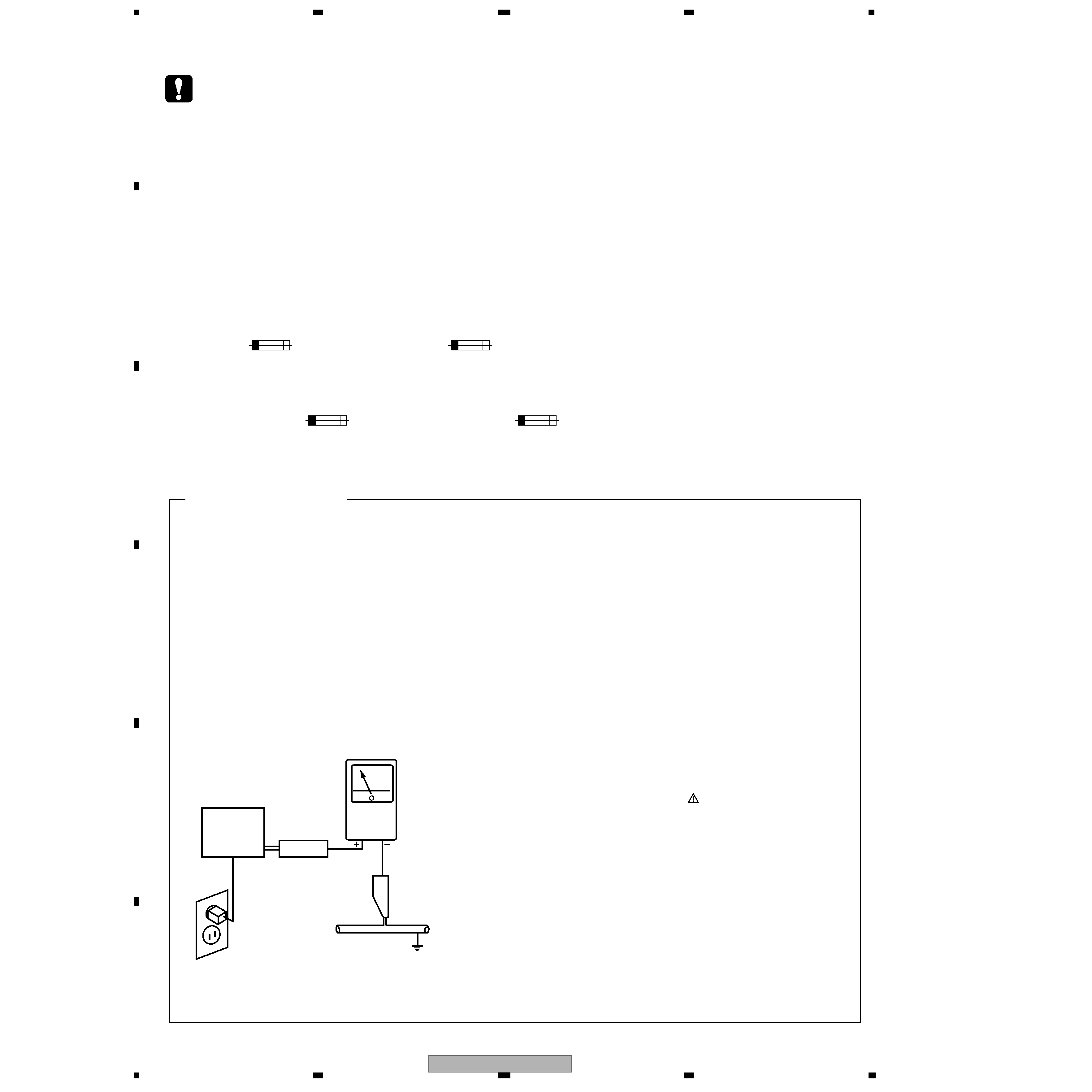
LEAKAGE CURRENT CHECK
Measure leakage current to a known earth ground
(water pipe, conduit, etc.) by connecting a leakage
current tester such as Simpson Model 229-2 or
equivalent between the earth ground and all exposed
metal parts of the appliance (input/output terminals,
screwheads, metal overlays, control shaft, etc.). Plug
the AC line cord of the appliance directly into a 120V
AC 60Hz outlet and turn the AC power switch on. Any
current measured must not exceed 0.5mA.
ANY MEASUREMENTS NOT WITHIN THE LIMITS
OUTLINED
ABOVE
ARE
INDICATIVE
OF
A
POTENTIAL
SHOCK
HAZARD
AND
MUST
BE
CORRECTED
BEFORE
RETURNING
THE
APPLIANCE TO THE CUSTOMER.
2. PRODUCT SAFETY NOTICE
Many electrical and mechanical parts in the appliance
have special safety related characteristics. These are
often not evident from visual inspection nor the
protection afforded by them necessarily can be obtained
by using replacement components rated for voltage,
wattage, etc. Replacement parts which have these
special safety characteristics are identified in this
Service Manual.
Electrical components having such features are
identified by marking with a
on the schematics and on
the parts list in this Service Manual.
The use of a substitute replacement component which
does not have the same safety characteristics as the
PIONEER recommended replacement one, shown in the
parts list in this Service Manual, may create shock, fire,
or other hazards.
Product Safety is continuously under review and new
instructions are issued from time to time. For the latest
information, always consult the current PIONEER
Service Manual. A subscription to, or additional copies
of, PIONEER Service Manual may be obtained at a
nominal charge from PIONEER.
Leakage
current
tester
Reading should
not be above
3.5 mA
Device
under
test
Test all
exposed metal
surfaces
Also test with
plug reversed
(Using AC adapter
plug as required)
Earth
ground
AC Leakage Test
(FOR USA MODEL ONLY)
DRM-3000
3
5
678
56
7
8
C
D
F
A
B
E
CONTENTS
SAFETY INFORMATION......................................................................................................................................2
1. SPECIFICATIONS .............................................................................................................................................5
2. EXPLODED VIEWS AND PARTS LIST.............................................................................................................6
2.1 PACKING ....................................................................................................................................................6
2.2 REAR DOOR SECTION .............................................................................................................................8
2.3 FRONT SECTION (1) .................................................................................................................................9
2.4 FRONT SECTION (2) ...............................................................................................................................10
2.5 UNDER SIDE SECTION...........................................................................................................................12
2.6 MAIL SLOT SECTION ..............................................................................................................................14
2.7 UP SIDE AND FLAME SECTION.............................................................................................................16
2.8 RIGHT SIDE SECTION (1).......................................................................................................................18
2.9 RIGHT SIDE SECTION (2).......................................................................................................................20
2.10 LEFT SIDE SECTION.............................................................................................................................22
2.11 CARRIAGE BASE SECTION (1) ............................................................................................................24
2.12 CARRIAGE BASE SECTION (2) ............................................................................................................26
2.13 HYPER SLOT SECTION ........................................................................................................................29
2.14 20 DISC HYPER MAGAZINE .................................................................................................................30
3. BLOCK DIAGRAM AND SCHEMATIC DIAGRAM ..........................................................................................32
3.1 BLOCK DIAGRAM ....................................................................................................................................32
3.1.1 POWER SUPPLY SIGNAL ROUTE ...................................................................................................32
3.1.2 SIGNAL ROUTE (1/5) ........................................................................................................................34
3.1.3 SIGNAL ROUTE (2/5) ........................................................................................................................36
3.1.4 SIGNAL ROUTE (3/5) ........................................................................................................................38
3.1.5 SIGNAL ROUTE (4/5) ........................................................................................................................40
3.1.6 SIGNAL ROUTE (5/5) ........................................................................................................................42
3.2 OVERALL WIRING DIAGRAM (1/3) .........................................................................................................44
3.3 OVERALL WIRING DIAGRAM (2/3) .........................................................................................................46
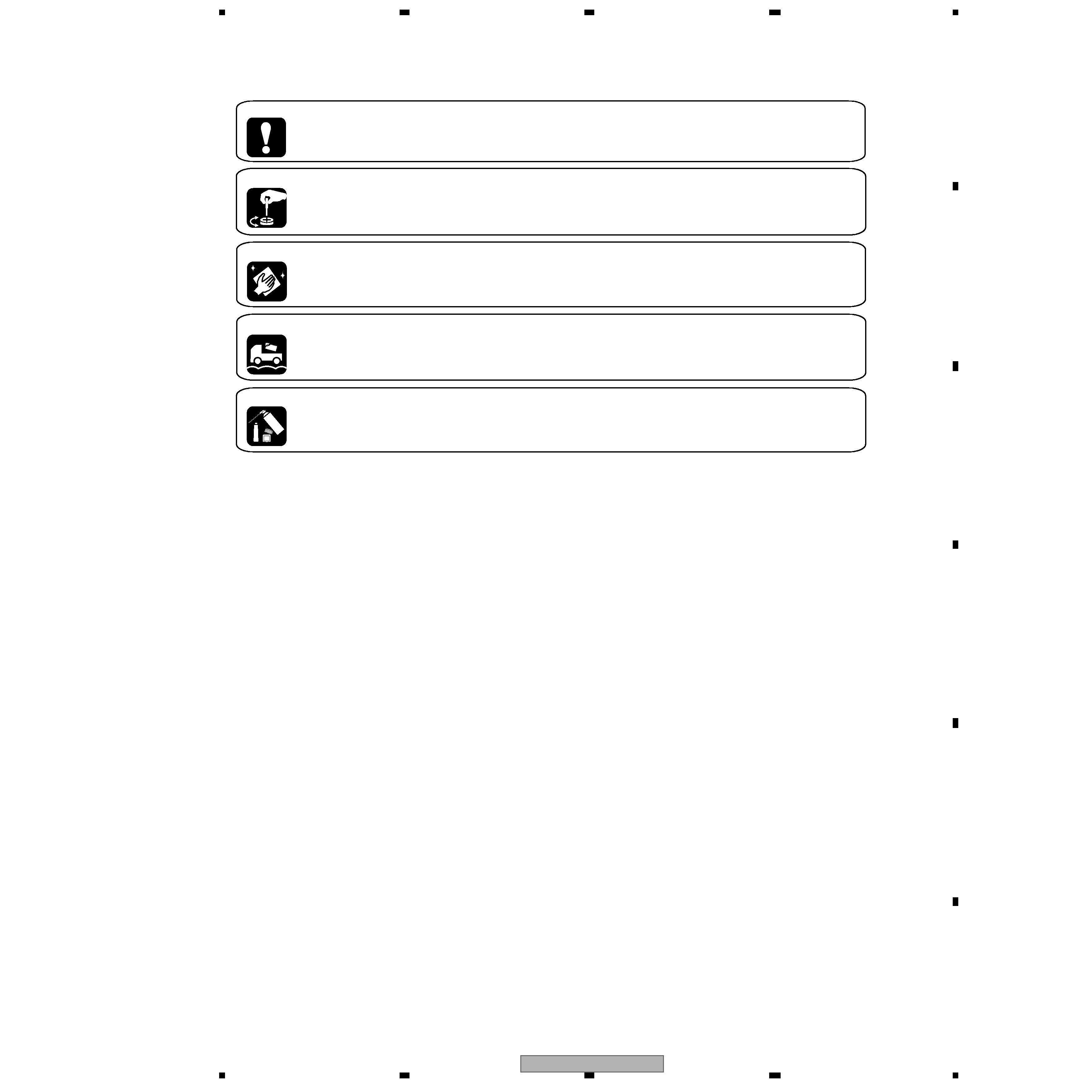
[ Important symbols for good services ]
In this manual, the symbols shown-below indicate that adjustments, settings or cleaning should be made securely.
When you find the procedures bearing any of the symbols, be sure to fulfill them:
2. Adjustments
To keep the original performances of the product, optimum adjustments or specification confirmation is indispensable.
In accordance with the procedures or instructions described in this manual, adjustments should be performed.
3. Cleaning
For optical pickups, tape-deck heads, lenses and mirrors used in projection monitors, and other parts requiring cleaning,
proper cleaning should be performed to restore their performances.
5. Lubricants, glues, and replacement parts
Appropriately applying grease or glue can maintain the product performances. But improper lubrication or applying
glue may lead to failures or troubles in the product. By following the instructions in this manual, be sure to apply the
prescribed grease or glue to proper portions by the appropriate amount.For replacement parts or tools, the prescribed
ones should be used.
4. Shipping mode and shipping screws
To protect the product from damages or failures that may be caused during transit, the shipping mode should be set or
the shipping screws should be installed before shipping out in accordance with this manual, if necessary.
1. Product safety
You should conform to the regulations governing the product (safety, radio and noise, and other regulations), and
should keep the safety during servicing by following the safety instructions described in this manual.

DRM-3000
4
1234
123
4
C
D
F
A
B
E
3.4 OVERALL WIRING DIAGRAM (3/3) ........................................................................................................ 48
3.5 ACFB UNIT .............................................................................................................................................. 53
3.6 PFCB UNIT .............................................................................................................................................. 54
3.7 POWER SUPPLY ASSY (DWR1367) ...................................................................................................... 55
3.8 POWER SUPPLY ASSY (DWR1368) ...................................................................................................... 56
3.9 POWER SUPPLY ASSY (DWR1369) ...................................................................................................... 57
3.10 PIF and PIF2 UNITS .............................................................................................................................. 58
3.11 MMCB UNIT (1/3) .................................................................................................................................. 60
3.12 MMCB UNIT (2/3) and FCNB UNITS..................................................................................................... 62
3.13 MMCB UNIT (3/3) .................................................................................................................................. 64
3.14 TMNB and IDSB UNITS ......................................................................................................................... 65
3.15 MIF2F, TMRB1, TMRB2 and TMRB3 UNITS ......................................................................................... 66
3.16 MIF1R, TMRB4, TMRB5, TMRB6 and TMRB7 UNITS .......................................................................... 67
3.17 DIFB3 UNIT ........................................................................................................................................... 68
3.18 DIFB4 UNIT ........................................................................................................................................... 70
3.19 VMDB (1/3) and ENCB UNITS............................................................................................................... 72
3.20 VMDB (2/3) UNIT ................................................................................................................................... 74
3.21 VMDB (3/3),CNNB,SIFB1,MDOT1,MDOT2,MDOR1,MDOR2 and SIFB2 UNITS.................................. 76
3.22 HMIF, TMRB8, MSTB, HMGB and MSDB UNITS .................................................................................. 78
3.23 DCMB1, UPSE, DNSE, DCMB2 and DSEB UNITS............................................................................... 80
3.24 FRPB UNIT ............................................................................................................................................ 82
4. PCB CONNECTION DIAGRAM ..................................................................................................................... 83
4.1 ACFB and PFCB UNITS .......................................................................................................................... 84
4.2 PIF1 and PIF2 UNITS .............................................................................................................................. 86
4.3 MMCB, FCNB, TMNB and IDSB UNITS .................................................................................................. 88
4.4 MIF2F, TMRB1, TMRB2 and TMRB3 UNITS ........................................................................................... 92
4.5 MIF1R, TMRB4, TMRB5, TMRB6 and TMRB7 UNITS ............................................................................ 94
4.6 DIFB3 UNIT ............................................................................................................................................. 96
4.7 DIFB4 UNIT ............................................................................................................................................. 98
4.8 VMDB, ENCB and CNNB UNITS ........................................................................................................... 100
4.9 SIFB, MDOT1, MDOT2, MDOR1, MDOR2 and SIFB2 UNITS .............................................................. 102
4.10 HMIF, TMRB8, MSTB, HMGB and MSDB UNITS ................................................................................ 103
4.11 DCMB1, UPSE, DNSE, DCMB2 and DSEB UNITS............................................................................. 104
4.12 FRPB UNIT .......................................................................................................................................... 106
5. PCB PARTS LIST ......................................................................................................................................... 107
6. ADJUSTMENT ............................................................................................................................................. 115
6.1 MECHANISM ADJUSTMENT ................................................................................................................ 115
6.1.1 Tools for Adjustment ........................................................................................................................ 115
6.1.2 Preparations for Adjustment ............................................................................................................ 115
6.1.3 Adjustment Methods ........................................................................................................................ 115
6.2 ADJUSTMENT FOR MECHANICAL OPERATIONS.............................................................................. 116
6.2.1 Height Adjustment of the D Guides L and R.................................................................................... 116
6.2.2 Right and Left Adjustment of the Carriage Base ............................................................................. 116
6.2.3 Front-Rear Adjustment of the Carriage Base .................................................................................. 117
6.2.4 Height Adjustment of the Interrupter UP.......................................................................................... 118
6.2.5 Phase Adjustment of the UP-DN Interrupters.................................................................................. 119
6.2.6 Verification of Operations After Adjustments ................................................................................... 119
6.3 SENSITIVITY ADJUSTMENT OF THE CARRIAGE-BASE DISC SENSOR.......................................... 120
6.4 SENSITIVITY ADJUSTMENT OF THE MAGAZINE DISC OUT-OF-POSITION SENSOR.................... 121
6.5 ELEVATING SPEED ADJUSTMENT ..................................................................................................... 122
6.6 LCD POWER SUPPLY VOLTAGE ADJUSTMENT................................................................................. 123
7. GENERAL INFORMATION ........................................................................................................................... 124
7.1 DIAGNOSIS ........................................................................................................................................... 124
7.1.1 SYSTEM ADMINISTRATOR MODE ................................................................................................ 124
7.1.2 TEST MODE .................................................................................................................................... 126
7.1.3 TROUBLESHOOTING ..................................................................................................................... 130
7.1.4 Physical Addresses ......................................................................................................................... 146
7.1.5 SCSI SENSE CODE........................................................................................................................ 147
7.1.6 CHANGER DIAGNOSIS PROGRAM "Diagnose V"......................................................................... 148
7.1.7 PCB LOCATION .............................................................................................................................. 150
7.1.8 DISASSEMBLY................................................................................................................................ 151
7.1.9 INFORMATION ON MAINTENANCE .............................................................................................. 157
7.2 PARTS.................................................................................................................................................... 159
7.2.1 IC INFORMATION ........................................................................................................................... 159
8. PANEL FACILITIES ...................................................................................................................................... 162

DRM-3000
5
5
678
56
7
8
C
D
F
A
B
E
1. SPECIFICATIONS
[ 300 DISC CHANGER ]
Description ............................................... 700 disc changer
Power supply ............................. AC 100V-240V, 50/60 Hz
Power consumption ................... Maximum of 3.3A (300 W)
Weight of main unit (including placement fixtures)
60.6 kg
(133 lb 10oz)
External dimensions (including placement fixtures)
760 x 729 x 872 mm (W x D x H)
29-15/16 x 28-11/16 x 34-5/16in (W x D x H)
Operating requirements * .......................... +5
°C to +35°C
Humidity * ....................... 5% to 85% (with no condensation)
Storage requirements ................................ 40
°C to +60°C
* The figures for permissible operating temperature and humidity
may change depending on the components loaded. For details,
consult the operating instructions for each component used.
Functional specifications
Maximum number of discs ...................... 320 (12-cm discs)
Maximum number of disc magazines
50-disc magazines ....................................................... 6
20-disc hyper magazine ................................................ 1
Maximum number of drives .............................................. 8
Items included
20-disc hyper magazine ................................................... 1
Changer/drive SCSI cable ................................................. 1
Power cord (for use in Canada and USA) ........................ 1
Power cord (for use in Japan) .......................................... 1
Base stabilizer ................................................................... 2
Screw for use in attaching Base stabilizer ........................ 6
Lock release key .............................................................. 2
Operations Instructions ..................................................... 1
¶The external design of this product or any of the above
specifications may be changed at any time without prior
notification.
SCSI connector specifications
1) Pin layout of SCSI connectors
NOTES:
¶ Pin No. 12 to 14, 37 and 39 are not grounded.
¶ The connectors are of the shielded type.
¶ For details on the control commands, refer to the separate
specifications manual.
2) Electrical specifications of SCSI
GROUND
GROUND
GROUND
GROUND
GROUND
GROUND
GROUND
GROUND
GROUND
GROUND
GROUND
NC
NC
NC
GROUND
GROUND
GROUND
GROUND
GROUND
GROUND
GROUND
GROUND
GROUND
GROUND
GROUND
1
2
3
4
5
6
7
8
9
10
11
12
13
14
15
16
17
18
19
20
21
22
23
24
25
26
27
28
29
30
31
32
33
34
35
36
37
38
39
40
41
42
43
44
45
46
47
48
49
50
DB(0)
-DB(1)
-DB(2)
-DB(3)
-DB(4)
-DB(5)
-DB(6)
-DB(7)
-DB(P)
GROUND
GROUND
NC
TERMPWR
NC
GROUND
-ATN
GROUND
-BSY
-ACK
-RST
-MSG
-SEL
-C/D
-REQ
-I/O
Signal name
Pin No.
Signal name
Output
characteristics
Input
characteristics
The signals driven by SCSI equipment
present the following output characteristics.
True (LOW):
VOL = 0.0 to 0.4 V DC
IOL = 48 mA (0.5 V DC) max.
False (HIGH): VOH = 2.5 to 5.25 V DC
The signals driven by SCSI equipment
present the following input characteristics.
True (LOW):
VOL = 0.0 to 0.4 V DC
IOL = -0.4 mA (0.4 V DC) max.
False (HIGH): VOH = 2.0 to 5.25 V DC
NOTES:
¶ As the SCSI interface is of the single-ended type, it should be
terminated on both ends of the cable.
¶ The maximum recommended length of an SCSI cable is 6
meters (20 feet) (including internal wiring).
1
¡
±
+
Base stabilizer ... x 2
(DNH2385)
Lock release key ... x 2
(DXC1006)
Power cord
(for use in Canada and USA) ... x 1
(DDG1071)
Power cord
(for use in Japan) ... x 1
(DDG1047)
Changer/drive
SCSI cable ... x 1
(DDC1006)
20 disc hyper
mahazine ... x 1
[ Accessories ]
This type of power cord is for use
in America and Canada only.
Do use this power cord in places
other than America or Canada.
This type of power cord is for use
in Japan only.
Do not use this power cord in a
places other than Japan.
Screw for use in attaching
placement fixtures ............ x 6
Operating instructions ....... x 1
Warranty ........................... x 1
Service network sheet ...... x 1