ORDER NO.
CRT3544
RX350
AUDIO SYSTEM
HEAD UNIT
CRT3544
PUB.NO.
Manufactured for TOYOTA
by PIONEER CORPORATION
VEHICLE
DESTINATION
PRODUCED
AFTER
OEM PARTS No.
ID No.
PIONEER MODEL No.
RX350
U.S.A., CANADA
January 2006
86120-48A00
P1806
DEX-MG8167ZT/UC
RX350
U.S.A., CANADA
January 2006
86120-48C20
P1806
DEX-MG8167ZT-91/UC
RX350
U.S.A., CANADA
January 2006
86120-48A10
P1805
DEX-MG8667ZT/UC
RX350
U.S.A., CANADA
January 2006
86120-48C30
P1805
DEX-MG8667ZT-91/UC
RX350
U.S.A., CANADA
January 2006
86120-0E030
AP1811
DEX-MG8167ZT/X1HUC
RX350
U.S.A., CANADA
January 2006
86120-0E090
AP1811
DEXG8167ZT91/X1HUC
RX350
U.S.A., CANADA
January 2006
86120-0E040
AP1810
DEX-MG8667ZT/X1HUC
RX350
U.S.A., CANADA
January 2006
86120-0E100
AP1810
DEXG8667ZT91/X1HUC
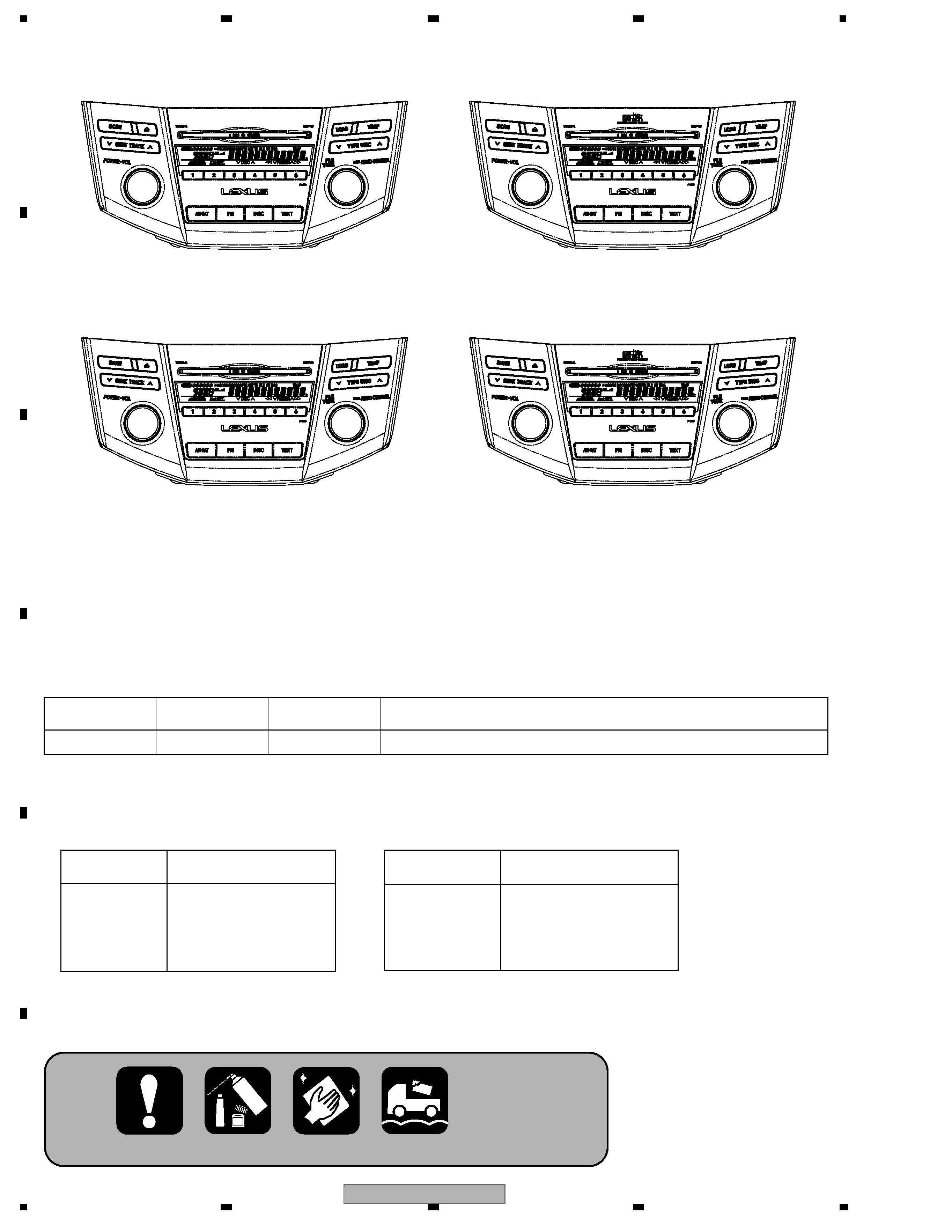
DEX-MG8167ZT/UC
2
12
34
12
3
4
C
D
F
A
B
E
DEX-MG8167ZT/UC
This service manual should be used together with the following manual(s):
DEX-MG8167ZT/UC
ID No. P1806
DEX-MG8667ZT/UC
ID No. P1805
DEX-MG8167ZT/X1HUC
ID No. AP1811
DEX-MG8667ZT/X1HUC
ID No. AP1810
Model No.
Order No.
Mech.Module
Remarks
CX-3168
CRT3467
G3
CD Mech. Module : Circuit Over View, Mech. Over View, Disassembly, How To Assemble
For details, refer to "Important Check Points for Good Servicing".
Supplementary model is identical to the original except for the addition of following items.
*:Non spare part
Description
DEX-MG8167ZT-91/UC
DEX-MG8667ZT-91/UC
Cover
CEG1045 (x2)
Cover
CEG1325
Carton
CHG4861
Contain Box
CHL4861 (x1/2)
Air Cap
* CHW1945
Description
DEXG8167ZT91/X1HUC
DEXG8667ZT91/X1HUC
Polyethylene Bag * HEG0036
Cover
* HEG0037
Carton
HHG0432
Protector
HHP0248
Protector
HHP0270
DEX-MG8167ZT/UC
3
56
7
8
56
7
8
C
D
F
A
B
E
SAFETY INFORMATION
CAUTION
This service manual is intended for qualified service technicians; it is not meant for the casual do-it-yourselfer.
Qualified technicians have the necessary test equipment and tools, and have been trained to properly and safely repair
performed
can adversely affect the
and reliability of the product and may void the
.
If you are not qualified to
the repair of this product properly and
, you should not risk trying to do so
and refer the repair to a qualified service technician.
WARNING
W
W
This product contains lead in solder and certain electrical parts contain chemicals which are known to the state of
California to cause cancer
Health & Safety Code Section 25249.6 - Proposition 65
CD MECHANISM MODULE section precaution
1. Before disassembling the unit, be sure to turn off the power. Unplugging and plugging the connectors
during power-on mode may damage the ICs inside the unit.
2. To protect the pickup unit from electrostatic discharge during servicing, take an appropriate treatment
(shorting-solder) by referring to "the DISASSEMBLY" .
- Service Precautions
1. You should conform to the regulations governing the product (safety, radio and noise, and other regulations),
and should keep the safety during servicing by following the safety instructions described in this manual.
2. Make sure to install grille when charging power.
(*If you fail to do so, the main body will identify it as "a model without display" and the button will not function. )
DEX-MG8167ZT/UC
4
12
34
12
3
4
C
D
F
A
B
E
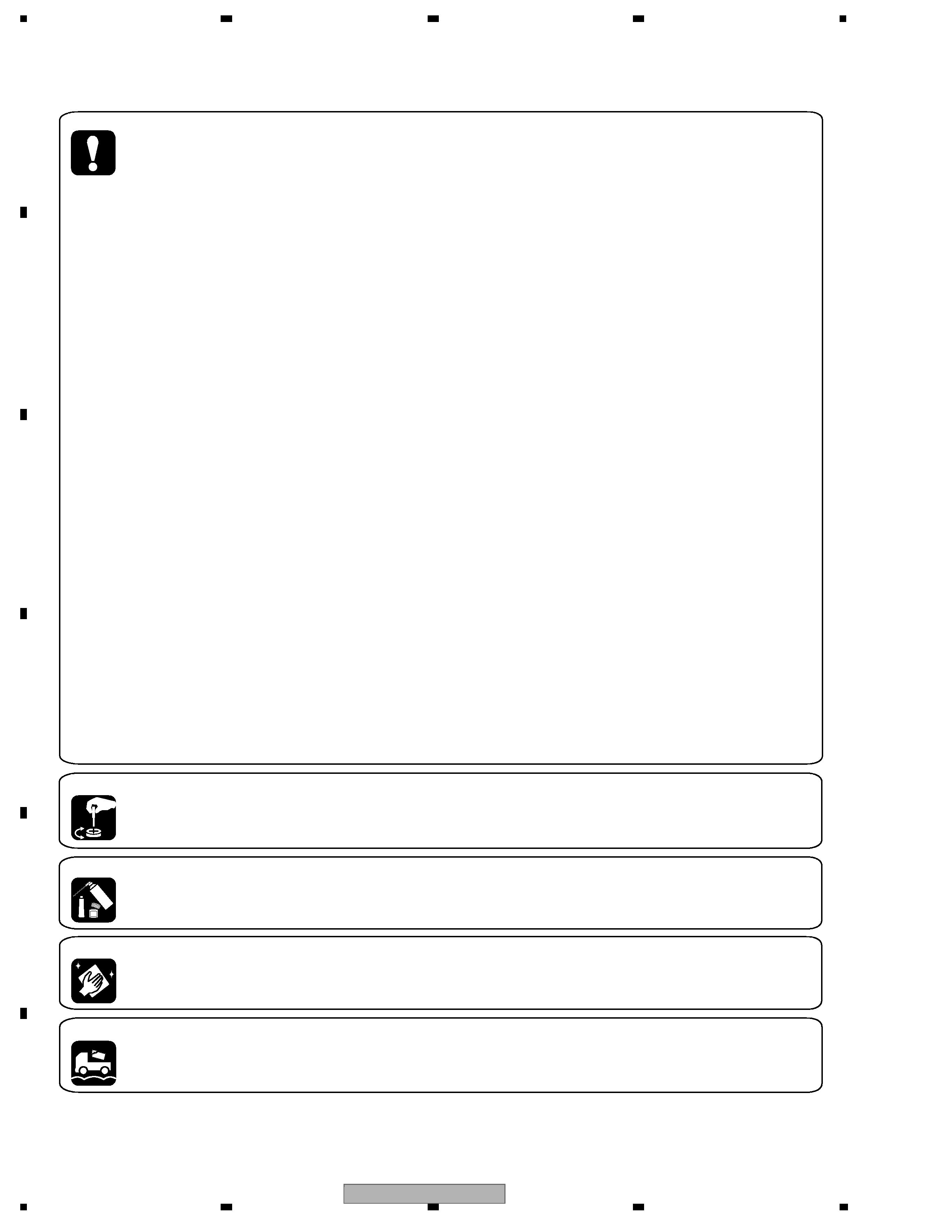
[Important Check Points for Good Servicing]
In this manual, procedures that must be performed during repairs are marked with the below symbol.
Please be sure to confirm and follow these procedures.
1. Product safety
Please conform to product regulations (such as safety and radiation regulations), and maintain a safe servicing environment by
following the safety instructions described in this manual.
1 Use specified parts for repair.
Use genuine parts. Be sure to use important parts for safety.
2 Do not perform modifications without proper instructions.
Please follow the specified safety methods when modification(addition/change of parts) is required due to interferences such as
radio/TV interference and foreign noise.
3 Make sure the soldering of repaired locations is properly performed.
When you solder while repairing, please be sure that there are no cold solder and other debris.
Soldering should be finished with the proper quantity. (Refer to the example)
4 Make sure the screws are tightly fastened.
Please be sure that all screws are fastened, and that there are no loose screws.
5 Make sure each connectors are correctly inserted.
Please be sure that all connectors are inserted, and that there are no imperfect insertion.
6 Make sure the wiring cables are set to their original state.
Please replace the wiring and cables to the original state after repairs.
In addition, be sure that there are no pinched wires, etc.
7 Make sure screws and soldering scraps do not remain inside the product.
Please check that neither solder debris nor screws remain inside the product.
8 There should be no semi-broken wires, scratches, melting, etc. on the coating of the power cord.
Damaged power cords may lead to fire accidents, so please be sure that there are no damages.
If you find a damaged power cord, please exchange it with a suitable one.
9 There should be no spark traces or similar marks on the power plug.
When spark traces or similar marks are found on the power supply plug, please check the connection and advise on secure
connections and suitable usage. Please exchange the power cord if necessary.
0 Safe environment should be secured during servicing.
When you perform repairs, please pay attention to static electricity, furniture, household articles, etc. in order to prevent injuries.
Please pay attention to your surroundings and repair safely.
2. Adjustments
To keep the original performance of the products, optimum adjustments and confirmation of characteristics within specification.
Adjustments should be performed in accordance with the procedures/instructions described in this manual.
4. Cleaning
For parts that require cleaning, such as optical pickups, tape deck heads, lenses and mirrors used in projection monitors, proper
cleaning should be performed to restore their performances.
3. Lubricants, Glues, and Replacement parts
Use grease and adhesives that are equal to the specified substance.
Make sure the proper amount is applied.
5. Shipping mode and Shipping screws
To protect products from damages or failures during transit, the shipping mode should be set or the shipping screws should be
installed before shipment. Please be sure to follow this method especially if it is specified in this manual.

DEX-MG8167ZT/UC
5
56
7
8
56
7
8
C
D
F
A
B
E
CONTENTS
SAFETY INFORMATION......................................................................................................................................3
1. SPECIFICATIONS .............................................................................................................................................6
2. EXPLODED VIEWS AND PARTS LIST.............................................................................................................7
2.1 EXTERIOR(1) .............................................................................................................................................8
2.2 EXTERIOR(2) ...........................................................................................................................................10
2.3 CD MECHANISM MODULE .....................................................................................................................12
3. BLOCK DIAGRAM AND SCHEMATIC DIAGRAM ..........................................................................................14
3.1 BLOCK DIAGRAM ....................................................................................................................................14
3.2 MAIN UNIT(1/3)(GUIDE PAGE)................................................................................................................20
3.3 MAIN UNIT(2/3)(GUIDE PAGE)................................................................................................................26
3.4 MAIN UNIT(3/3) ........................................................................................................................................32
3.5 KEYBOARD PCB .....................................................................................................................................34
3.6 CD MECHANISM MODULE .....................................................................................................................36
3.7 L PCB .......................................................................................................................................................46
3.8 R PCB.......................................................................................................................................................47
4. PCB CONNECTION DIAGRAM ......................................................................................................................48
4.1 MAIN UNIT ...............................................................................................................................................48
4.2 KEYBOARD PCB .....................................................................................................................................52
4.3 CONTROL UNIT.......................................................................................................................................56
4.4 RPS PCB ASSY .......................................................................................................................................58
4.5 L PCB .......................................................................................................................................................59
4.6 R PCB.......................................................................................................................................................60
5. ELECTRICAL PARTS LIST .............................................................................................................................61
6. ADJUSTMENT ................................................................................................................................................71
6.1 JIG CONNECTION DIAGRAM .................................................................................................................71
6.2 CD ADJUSTMENT ...................................................................................................................................73
6.3 ERROR MODE .........................................................................................................................................77
7. GENERAL INFORMATION .............................................................................................................................81
7.1 DIAGNOSIS ..............................................................................................................................................81
7.1.1 AVC-LAN DIAGNOSIS MODE...............................................................................................................81
7.1.2 DISASSEMBLY......................................................................................................................................87
7.1.3 CONNECTOR FUNCTION DESCRIPTION ..........................................................................................90
7.2 PARTS ......................................................................................................................................................91
7.2.1 IC ...........................................................................................................................................................91
7.2.2 DISPLAY ..............................................................................................................................................100
7.3 EXPLANATION .......................................................................................................................................101
7.3.1 OPERATIONAL FLOW CHART ...........................................................................................................101
7.3.2 SYSTEM BLOCK DIAGRAM ...............................................................................................................102
8. OPERATIONS ...............................................................................................................................................103