PIONEER CORPORATION
4-1, Meguro 1-Chome, Meguro-ku, Tokyo 153-8654, Japan
PIONEER ELECTRONICS SERVICE INC.
P.O.Box 1760, Long Beach, CA 90801-1760 U.S.A.
PIONEER EUROPE N.V.
Haven 1087 Keetberglaan 1, 9120 Melsele, Belgium
PIONEER ELECTRONICS ASIACENTRE PTE.LTD. 253 Alexandra Road, #04-01, Singapore 159936
C PIONEER CORPORATION 2000
K-ZZY. FEB. 2000 Printed in Japan
ORDER NO.
CRT2477
MULTI-CD CONTROL HIGH POWER CD PLAYER WITH FM/AM TUNER
DEH-P720
X1N/UC
Service
Manual
CONTENTS
1. SAFETY INFORMATION ............................................2
2. EXPLODED VIEWS AND PARTS LIST .......................2
3. BLOCK DIAGRAM AND SCHEMATIC DIAGRAM ...10
4. PCB CONNECTION DIAGRAM ................................28
5. ELECTRICAL PARTS LIST ........................................39
6. ADJUSTMENT..........................................................47
7. GENERAL INFORMATION .......................................52
7.1 DIAGNOSIS ........................................................52
7.1.1 TEST MODE ..............................................52
7.1.2 DISASSEMBLY .........................................56
7.2 IC ........................................................................61
7.3 OPERATIONAL FLOW CHART ...........................69
8. OPERATIONS AND SPECIFICATIONS.....................70
DEH-P7200
X1N/UC
DEH-P720/X1N/UC
- This service manual should be used together with the following manual(s):
Model No.
Order No.
Mech. Module Remarks
CX-958
CRT2423
S8.1
CD Mech. Module:Circuit Description, Mech.Description, Disassembly
2
DEH-P720,P7200
- CD Player Service Precautions
1. For pickup unit(CXX1285) handling, please refer
to"Disassembly"(see page 56).
During replacement, handling precautions shall be
taken to prevent an electrostatic discharge(protection
by a short pin).
2. During disassembly, be sure to turn the power off
since an internal IC might be destroyed when a con-
nector is plugged or unplugged.
3. Please checking the grating after changing the ser-
vice pickup unit(see page 49).
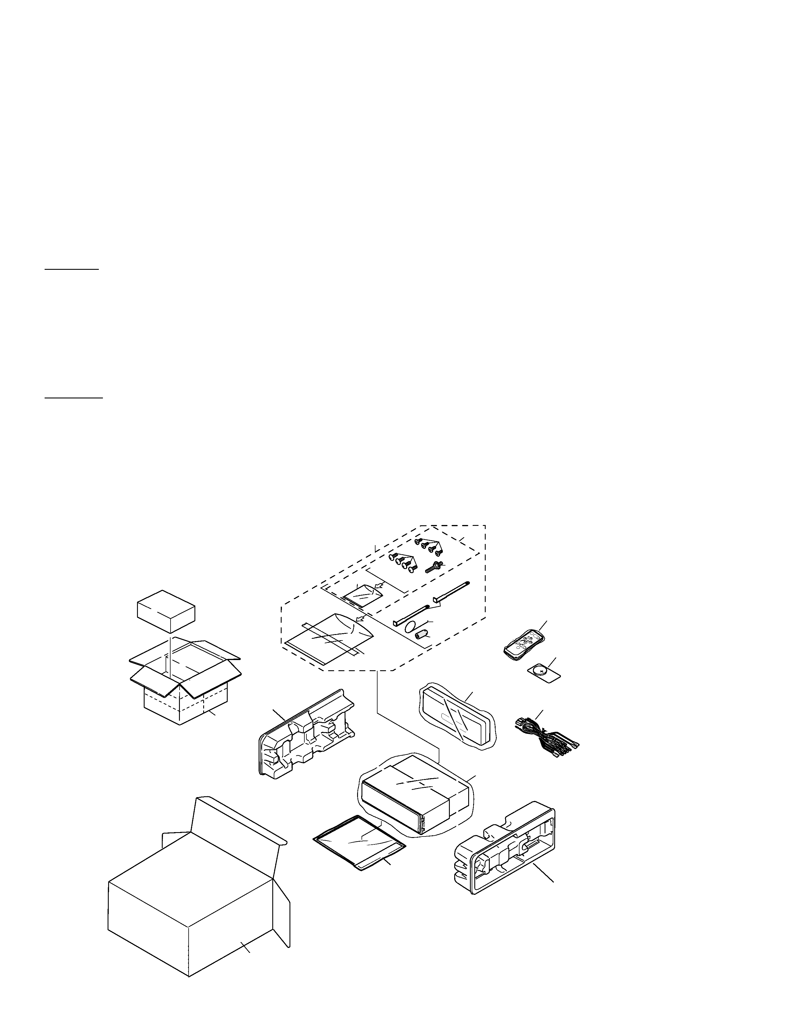
2. EXPLODED VIEWS AND PARTS LIST
2.1 PACKING
CAUTION
This service manual is intended for qualified service technicians; it is not meant for the casual do-it-yourselfer.
Qualified technicians have the necessary test equipment and tools, and have been trained to properly and safely repair
complex products such as those covered by this manual.
Improperly performed repairs can adversely affect the safety and reliability of the product and may void the warranty.
If you are not qualified to perform the repair of this product properly and safely; you should not risk trying to do so
and refer the repair to a qualified service technician.
WARNING
This product contains lead in solder and certain electrical parts contain chemicals which are known to the state of
California to cause cancer, birth defects or other reproductive harm.
Health & Safety Code Section 25249.6 - Proposition 65
1. SAFETY INFORMATION
19
18
15
13
17
16
5
8
12
4
11
10
9
7
6
3
1
2
14
20
3
DEH-P720,P7200
1 Carton(P720)
CHG4009
Carton(P7200)
CHG4008
2 Cord Assy(P720)
CDE6241
Cord Assy(P7200)
CDE6291
*
3 Accessory Assy
CEA2395
4 Spring
CBH1650
*
5 Screw Assy
CEA2396
6 Screw
CBA1002
*
7 Polyethylene Bag
CEG-127
8 Screw
CRZ50P090FMC
9 Screw
TRZ50P080FMC
*
10 Polyethylene Bag
CEG-158
11 Handle
CNC5395
12 Bush
CNV3930
13 Polyethylene Bag
CEG1173
14 Battery(P720)
CEX1006
15 Contain Box(P720)
CHL4009
Contain Box(P7200)
CHL4008
16 Protector
CHP2251
17 Protector
CHP2252
18 Case Assy
CXB3520
19-1 Polyethylene Bag
CEG1116
19-2 Owner's Manual(P720)
CRD3172
Owner's Manual(P7200)
CRD3174
19-3 Installation Manual(P720) CRD3173
Installation Manual(P7200)CRD3175
*
19-4 Warranty Card
CRY1070
*
19-5 Card(P7200)
ARY1048
*
19-6 Warranty Card
CRP1207
20 Remote Control Assy(P720) CXB4285
Mark No. Description
Part No.
Mark No. Description
Part No.
- PACKING SECTION PARTS LIST
NOTE:
- Parts marked by "*" are generally unavailable because they are not in our Master Spare Parts List.
- Screws adjacent to
mark on the product are used for disassembly.
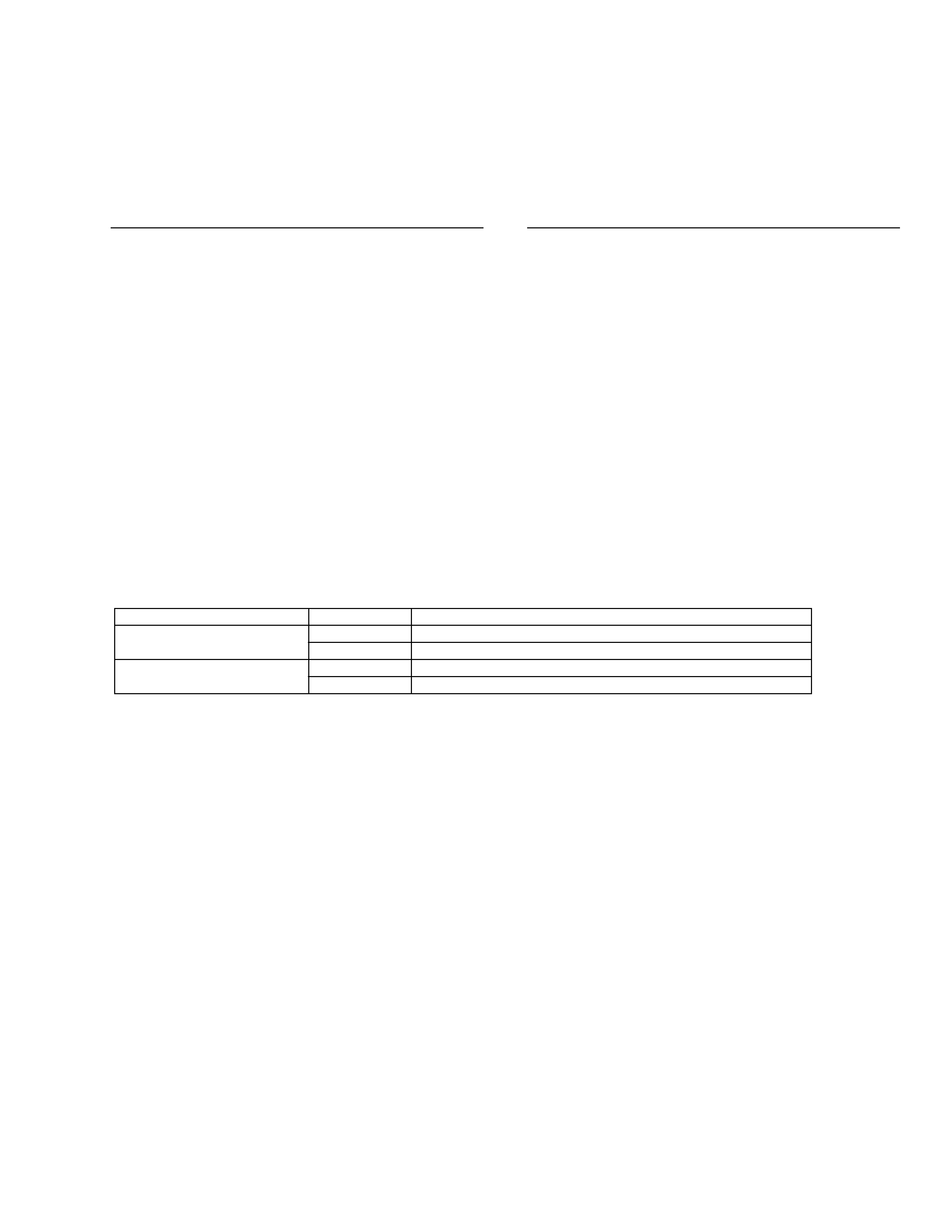
- Owner's Manual, Installation Manual
Model
Part No.
Language
DEH-P720/X1N/UC
CRD3172
English, French
CRD3173
English, French
DEH-P7200/X1N/UC
CRD3174
English, French
CRD3175
English, French
4
DEH-P720,P7200
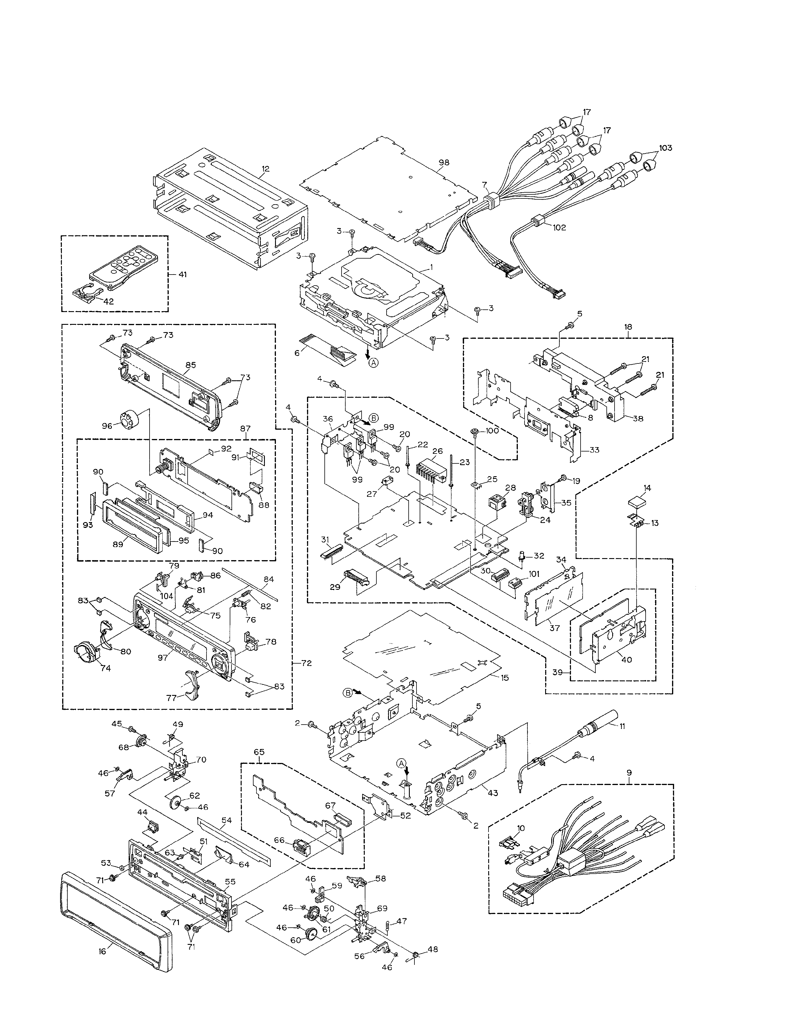
2.2 EXTERIOR

DEH-P720,P7200
1 CD Mechanism Module(S8.1) CXK5202
2 Screw
BMZ30P040FZK
3 Screw
BSZ26P060FMC
4 Screw
BSZ30P060FMC
5 Screw
BSZ30P100FMC
6 Cable
CDE6164
7 Cord Assy
See Contrast table(2)
8 IC(IC301)
PAL005A
9 Cord Assy
CDE6241
10 Fuse(10A)
CEK1136
11 Antenna Cable
CDH1266
12 Holder
CNC6798
13 Holder
CNC8357
14 Spacer
CNM6482
15 Insulator
CNM6606
16 Panel
CNS5992
17 Cap
See Contrast table(2)
18 Tuner Amp Unit
See Contrast table(2)
19 Screw
BPZ26P060FMC
20 Screw
BSZ26P060FMC
21 Screw
BSZ26P160FMC
22 Clamper
See Contrast table(2)
23 Clamper
CEF1009
24 Pin Jack(CN351)
CKB1028
25 Terminal(CN402)
CKF1059
26 Plug(CN901)
See Contrast table(2)
*
27 Plug(CN451)
CKS1052
28 Connector(CN101)
CKS3408
29 Plug(CN801)
CKS3537
30 Connector(CN361)
See Contrast table(2)
31 Connector(CN651)
CKS3842
32 Pin Jack(CN401)
CKX1046
33 Panel
See Contrast table(2)
34 Holder
CNC7533
35 Holder
CNC8298
36 Holder
CNC8615
37 Insulator
CNM5967
38 Heat Sink
CNR1550
39 FM/AM Tuner Unit
CWE1501
40 Holder
CNC7532
41 Remote Control Assy
See Contrast table(2)
42 Battery Cover
See Contrast table(2)
43 Chassis Unit
CXB5063
44 Button(EJECT)
CAC6428
45 Screw(M2x2)
CBA1176
46 Washer
CBF1038
47 Spring
CBH2310
48 Spring
CBH2312
49 Spring
CBH2313
50 Spring
CBH2393
51 Spring
CBL1492
52 Holder
CNC8616
53 Cushion
CNM5486
54 Cover
CNM6854
55 Panel
CNS5791
56 Arm
CNV5991
57 Arm
CNV5992
58 Arm
CNV5993
59 Lever
CNV5994
60 Gear
CNV5995
61 Gear
CNV5996
62 Gear
CNV5997
63 Pin
CNV6027
64 Lighting Conductor
CNV6069
65 Panel PCB Unit
CWM7157
66 Socket(CN902)
CKS3550
67 Connector(CN903)
CKS4206
68 Damper Unit
CXB5070
69 Holder Unit
CXB5736
70 Holder Unit
CXB5737
71 Screw
IMS20P045FZK
72 Detach Grille Assy
See Contrast table(2)
73 Screw
BPZ20P100FZK
74 Knob
CAA1525
75 Button(SOURCE)
CAC6331
76 Button(OPEN)
CAC6333
77 Button(F,A)
CAC6337
78 Button(BAND)
CAC6442
79 Button(E)
CAC6464
80 Button(DISP)
CAC6340
81 Spring
CBH2316
82 Spring
CBH2320
83 Cushion
CNM6542
84 Spacer
CNM6871
85 Cover
CNS5737
86 Holder
CNV6177
87 Keyboard Unit
CWM7268
88 Connector(CN1901)
CKS4205
89 Holder
CNC8698
90 Cushion
CNM6633
91 Spacer
CNM6710
92 Spacer
CNM6711
93 Sheet
CNM6746
94 Holder
CNV6105
95 OEL Unit
MXR8004
96 Knob Unit
CXB5350
97 Grille Unit
See Contrast table(2)
98 Case Unit
CXB5788
99 Transistor(Q831,Q921,Q998) 2SD2396
100 Screw
ISS26P055FUC
101 Connectot(CN361)
See Contrast table(2)
102 Cord Assy
See Contrast table(2)
103 Cap
See Contrast table(2)
104 Double Sided Tape
CNM6811
(1) EXTERIOR SECTION PARTS LIST
Mark No. Description
Part No.
Mark No. Description
Part No.
5