PIONEER ELECTRONIC CORPORATION
4-1, Meguro 1-Chome, Meguro-ku, Tokyo 153-8654, Japan
PIONEER ELECTRONICS SERVICE INC.
P.O.Box 1760, Long Beach, CA 90801-1760 U.S.A.
PIONEER ELECTRONIC [EUROPE] N.V.
Haven 1087 Keetberglaan 1, 9120 Melsele, Belgium
PIONEER ELECTRONICS ASIACENTRE PTE.LTD. 253 Alexandra Road, #04-01, Singapore 159936
C PIONEER ELECTRONIC CORPORATION 1998
K-ZZD. DEC. 1998 Printed in Japan
ORDER NO.
CRT2308
MULTI-CD CONTROL HIGH POWER CD PLAYER WITH FM/AM TUNER
DEH-P400
X
1N/UC
Service
Manual
CONTENTS
1. SAFETY INFORMATION ............................................2
2. EXPLODED VIEWS AND PARTS LIST .......................2
3. SCHEMATIC DIAGRAM ...........................................12
4. PCB CONNECTION DIAGRAM ................................34
5. ELECTRICAL PARTS LIST ........................................44
6. ADJUSTMENT..........................................................53
7. GENERAL INFORMATION .......................................57
7.1 PARTS .................................................................57
7.1.1 IC................................................................57
7.1.2 DISPLAY ....................................................64
7.2 DIAGNOSIS ........................................................65
7.2.1 DISASSEMBLY .........................................65
7.2.2 TEST MODE ..............................................66
7.3 BLOCK DIAGRAM ..............................................70
8. OPERATIONS AND SPECIFICATIONS.....................72
- See the separate manual CX-916(CRT2300) for the CD mechanism description, disassembly and circuit
description.
- The CD mechanism employed in this model is one of S8 series.
DEH-P4000
X
1N/UC
DEH-P4050
X
1N/ES
DEH-P400/X1N/UC
2
DEH-P400,P4000,P4050
- CD Player Service Precautions
1. For pickup unit(CXX1285) handling, please refer
to"Disassembly"(CX-916 Service Manual CRT2300).
During replacement, handling precautions shall be
taken to prevent an electrostatic discharge(protection
by a short pin).
2. During disassembly, be sure to turn the power off
since an internal IC might be destroyed when a con-
nector is plugged or unplugged.
3. Please checking the grating after changing the ser-
vice pickup unit(see page 55).
CAUTION
This service manual is intended for qualified service technicians; it is not meant for the casual do-it-yourselfer.
Qualified technicians have the necessary test equipment and tools, and have been trained to properly and safely repair
complex products such as those covered by this manual.
Improperly performed repairs can adversely affect the safety and reliability of the product and may void the warranty.
If you are not qualified to perform the repair of this product properly and safely; you should not risk trying to do so
and refer the repair to a qualified service technician.
WARNING
This product contains lead in solder and certain electrical parts contain chemicals which are known to the state of
California to cause cancer, birth defects or other reproductive harm.
Health & Safety Code Section 25249.6 - Proposition 65
1. SAFETY INFORMATION
2. EXPLODED VIEWS AND PARTS LIST
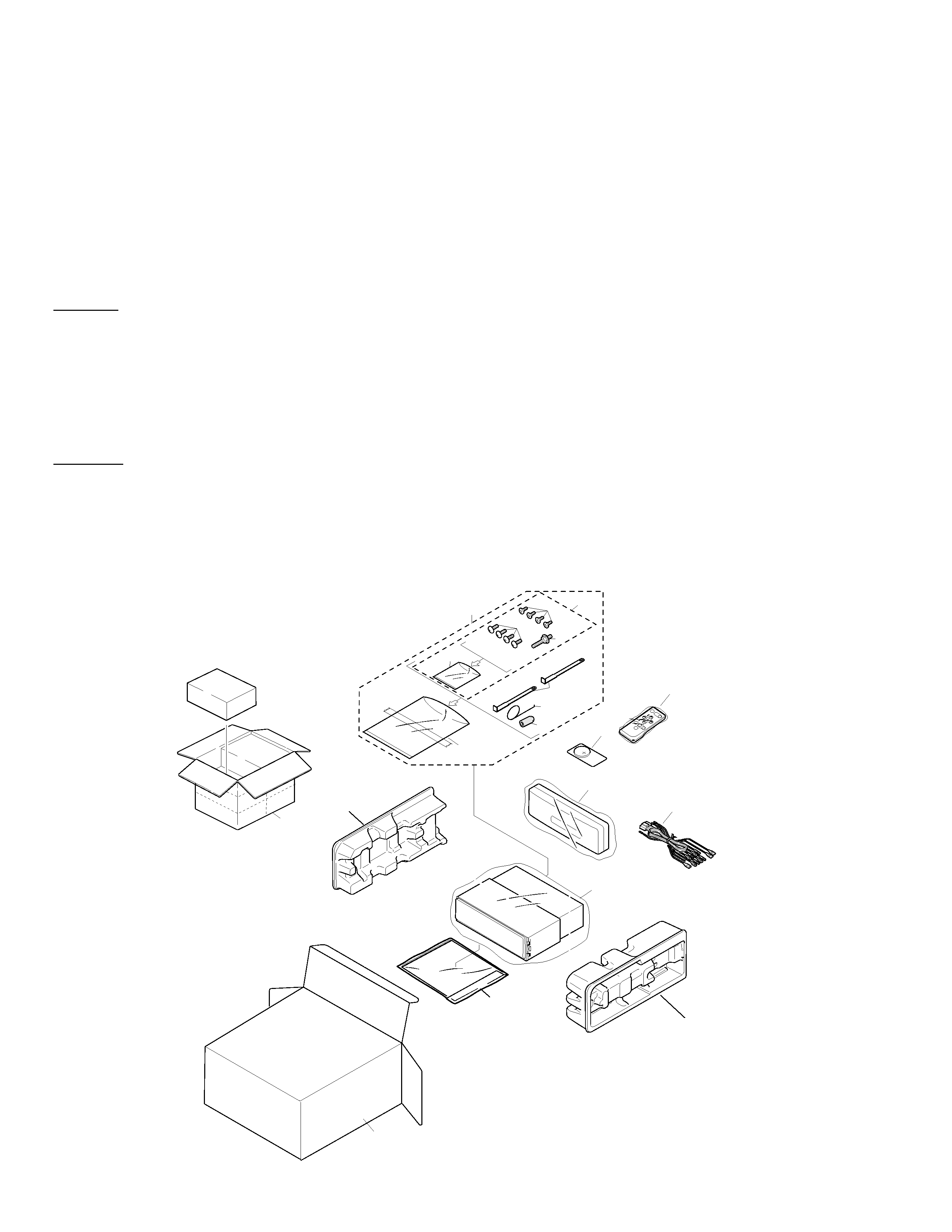
2.1 PACKING
20
19
15
12
16
17
4
7
11
3
10
9
8
6
5
2
14
18
13
1
- Owner's Manual
Model
Part No.
Language
DEH-P400/X1N/UC
CRD2822
English, French
DEH-P4000/X1N/UC
CRD2820
English, French
DEH-P4050/X1N/ES
CRD2832
English, Spanish, Portuguese
CRD2833
Arabic, Chinese
- Installation Manual
Model
Part No.
Language
DEH-P400/X1N/UC
CRD2823
English, French
DEH-P4000/X1N/UC
CRD2821
English, French
DEH-P4050/X1N/ES
CRD2834
English, Spanish, Portuguese, Arabic, Chinese
3
DEH-P400,P4000,P4050
1 Cord Assy
CDE5769
*
2 Accessory Assy
CEA2395
3 Spring
CBH1650
4 Screw Assy
CEA2396
5 Screw
CBA1002
*
6 Polyethylene Bag
CEG-127
7 Screw
CRZ50P090FMC
8 Screw
TRZ50P080FMC
*
9 Polyethylene Bag
CEG-158
10 Handle
CNC5395
11 Bush
CNV3930
12 Polyethylene Bag
See Contrast table(2)
13 Battery
CEX1030
14 Carton
See Contrast table(2)
15 Contain Box
See Contrast table(2)
16 Protector
CHP2101
17 Protector
CHP2102
18 Remote Control Unit
CXB3455
19 Case Assy
CXB3520
20-1 Owner's Manual
See Contrast table(2)
20-2 Owner's Manual
See Contrast table(2)
20-3 Installation Manual
See Contrast table(2)
* 20-4 Warranty Card
See Contrast table(2)
20-5 Polyethylene Bag
CEG1116
* 20-6 Card
See Contrast table(2)
* 20-7 Label
See Contrast table(2)
Mark No. Description
Part No.
Mark No. Description
Part No.
(1) PACKING SECTION PARTS LIST
NOTE:
- Parts marked by "*" are generally unavailable because they are not in our Master Spare Parts List.
- Screws adjacent to
mark on the product are used for disassembly.
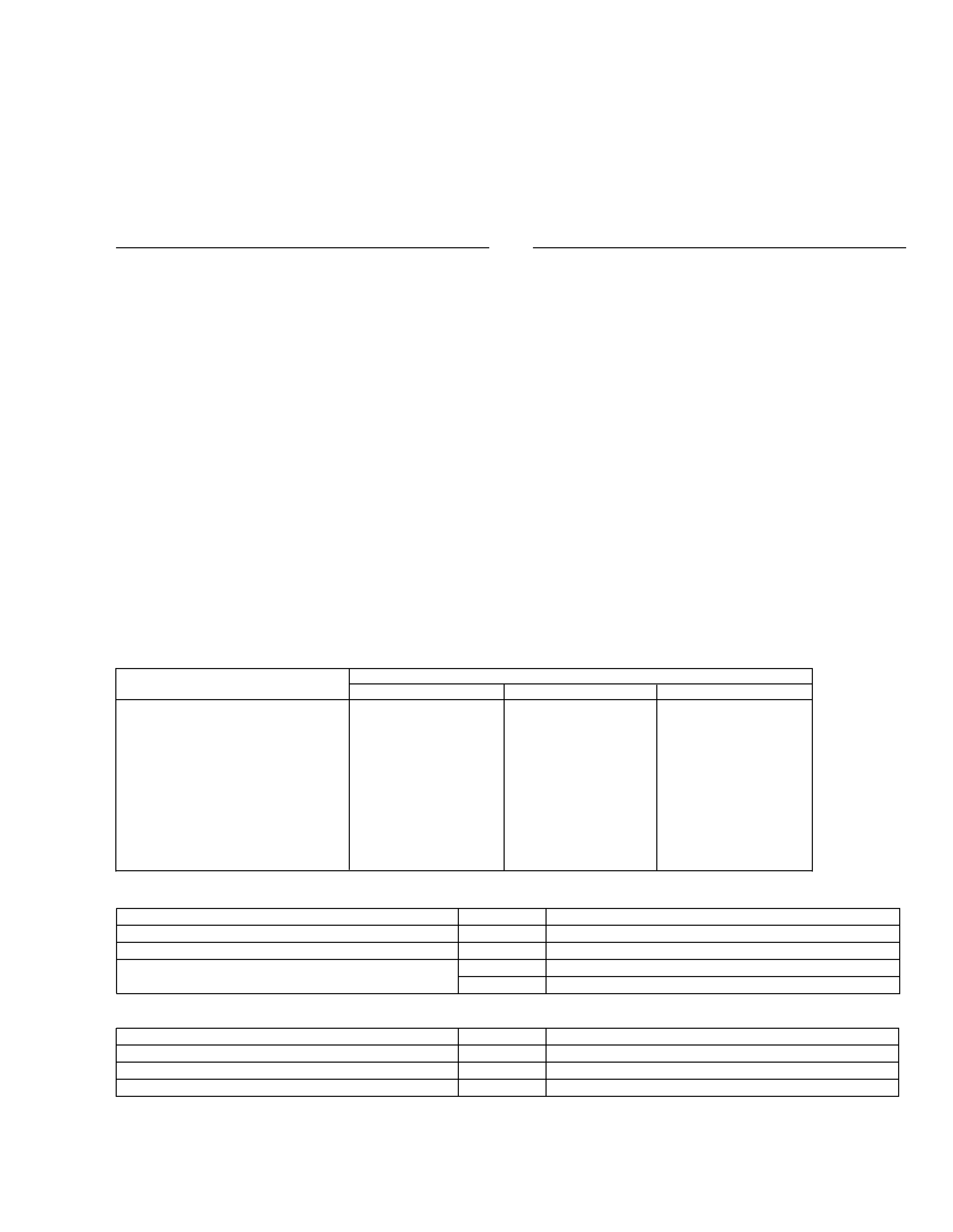
Part No.
Mark No. Symbol and Description DEH-P400/X1N/UC
DEH-P4000/X1N/UC
DEH-P4050/X1N/ES
12 Polyethylene Bag
CEG1173
CEG1173
CEG-162
14 Carton
CHG3642
CHG3641
CHG3643
15 Contain Box
CHL3642
CHL3641
CHL3643
20-1 Owner's Manual
CRD2822
CRD2820
CRD2832
20-2 Owner's Manual
Not used
Not used
CRD2833
20-3 Installation Manual
CRD2823
CRD2821
CRD2834
* 20-4 Warranty Card
CRY1070
Not used
Not used
* 20-6 Card
Not used
ARY1048
Not used
* 20-7 Label
CRW1343
CRW1343
Not used
(2) CONTRAST TABLE
DEH-P400/X1N/UC, DEH-P4000/X1N/UC and DEH-P4050/X1N/ES are constructed the same except for the
following:
4
DEH-P400,P4000,P4050
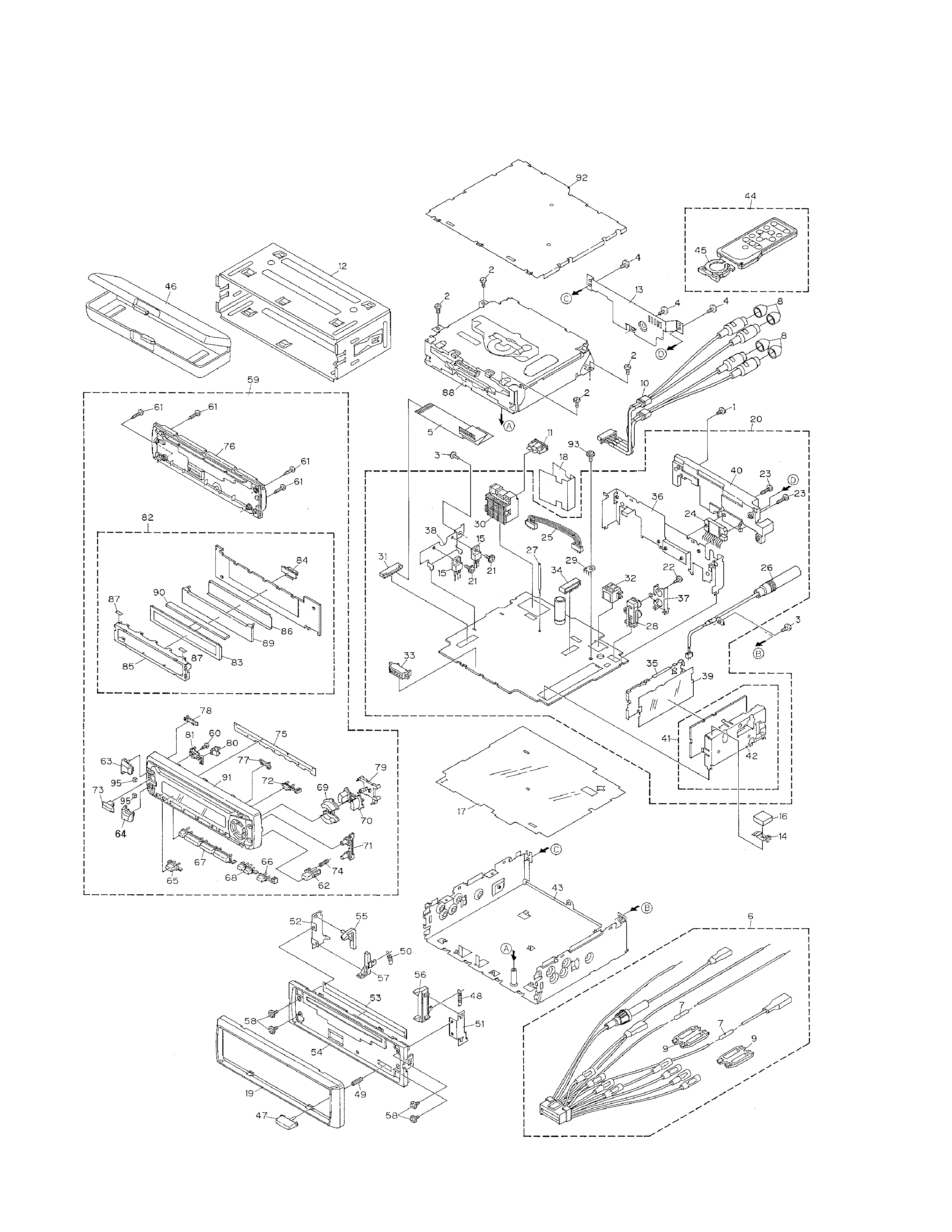
2.2 EXTERIOR
- DEH-P400/X1N/UC

5
DEH-P400,P4000,P4050
1 Screw
BMZ26P120FMC
2 Screw
BSZ26P060FMC
3 Screw
BSZ30P060FMC
4 Screw
BSZ30P120FMC
5 Cable
CDE6018
6 Cord Assy
CDE5769
7 Resistor
RS1/2PMF102J
8 Cap
CNV2680
9 Cap
CNS1472
10 Cord Assy
CDE5771
11 Fuse(10A)
CEK1136
12 Holder
CNC6798
13 Cover
CNC8367
14 Earth Plate
CNC8368
15 Transistor(Q981,991)
2SD2396
16 Spacer
CNM4913
17 Insulator
CNM6006
18 Insulator
CNM6224
19 Panel
CNS5137
20 Tuner Amp Unit
CWM6077
21 Screw
ASZ26P080FMC
22 Screw
BPZ26P080FMC
23 Screw
BSZ26P160FMC
24 IC(IC551)
PAL005A
25 Connector(CN551)
CDE5996
26 Antenna Cable(CN502)
CDH1254
27 Clamper
CEF1006
28 Pin Jack(CN431)
CKB1028
29 Terminal(CN501)
CKF1059
30 Connector(CN951)
CKM1299
*
31 Connector(CN681)
CKS2227
32 Connector(CN411)
CKS3408
33 Connector(CN651)
CKS3581
34 Connector(CN433)
CKS3602
35 Holder
CNC7533
36 Holder
CNC8037
37 Holder
CNC8041
38 Holder
CNC8043
39 Insulator
CNM5967
40 Heat Sink
CNR1506
41 FM/AM Tuner Unit
CWE1501
42 Holder
CNC7532
43 Chassis Unit
CXB3167
44 Remote Control Unit
CXB3455
45 Cover
CNS4948
46 Case Assy
CXB3520
47 Button
CAC4836
48 Spring
CBH1835
49 Spring
CBH1996
50 Spring
CBH2208
51 Bracket
CNC6791
52 Holder
CNC8042
53 Cover
CNM6276
54 Panel
CNS5189
55 Arm
CNV4692
56 Arm
CNV4728
57 Arm
CNV5576
58 Screw
IMS20P030FZK
59 Detach Grille Assy
CXB3600
60 Screw
BPZ20P060FMC
61 Screw
BPZ20P100FZK
62 Button(DETACH)
CAC5789
63 Button(+)
CAC5833
64 Button(-)
CAC5836
65 Button(SOURCE)
CAC5838
66 Button(BAND)
CAC5839
67 Button(1-6)
CAC5840
68 Button(PGM,CL)
CAC5841
69 Button(UP,DOWN)
CAC5845
70 Button(<,>)
CAC5848
71 Button(F,A)
CAC5851
72 Button(EJECT)
CAC5853
73 Button(EQ)
CAC6132
74 Spring
CBH2210
75 Cover
CNM6290
76 Cover
CNS5187
77 Lighting Conductor
CNV5567
78 Lighting Conductor
CNV5568
79 Housing
CNV5572
80 Housing
CNV5573
81 Housing
CNV5575
82 Keyboard Unit
CWM6094
83 LCD(LCD1801)
CAW1498
84 Connector(CN1801)
CKS3580
85 Holder
CNC8036
86 Sheet
CNM6004
87 Sheet
CNM6291
88 CD Mechanism Module
CXK5200
89 Lighting Conductor
CNV5569
90 Connector
CNV5571
91 Grille Unit
CXB3166
92 Case Unit
CXB4033
93 Screw
ISS26P055FUC
94 ·····
95 Cushion
CNM6373
- EXTERIOR SECTION PARTS LIST
Mark No. Description
Part No.
Mark No. Description
Part No.