PIONEER CORPORATION
4-1, Meguro 1-Chome, Meguro-ku, Tokyo 153-8654, Japan
PIONEER ELECTRONICS (USA) INC.
P.O.Box 1760, Long Beach, CA 90801-1760 U.S.A.
PIONEER EUROPE NV
Haven 1087 Keetberglaan 1, 9120 Melsele, Belgium
PIONEER ELECTRONICS ASIACENTRE PTE.LTD. 253 Alexandra Road, #04-01, Singapore 159936
C PIONEER CORPORATION 2003
K-ZZD. APR. 2003 Printed in Japan
ORDER NO.
CRT3062
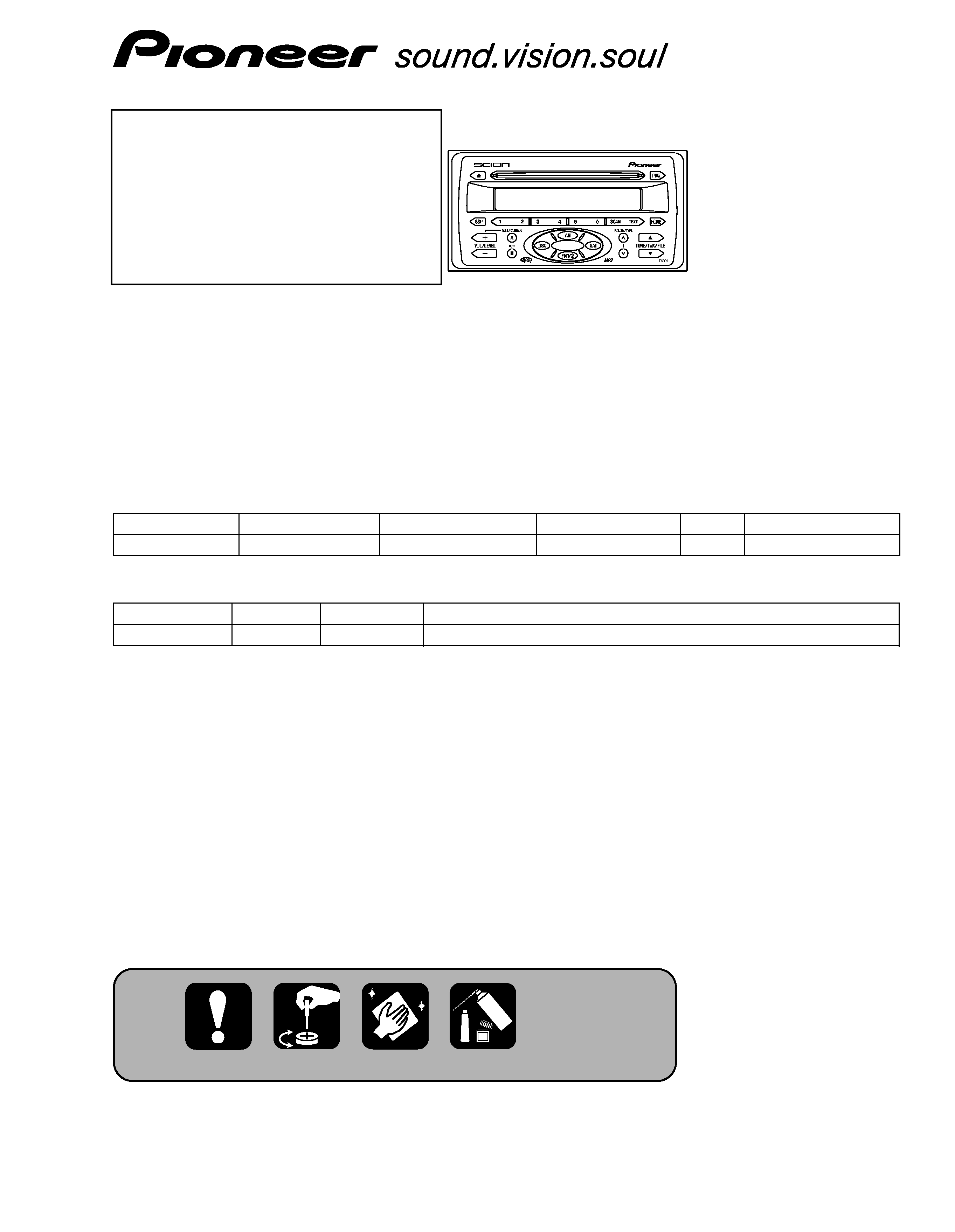
SCION AUDIO SYSTEM SINGLE CD DECK
DEH-M8037ZT
UC
Service
Manual
TOYOTA
DEH-M8037ZT/UC
For details, refer to "Important symbols for good services".
VEHICLE
DESTINATION
PRODUCED AFTER
TOYOTA PART No.
ID No.
PIONEER MODEL No.
xA, xB
U.S.A.
April 2003
86120-0W080
T1801
DEH-M8037ZT/UC
- This service manual should be used together with the following manual(s):
Model No.
Order No.
Mech. Module Remarks
CX-3057
CRT3026
S10MP3
CD Mech. Module:Circuit Description, Mech.Description, Disassembly
2
1
234
12
34
F
E
D
C
B
A
DEH-M8037ZT/UC
[ Important symbols for good services ]
In this manual, the symbols shown-below indicate that adjustments, settings or cleaning should be made securely.
When you find the procedures bearing any of the symbols, be sure to fulfill them:
2. Adjustments
To keep the original performances of the product, optimum adjustments or specification confirmation is indispensable.
In accordance with the procedures or instructions described in this manual, adjustments should be performed.
3. Cleaning
For optical pickups, tape-deck heads, lenses and mirrors used in projection monitors, and other parts requiring cleaning,
proper cleaning should be performed to restore their performances.
5. Lubricants, glues, and replacement parts
Appropriately applying grease or glue can maintain the product performances. But improper lubrication or applying
glue may lead to failures or troubles in the product. By following the instructions in this manual, be sure to apply the
prescribed grease or glue to proper portions by the appropriate amount.For replacement parts or tools, the prescribed
ones should be used.
4. Shipping mode and shipping screws
To protect the product from damages or failures that may be caused during transit, the shipping mode should be set or
the shipping screws should be installed before shipping out in accordance with this manual, if necessary.
1. Product safety
You should conform to the regulations governing the product (safety, radio and noise, and other regulations), and
should keep the safety during servicing by following the safety instructions described in this manual.
SAFETY INFORMATION
- CD Section Precaution
1. Before disassembling the unit, be sure to turn off
the power. Unplugging and plugging the connectors
during power-on mode may damage the ICs inside
the unit.
2. To protect the pickup unit from electrostatic discharge
during servicing, take an appropriate treatment
(shorting-solder) by referring to "the DISASSEMBLY"
on page 56.
3. After replacing the pickup unit, be sure to check the
grating. (See p.49.)
This service manual is intended for qualified service technicians; it is not meant for the casual do-it-yourselfer.
Qualified technicians have the necessary test equipment and tools, and have been trained to properly and safely repair
complex products such as those covered by this manual.
Improperly performed repairs can adversely affect the safety and reliability of the product and may void the warranty.
If you are not qualified to perform the repair of this product properly and safely; you should not risk trying to do so
and refer the repair to a qualified service technician.

3
5
6
7
8
F
E
D
C
B
A
5
6
7
8
DEH-M8037ZT/UC
CONTENTS
SAFETY INFORMATION ......................................................................................................................................................2
1. SPECIFICATIONS .................................................................................................................................................................4
2. EXPLODED VIEWS AND PARTS LIST ................................................................................................................................5
2.1 PACKING..........................................................................................................................................................................5
2.2 EXTERIOR ........................................................................................................................................................................6
2.3 CD MECHANISM MODULE ............................................................................................................................................8
3. BLOCK DIAGRAM AND SCHEMATIC DIAGRAM.............................................................................................................10
3.1 BLOCK DIAGRAM .........................................................................................................................................................10
3.2 OVERALL CONNECTION DIAGRAM(GUIDE PAGE) ...................................................................................................12
3.3 KEYBOARD UNIT ..........................................................................................................................................................18
3.4 CD MECHANISM MODULE(GUIDE PAGE)..................................................................................................................20
4. PCB CONNECTION DIAGRAM..........................................................................................................................................30
4.1 MAIN UNIT ....................................................................................................................................................................30
4.2 KEYBOARD UNIT ..........................................................................................................................................................34
4.3 CD MECHANISM MODULE ..........................................................................................................................................36
5. ELECTRICAL PARTS LIST..................................................................................................................................................38
6. ADJUSTMENT ...................................................................................................................................................................45
6.1 CONNECTION DIAGRAM .............................................................................................................................................45
6.2 TEST MODE...................................................................................................................................................................46
6.3 CD ADJUSTMENT ........................................................................................................................................................47
6.4 CHECKING THE GRATING AFTER CHANGING THE PICKUP UNIT...........................................................................49
6.5 ERROR MODE ...............................................................................................................................................................51
6.6 AVC-LAN DIAGNOSIS MODE.......................................................................................................................................52
7. GENERAL INFORMATION.................................................................................................................................................56
7.1 DIAGNOSIS ...................................................................................................................................................................56
7.1.1 DISASSEMBLY .......................................................................................................................................................56
7.1.2 CONNECTOR FUNCTION DESCRIPTION .............................................................................................................60
7.2 PARTS ............................................................................................................................................................................61
7.2.1 IC .............................................................................................................................................................................61
7.2.2 DISPLAY ..................................................................................................................................................................71
7.3 EXPLANATION ..............................................................................................................................................................72
7.3.1 SYSTEM BLOCK DIAGRAM ..................................................................................................................................72
7.3.2 OPERATIONAL FLOW CHART ...............................................................................................................................73
7.4 CLEANING .....................................................................................................................................................................74
8. OPERATIONS .....................................................................................................................................................................75

4
1
234
12
34
F
E
D
C
B
A
DEH-M8037ZT/UC
1. SPECIFICATIONS
General
Power source . . . . . . . . . . . . . 13.2 V DC
(10.5 16.0 V allowable)
Grounding system
. . . . . . Negative type
Max. current consumption
. . . . . . . 15 A
Backup current . . . . . . . . . 0.3 mA or less
Dimensions ( W
× H × D )
. . . . . . . . . . . . . . . . 200
× 100 × 165 mm
Weight . . . . . . . . . . . . . . . . . . . . . . 1.8 kg
Audio
Tone controls
(Bass) . . . . . . . . . . . . Frequency : 55 Hz
Level : +11 dB -13 dB
(Treble) . . . . . . . . Frequency : 14080 Hz
Level : +8 dB -10 dB
Maximum power output . . . . . . 40 W
× 4
Load impedance
. . . . . . . . . . . . . . . . 4
CD player
System . . . . Compact disc audio system
Usable discs
. . . . . . . . . . . Compact disc
Signal format
Sampling frequency . . . . . . . . 44.1 kHz
Number of quantization bits
. . . . . . . . . . . . . . . . . . . . . . . . 16; linear
Number of channels
. . . . . . . . 2 (stereo)
MP3 decoding format
. . . . . . . . . . . MPEG1 & 2 Audio Layer 3
AM tuner
Frequency range . . . . . . . 530 1710 kHz
FM tuner
Frequency range . . . . 87.75 107.9 MHz
5
5
6
7
8
F
E
D
C
B
A
5
6
7
8
DEH-M8037ZT/UC
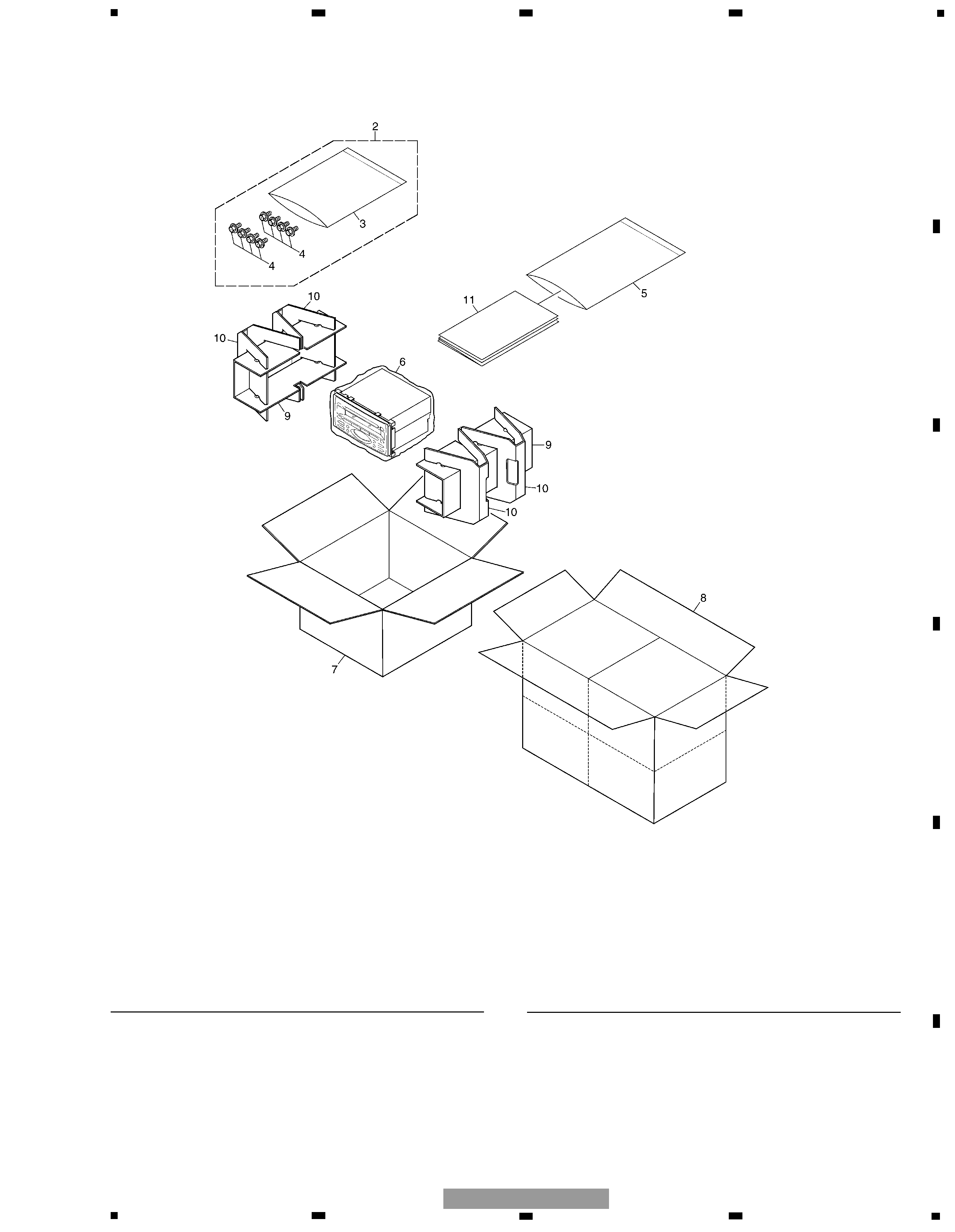
2. EXPLODED VIEWS AND PARTS LIST
2.1 PACKING
1 ·····
2 Screw Assy
CEA3954
*
3 Polyethylene Bag
CEG-127
4 Screw
HMF50P080FTC
*
5 Polyethylene Bag
CEG1116
*
6 Polyethylene Bag
CEG1322
7 Carton
CHA3274
8 Contain Box
CHL5058
9 Protector
CHP2140
10 Protector
CHP2141
11 Owner's Manual
CRB1826
(English)
Mark No. Description
Part No.
Mark No. Description
Part No.
NOTE:
- Parts marked by "*" are generally unavailable because they are not in our Master Spare Parts List.
- Screws adjacent to
mark on the product are used for disassembly.
- For the applying amount of lubricants or glue, follow the instructions in this manual.
( In the case of no amount instructions, apply as you think it appropriate.)
- PACKING SECTION PARTS LIST