PIONEER CORPORATION
4-1, Meguro 1-Chome, Meguro-ku, Tokyo 153-8654, Japan
PIONEER ELECTRONICS (USA) INC.
P.O.Box 1760, Long Beach, CA 90801-1760 U.S.A.
PIONEER EUROPE NV
Haven 1087 Keetberglaan 1, 9120 Melsele, Belgium
PIONEER ELECTRONICS ASIACENTRE PTE.LTD. 253 Alexandra Road, #04-01, Singapore 159936
C PIONEER CORPORATION 2002
K-ZZD. SEPT. 2002 Printed in Japan
ORDER NO.
CRT2934
AM/FM CD PLAYER WITH CD CHANGER CASSETTE TAPE PLAYER CONTROL
Service
Manual
HONDA
DEH-M6427ZH/ES
DEH-M6427ZH
ES
VEHICLE
DESTINATION
PRODUCED AFTER
HONDA PART No.
ID No.
PIONEER MODEL No.
City
Thailand
October 2002
08A50-SEL-700
23E70
DEH-M6427ZH/ES
For details, refer to "Important symbols for good services".
Model No.
Order No.
Mech. Module Remarks
CX-977
CRT2624
S9
CD Mech. Module:Circuit Description, Mech.Description, Disassembly
- This service manual should be used together with the following manual(s):
2
1
234
12
34
F
E
D
C
B
A
DEH-M6427ZH/ES
[ Important symbols for good services ]
In this manual, the symbols shown-below indicate that adjustments, settings or cleaning should be made securely.
When you find the procedures bearing any of the symbols, be sure to fulfill them:
2. Adjustments
To keep the original performances of the product, optimum adjustments or specification confirmation is indispensable.
In accordance with the procedures or instructions described in this manual, adjustments should be performed.
3. Cleaning
For optical pickups, tape-deck heads, lenses and mirrors used in projection monitors, and other parts requiring cleaning,
proper cleaning should be performed to restore their performances.
5. Lubricants, glues, and replacement parts
Appropriately applying grease or glue can maintain the product performances. But improper lubrication or applying
glue may lead to failures or troubles in the product. By following the instructions in this manual, be sure to apply the
prescribed grease or glue to proper portions by the appropriate amount.For replacement parts or tools, the prescribed
ones should be used.
4. Shipping mode and shipping screws
To protect the product from damages or failures that may be caused during transit, the shipping mode should be set or
the shipping screws should be installed before shipping out in accordance with this manual, if necessary.
1. Product safety
You should conform to the regulations governing the product (safety, radio and noise, and other regulations), and
should keep the safety during servicing by following the safety instructions described in this manual.
- CD section precaution
1. Before disassembling the unit, be sure to turn off the
power. Unplugging and plugging the connectors dur-
ing power-on mode may damage the ICs inside the
unit.
2. To protect the pickup unit from electrostatic dis-
charge during servicing, take an appropriate treat-
ment (shorting-solder) by referring to "the DISAS-
SEMBLY" on page 45.
3. After replacing the pickup unit, be sure to check the
grating. (See p.38.)
SAFETY INFORMATION
This service manual is intended for qualified service technicians; it is not meant for the casual do-it-yourselfer.
Qualified technicians have the necessary test equipment and tools, and have been trained to properly and safely repair
complex products such as those covered by this manual.
Improperly performed repairs can adversely affect the safety and reliability of the product and may void the warranty.
If you are not qualified to perform the repair of this product properly and safely, you should not risk trying to do so
and refer the repair to a qualified service technician.

3
5
6
7
8
F
E
D
C
B
A
5
6
7
8
DEH-M6427ZH/ES
CONTENTS
SAFETY INFORMATION ............................................2
1. SPECIFICATIONS........................................................3
2. EXPLODED VIEWS AND PARTS LIST .......................4
3. BLOCK DIAGRAM AND SCHEMATIC DIAGRAM ...10
4. PCB CONNECTION DIAGRAM ................................22
5. ELECTRICAL PARTS LIST ........................................30
6. ADJUSTMENT..........................................................36
7. GENERAL INFORMATION .......................................45
7.1 DIAGNOSIS ........................................................45
7.1.1 DISASSEMBLY .........................................45
7.1.2 CONNECTOR FUNCTION DESCRIPTION .......48
7.2 PARTS .................................................................49
7.2.1 IC................................................................49
7.2.2 DISPLAY ....................................................55
7.3 OPERATIONAL FLOW CHART ...........................56
7.4 CLEANING ..........................................................57
8. OPERATIONS............................................................58
1. SPECIFICATIONS
General
Power source ............... 13.2 V DC (10.8 -- 16.0 V allowable)
Grounding system ........................................... Negative type
Max. current consumption
..................... +B 15 A or less (When no slave is connected)
ACC 1 A or less (When no slave is connected)
Backup current .....................................................5 mA or less
Dimensions (chassis) ............ 180 (W)
× 52 (H) × 160 (D) mm
(nose) ............... 190 (W)
× 60 (H ) × 11.4 (D) mm
Weight ............................................................................ 1.3 kg
Amplifier
Maximum output power................................... 15 W or more
(4
, 1kHz, 10% T.H.D.)
Load impedance .............................. 4
(4 -- 8 allowable)
CD player
System ....................................... Compact disc audio system
Usable discs ...................................................... Compact disc
Signal format ......................... Sampling frequency: 44.1 kHz
Number of quantization bits: 16; linear
Signal-to-noise ratio ........................................ 60dB or more
Distortion ........................................................... 0.2% or more
FM tuner
Frequency range .......................................... 87.5 -- 108 MHz
Signal-to-noise ratio ........................................ 51dB or more
Distortion ............................................................. 1.3% or less
IF interference .................................................. 91 dB or more
Image interference .......................................... 41 dB or more
Stereo separation ............................... 26 dB or more (1 kHz)
AM tuner
Frequency range .......................................... 531 -- 1,602 kHz
S/N 20dB usable sensitivity ............................. 27 dBµ ± 5 dB
Signal-to-noise ratio ........................................ 46dB or more
Distortion ............................................................. 0.9% or less
IF interference .................................................. 61 dB or more
Image interference .......................................... 51 dB or more
Note:
Specifications and the design are subject to possible modifica-
tion without notice due to improvements.
4
1
234
12
34
F
E
D
C
B
A
DEH-M6427ZH/ES
4
7
5
2
1
8
6
3
3
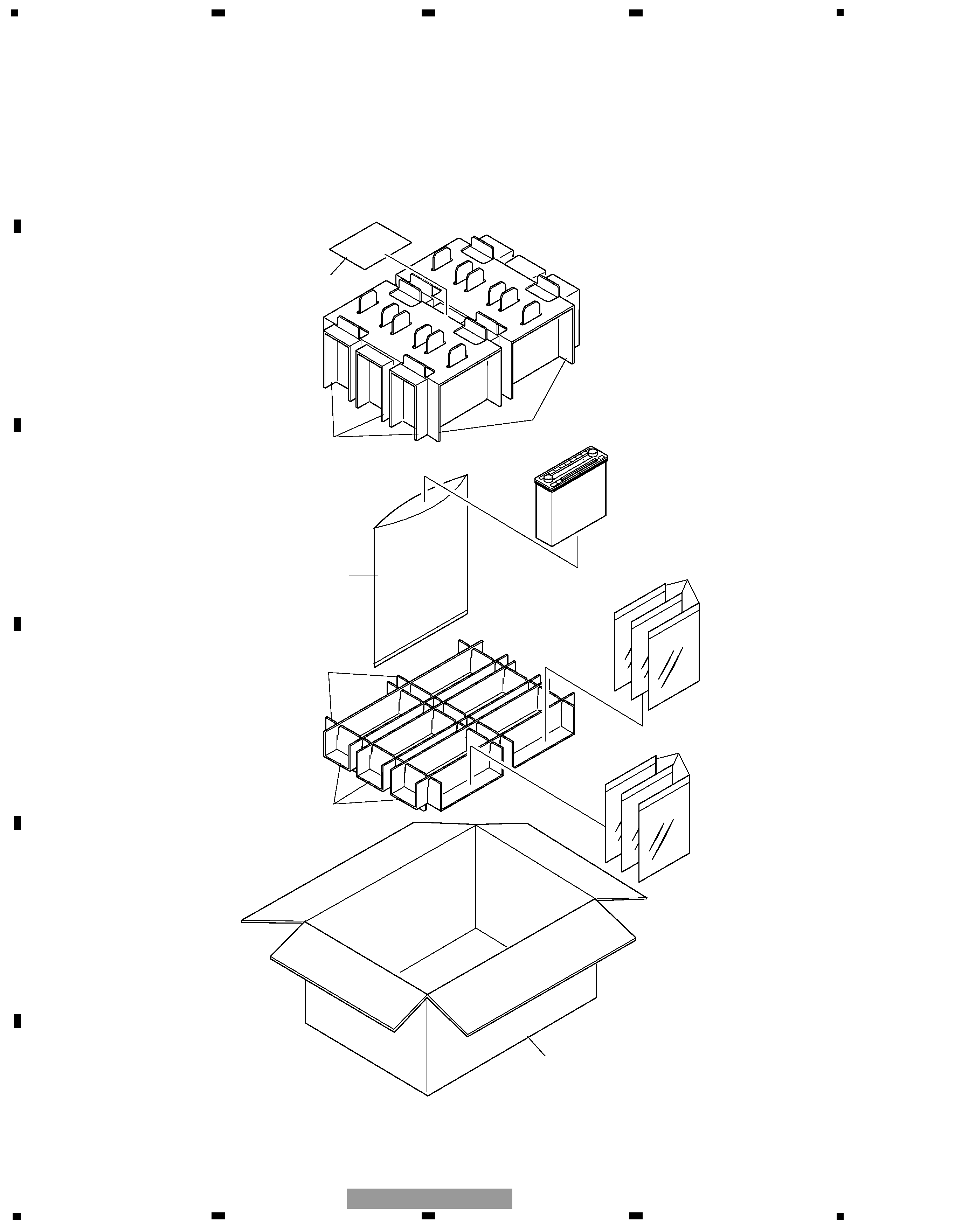
2. EXPLODED VIEWS AND PARTS LIST
2.1 PACKING
5
5
6
7
8
F
E
D
C
B
A
5
6
7
8
DEH-M6427ZH/ES
1 Protector
CHP2644
2 Protector
CHP2646
3-1 Polyethylene Bag
CEG1116
3-2 Owner's Manual
CRB1814
3-3 Owner's Manual
CRB1815
4 Polyethylene Bag
CEG1042
5 Contain Box
CHL4868
6 Protector
CHP2643
7 Protector
CHP2645
*
8 Card
CRL2360
Mark No. Description
Part No.
- PACKING SECTION PARTS LIST
NOTE:
- Parts marked by "*" are generally unavailable because they are not in our Master Spare Parts List.
- Screws adjacent to
mark on the product are used for disassembly.
- For the applying amount of lubricants or glue, follow the instructions in this manual.
( In the case of no amount instructions, apply as you think it appropriate.)
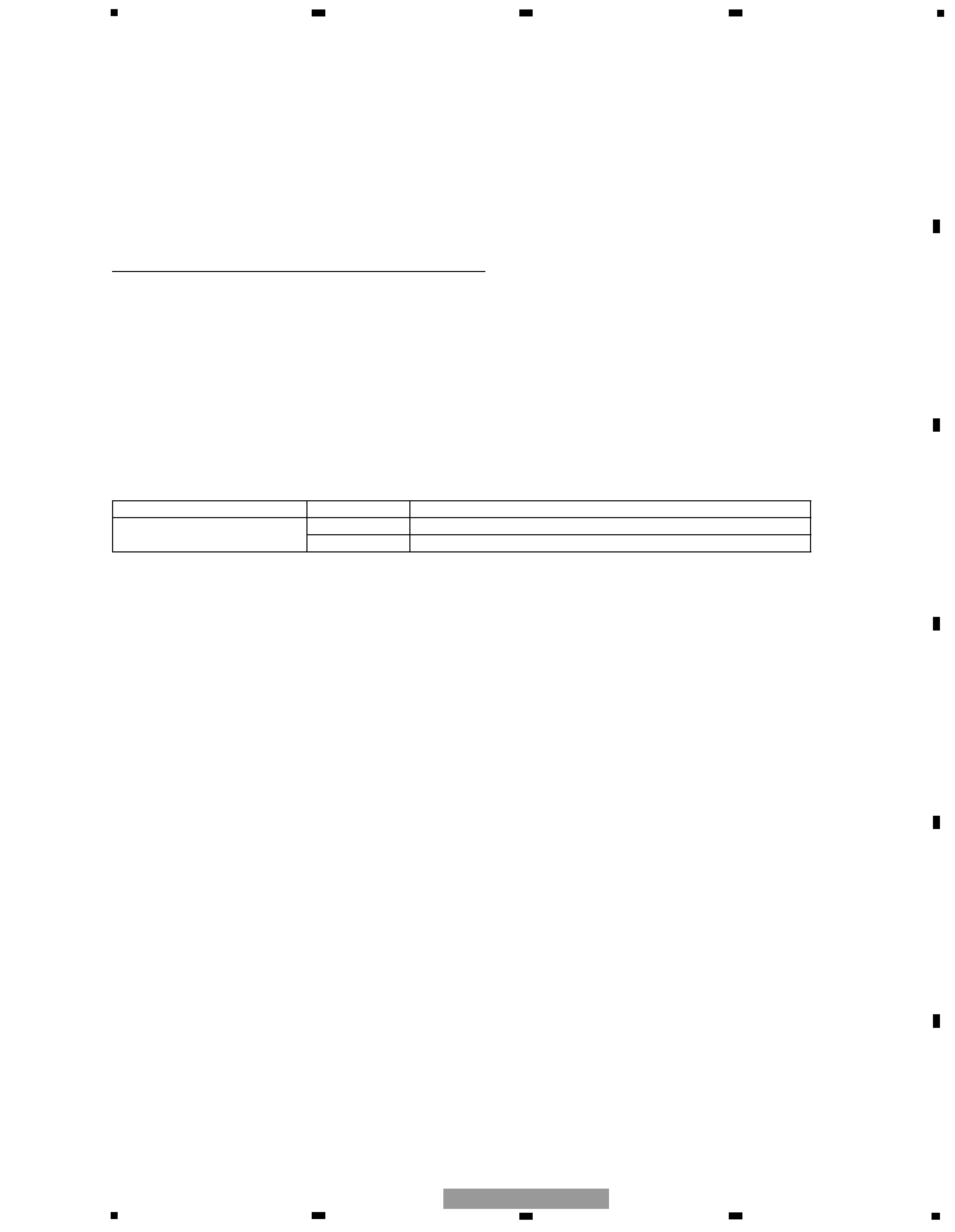
- Owner's Manual, Installation Manual
Model
Part No.
Language
DEH-M6427ZH/ES
CRB1814
English
CRB1815
Thai