PIONEER CORPORATION
4-1, Meguro 1-Chome, Meguro-ku, Tokyo 153-8654, Japan
PIONEER ELECTRONICS (USA) INC.
P.O.Box 1760, Long Beach, CA 90801-1760 U.S.A.
PIONEER EUROPE NV
Haven 1087 Keetberglaan 1, 9120 Melsele, Belgium
PIONEER ELECTRONICS ASIACENTRE PTE.LTD. 253 Alexandra Road, #04-01, Singapore 159936
C PIONEER CORPORATION 2001
K-ZZD. NOV. 2001 Printed in Japan
ORDER NO.
CRT2760
HIGH POWER CD PLAYER WITH RDS TUNER
DEH-3400R
XN/EW
Service
Manual
DEH-3400R/XN/EW
CONTENTS
1. SAFETY INFORMATION ............................................3
2. EXPLODED VIEWS AND PARTS LIST .......................4
3. BLOCK DIAGRAM AND SCHEMATIC DIAGRAM ...12
4. PCB CONNECTION DIAGRAM ................................32
5. ELECTRICAL PARTS LIST ........................................40
6. ADJUSTMENT..........................................................48
7. GENERAL INFORMATION .......................................52
7.1 DIAGNOSIS ........................................................52
7.1.1 DISASSEMBLY .........................................52
7.1.2 CONNECTOR FUNCTION DESCRIPTION .......55
7.2 PARTS .................................................................56
7.2.1 IC................................................................56
7.2.2 DISPLAY ....................................................65
7.3 OPERATIONAL FLOW CHART ...........................66
7.4 CLEANING ..........................................................67
8. OPERATIONS AND SPECIFICATIONS.....................68
- This service manual should be used together with the following manual(s):
Model No.
Order No.
Mech. Module Remarks
CX-977
CRT2624
S9
CD Mech. Module:Circuit Description, Mech.Description, Disassembly
DEH-2460R XN/EW
DEH-2430R XN/EW
For details, refer to "Important symbols for good services" on the next page.
2
DEH-3400R,2460R,2430R
- CD Player Service Precautions
1. For pickup unit(CXX1480) handling, please refer
to"Disassembly"(see page 52).
During replacement, handling precautions shall be
taken to prevent an electrostatic discharge(protection
by a jumper-solder).
2. During disassembly, be sure to turn the power off
since an internal IC might be destroyed when a con-
nector is plugged or unplugged.
3. Please checking the grating after changing the pickup
unit(see page 49).
4. In this product, because the memory capacity of the
microcomputer is insufficient, the test mode is not
installed. However grating of the pickup unit can be
confirmed.
[ Important symbols for good services ]
In this manual, the symbols shown-below indicate that adjustments, settings or cleaning should be made securely.
When you find the procedures bearing any of the symbols, be sure to fulfill them:
2. Adjustments
To keep the original performances of the product, optimum adjustments or specification confirmation is indispensable.
In accordance with the procedures or instructions described in this manual, adjustments should be performed.
3. Cleaning
For optical pickups, tape-deck heads, lenses and mirrors used in projection monitors, and other parts requiring cleaning,
proper cleaning should be performed to restore their performances.
5. Lubricants, glues, and replacement parts
Appropriately applying grease or glue can maintain the product performances. But improper lubrication or applying
glue may lead to failures or troubles in the product. By following the instructions in this manual, be sure to apply the
prescribed grease or glue to proper portions by the appropriate amount.For replacement parts or tools, the prescribed
ones should be used.
4. Shipping mode and shipping screws
To protect the product from damages or failures that may be caused during transit, the shipping mode should be set or
the shipping screws should be installed before shipping out in accordance with this manual, if necessary.
1. Product safety
You should conform to the regulations governing the product (safety, radio and noise, and other regulations), and
should keep the safety during servicing by following the safety instructions described in this manual.
3
DEH-3400R,2460R,2430R
1. SAFETY INFORMATION
This service manual is intended for qualified service technicians; it is not meant for the casual do-it-yourselfer.
Qualified technicians have the necessary test equipment and tools, and have been trained to properly and safely repair
complex products such as those covered by this manual.
Improperly performed repairs can adversely affect the safety and reliability of the product and may void the warranty.
If you are not qualified to perform the repair of this product properly and safely, you should not risk trying to do so
and refer the repair to a qualified service technician.
1. Safety Precautions for those who Service this Unit.
· When checking or adjusting the emitting power of the laser diode exercise caution in order to get safe, reliable
results.
Caution:
1. During repair or tests, minimum distance of 13cm from the focus lens must be kept.
2. During repair or tests, do not view laser beam for 10 seconds or longer.
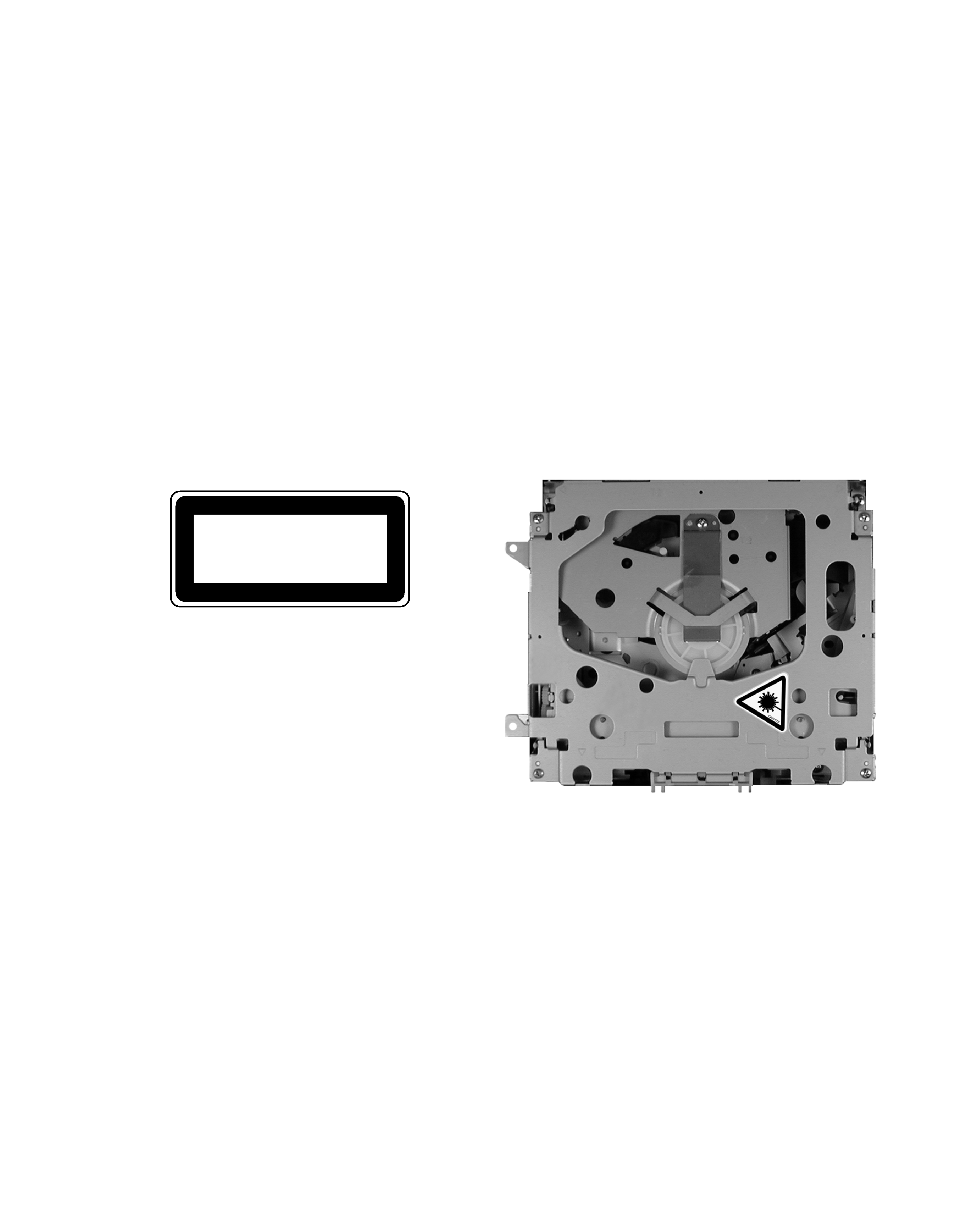
2. A "CLASS 1 LASER PRODUCT" label is affixed to the
bottom of the player.
3. The triangular label is attached to the mechanism
unit frame.
4. Specifications of Laser Diode
Specifications of laser radiation fields to which human access is possible during service.
Wavelength
=
800 nanometers
CLASS 1
LASER PRODUCT
4
DEH-3400R,2460R,2430R
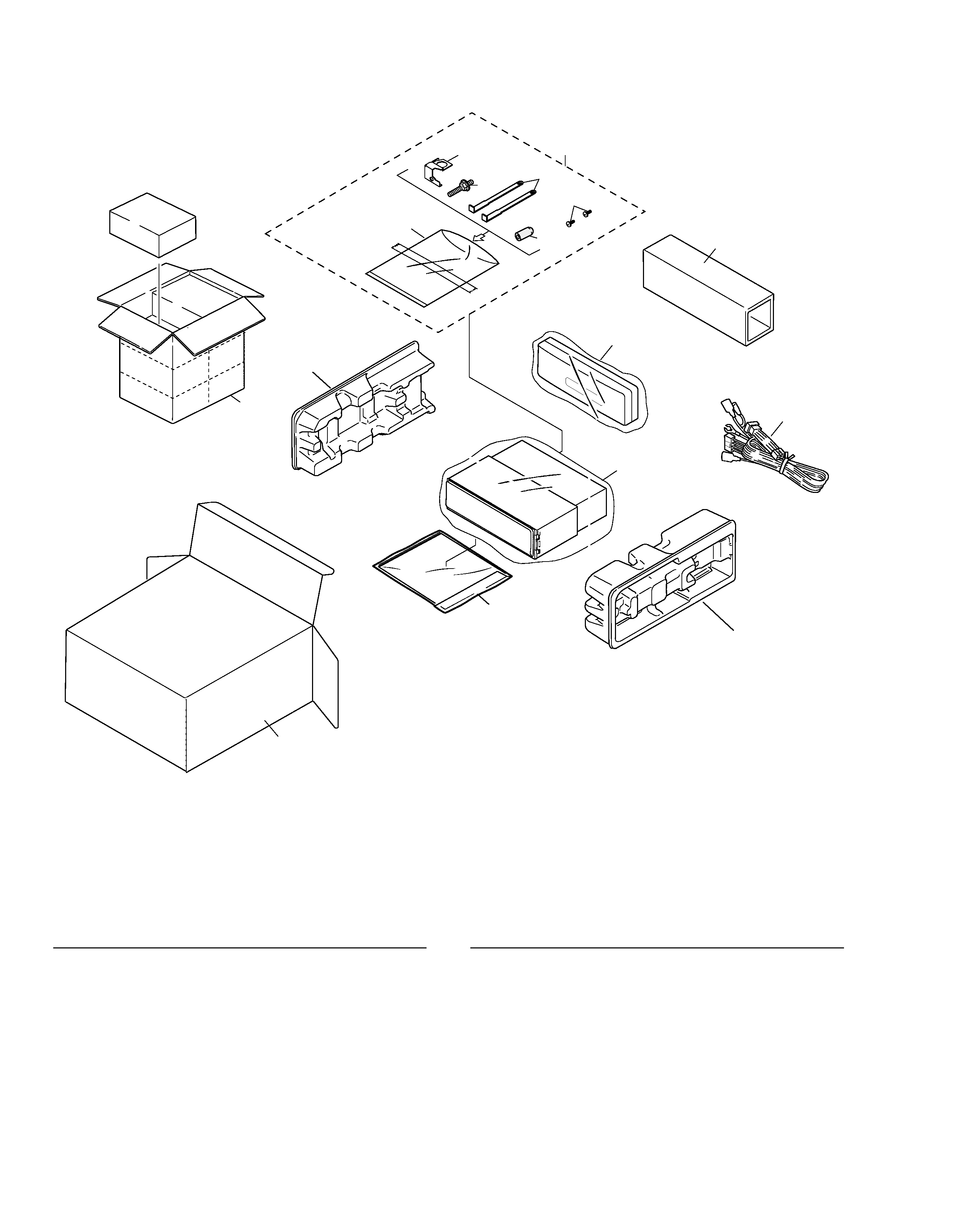
1 Cord Assy
CDE6467
2 Inner Box
See Contrast table(2)
3 Accessory Assy
CEA3062
4 Screw
CBA1002
5 Handle
CNC5395
6 Bush
CNV3930
*
7 Polyethylene Bag
E36-615
8 Polyethylene Bag
CEG-162
9 Carton
See Contrast table(2)
10 Contain Box
See Contrast table(2)
11 Protector
CHP2251
12 Protector
CHP2252
13-1 Polyethylene Bag
CEG1116
13-2 Owner's Manual
CRD3495
13-3 Installation Manual
CRD3500
* 13-4 Passport
CRY1013
* 13-5 Warranty Card
CRY1157
14 Case Assy
CXB3520
15 Earth Plate
CNC9450
16 Screw
BPZ20P060FZK
Mark No. Description
Part No.
Mark No. Description
Part No.
(1) PACKING SECTION PARTS LIST
2. EXPLODED VIEWS AND PARTS LIST
2.1 PACKING
13
14
10
8
11
12
9
1
2
6
5
7
4
3
15
16
NOTE:
- Parts marked by "*" are generally unavailable because they are not in our Master Spare Parts List.
- Screws adjacent to
mark on the product are used for disassembly.
- For the applying amount of lubricants or glue, follow the instructions in this manual.
( In the case of no amount instructions, apply as you think it appropriate.)
5
DEH-3400R,2460R,2430R
Part No.
Mark No. Symbol and Description DEH-3400R/XN/EW
DEH-2460R/XN/EW
DEH-2430R/XN/EW
2 Inner Box
CHW1754
Not used
Not used
9 Carton
CHG4546
CHG4642
CHG4647
10 Contain Box
CHL4546
CHL4642
CHL4647
(2) CONTRAST TABLE
DEH-3400R/XN/EW, DEH-2460R/XN/EW and DEH-2430R/XN/EW are constructed the same except for the
following:
- Owner's Manual, Installation Manual
Model
Part No.
Language
DEH-3400R/XN/EW
CRD3495
English, Spanish, German, French, Italian, Dutch
DEH-2460R/XN/EW
CRD3500
DEH-2430R/XN/EW