ORDER NO.
PIONEER CORPORATION 4-1, Meguro 1-chome, Meguro-ku, Tokyo 153-8654, Japan
PIONEER ELECTRONICS (USA) INC. P.O. Box 1760, Long Beach, CA 90801-1760, U.S.A.
PIONEER EUROPE NV Haven 1087, Keetberglaan 1, 9120 Melsele, Belgium
PIONEER ELECTRONICS ASIACENTRE PTE. LTD. 253 Alexandra Road, #04-01, Singapore 159936
PIONEER CORPORATION 2003
DEH-1630R/XU/EW
CRT3174
HIGH POWER CD PLAYER WITH RDS TUNER
DEH-1630R
XU/EW
DEH-1600R XU/EW
DEH-1600RB XU/EW
This service manual should be used together with the following manual(s):
Model No.
Order No.
Mech.Module
Remarks
CX-3110
CRT3178
S10.1
CD Mech. Module : Circuit Description, Mech. Description, Disassembly
For details, refer to "Important symbols for good services".
K-ZZA. OCT. 2003 printed in Japan
DEH-1630R/XU/EW
2
1234
123
4
C
D
F
A
B
E
SAFETY INFORMATION
This service manual is intended for qualified service technicians; it is not meant for the casual do-it-yourselfer.
Qualified technicians have the necessary test equipment and tools, and have been trained to properly and safely
repair complex products such as those covered by this manual.
Improperly performed repairs can adversely affect the safety and reliability of the product and may void the warranty.
If you are not qualified to perform the repair of this product properly and safely, you should not risk trying to do so
and refer the repair to a qualified service technician.
1. Safety Precautions for those who Service this Unit.
· When checking or adjusting the emitting power of the laser diode exercise caution in order to get safe, reliable
results.
Caution:
1. During repair or tests, minimum distance of 13cm from the focus lens must be kept.
2. During repair or tests, do not view laser beam for 10 seconds or longer.
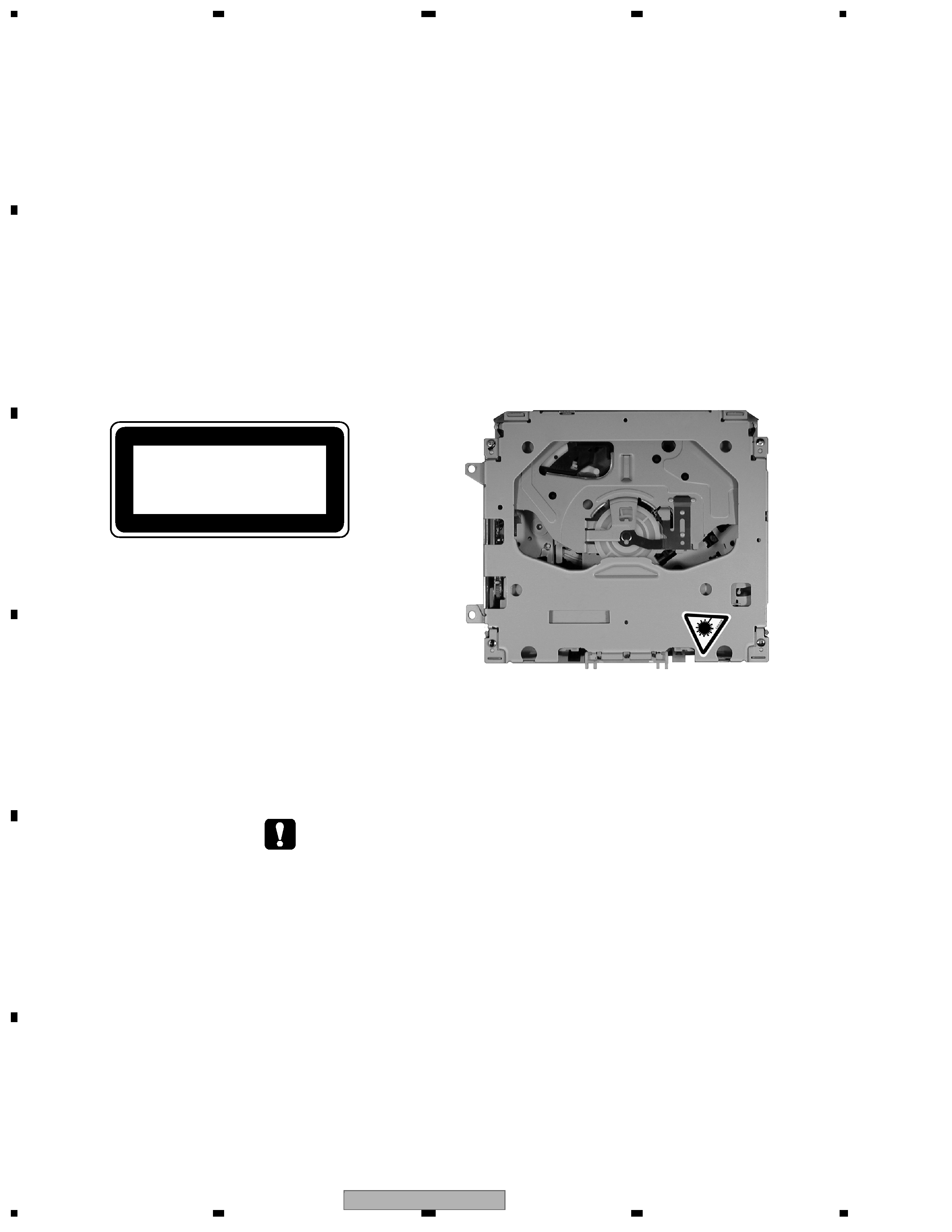
2. A "CLASS 1 LASER PRODUCT" label is affixed to the
bottom of the player.
3. The triangular label is attached to the mechanism
unit frame.
4. Specifications of Laser Diode
Specifications of laser radiation fields to which human access is possible during service.
Wavelength = 800 nanometers
CLASS 1
LASER PRODUCT
- CD Section Precaution
1. Before disassembling the unit, be sure to turn off
the power. Unplugging and plugging the connectors
during power-on mode may damage the ICs inside
the unit.
2. To protect the pickup unit from electrostatic discharge
during servicing, take an appropriate treatment
(shorting-solder) by referring to "the DISASSEMBLY"
on page 44.
3. After replacing the pickup unit, be sure to check the
grating. (See p.41.)
4. In this product, because the memory capacity of the
microcomputer is insufficient, the test mode is not
installed. However grating of the pickup unit can be
confirmed.
DEH-1630R/XU/EW
3
5
678
56
7
8
C
D
F
A
B
E
[ Important symbols for good services ]
In this manual, the symbols shown-below indicate that adjustments, settings or cleaning should be made securely.
When you find the procedures bearing any of the symbols, be sure to fulfill them:
2. Adjustments
To keep the original performances of the product, optimum adjustments or specification confirmation is indispensable.
In accordance with the procedures or instructions described in this manual, adjustments should be performed.
3. Cleaning
For optical pickups, tape-deck heads, lenses and mirrors used in projection monitors, and other parts requiring cleaning,
proper cleaning should be performed to restore their performances.
5. Lubricants, glues, and replacement parts
Appropriately applying grease or glue can maintain the product performances. But improper lubrication or applying
glue may lead to failures or troubles in the product. By following the instructions in this manual, be sure to apply the
prescribed grease or glue to proper portions by the appropriate amount.For replacement parts or tools, the prescribed
ones should be used.
4. Shipping mode and shipping screws
To protect the product from damages or failures that may be caused during transit, the shipping mode should be set or
the shipping screws should be installed before shipping out in accordance with this manual, if necessary.
1. Product safety
You should conform to the regulations governing the product (safety, radio and noise, and other regulations), and
should keep the safety during servicing by following the safety instructions described in this manual.

DEH-1630R/XU/EW
4
1234
123
4
C
D
F
A
B
E
CONTENTS
SAFETY INFORMATION ..................................................................................................................................... 2
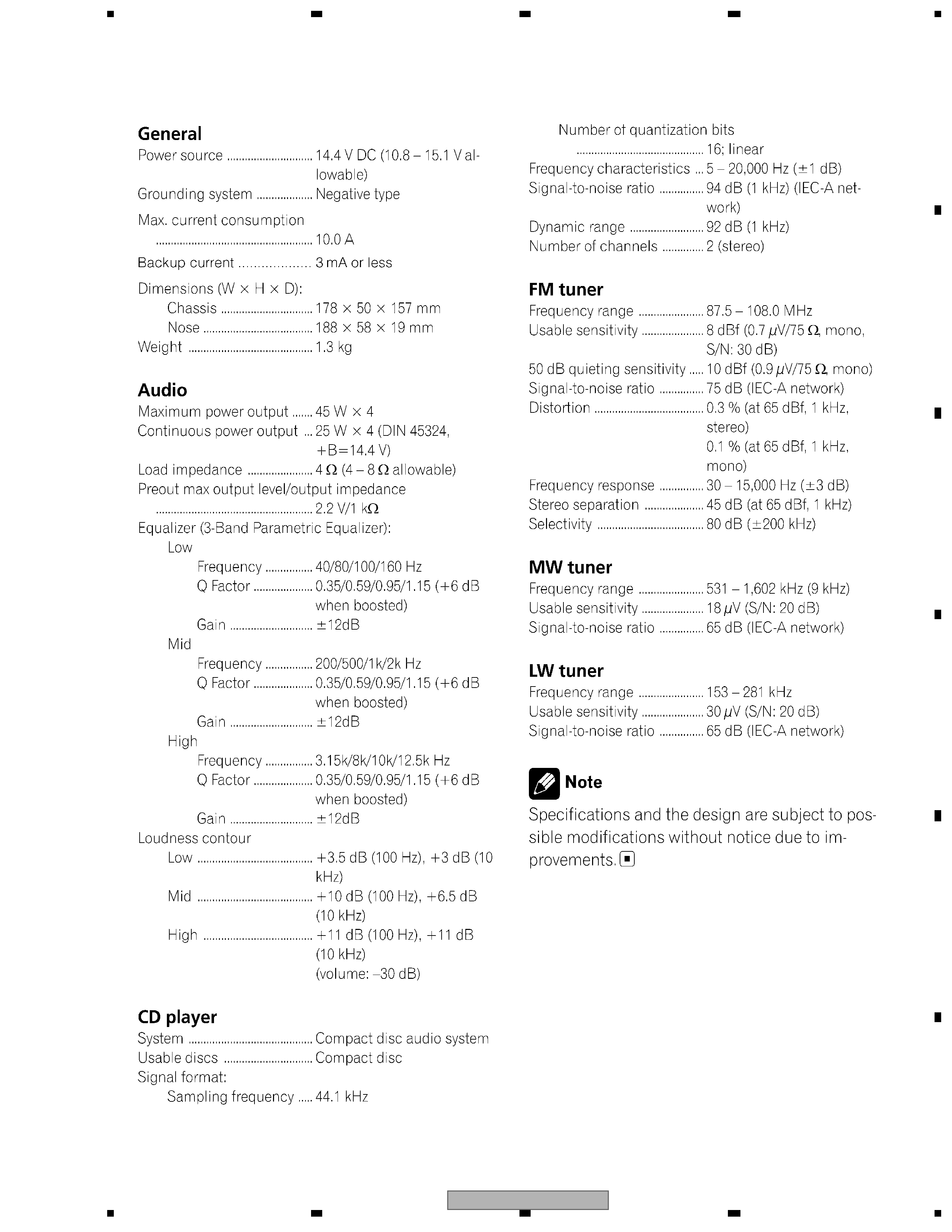
1. SPECIFICATIONS ............................................................................................................................................ 5
2. EXPLODED VIEWS AND PARTS LIST ............................................................................................................ 6
2.1 PACKING ................................................................................................................................................... 6
2.2 EXTERIOR................................................................................................................................................. 8
2.3 CD MECHANISM MODULE..................................................................................................................... 12
3. BLOCK DIAGRAM AND SCHEMATIC DIAGRAM ..........................................................................................14
3.1 BLOCK DIAGRAM ................................................................................................................................... 14
3.2 OVERALL CONNECTION DIAGRAM(GUIDE PAGE).............................................................................. 16
3.3 KEYBOARD UNIT.................................................................................................................................... 22
3.4 CD MECHANISM MODULE..................................................................................................................... 24
4. PCB CONNECTION DIAGRAM ..................................................................................................................... 28
4.1 TUNER AMP UNIT................................................................................................................................... 28
4.2 KEYBOARD UNIT.................................................................................................................................... 32
4.3 CD MECHANISM MODULE..................................................................................................................... 34
5. ELECTRICAL PARTS LIST ............................................................................................................................ 36
6. ADJUSTMENT ............................................................................................................................................... 40
6.1 CD ADJUSTMENT................................................................................................................................... 40
6.2 CHECKING THE GRATING AFTER CHANGING THE PICKUP UNIT .................................................... 41
6.3 ERROR MODE ........................................................................................................................................ 43
7. GENERAL INFORMATION ............................................................................................................................. 44
7.1 DIAGNOSIS ............................................................................................................................................. 44
7.1.1 DISASSEMBLY ..................................................................................................................................... 44
7.1.2 CONNECTOR FUNCTION DESCRIPTION .......................................................................................... 48
7.2 PARTS...................................................................................................................................................... 49
7.2.1 IC .......................................................................................................................................................... 49
7.2.2 DISPLAY ............................................................................................................................................... 56
7.3 OPERATIONAL FLOW CHART ............................................................................................................... 58
7.4 CLEANING............................................................................................................................................... 59
8. OPERATIONS ................................................................................................................................................ 60
DEH-1630R/XU/EW
5
5
678
56
7
8
C
D
F
A
B
E
1. SPECIFICATIONS