
Instruction book
DIGITAL TERRESTRIAL RECEIVER
DBR-T200GB
2
<BRB1056>
Welcome to digital terrestrial television!
The simplest way to get digital television is here. No dish. No cable.
Simply an aerial. It is, without doubt, the most exciting development in television history since the
first-ever broadcast in 1936.
In the last 60 years, there have been up to five normal channels on analogue television. Digital
terrestrial changes that.
ONdigital is the next step in television. Simply plug in your ONdigital box for a feast of mouth-
watering television. ONdigital is the only company that lets you pick and choose the channels you
want to watch.
Subscription channels from ONdigital, together with free channels from the BBC and ITV, cover
everthing from sports and movies to news and current affairs, all with improved picture and sound
... and widescreen too. No need for dishes. No need for cables. Simply ONdigital.
Before using this product, carefully read the "Safety Precautions" and this manual to ensure that
you can properly operate this product.
Keep this manual in a safe and convenient place where it can be easily referenced in the future.
"This equipment has been approved in accordance with Council Decision 98/482/EC for pan-
European single-terminal connection to the public switched-telephone network (PSTN). This
approval, however, does not unconditionally guarantee successful operation with every PSTN
network terminal due to differences between the PSTNs of the various countries. Should a
problem occur, contact the dealer where you purchased this equipment."
IMPORTANT
The lightning flash with arrowhead symbol,
within an equilateral triangle, is intended to
alert the user to the presence of uninsulated
"dangerous voltage" within the product's
enclosure that may be of sufficient magnitude
to constitute a risk of electric shock to persons.
CAUTION:
TO PREVENT THE RISK OF ELECTRIC SHOCK,
DO NOT REMOVE COVER (OR BACK).
NO
USER-SERVICEABLE PARTS INSIDE. REFER
SERVICING TO QUALIFIED SERVICE PERSON-
NEL.
The exclamation point within an equilateral
triangle is intended to alert the user to the
presence of important operating and
maintenance (servicing) instructions in the
literature accompanying the appliance.
RISK OF ELECTRIC SHOCK
DO NOT OPEN
CAUTION
WARNING: TO PREVENT FIRE OR SHOCK HAZARD, DO NOT EXPOSE THIS APPLIANCE TO
RAIN OR MOISTURE.
SAFETY PRECAUTIONS
FOR USE IN THE UNITED
KINGDOM
The wires in this mains lead are coloured in
accordance with the following code :
Blue
: Neutral
Brown
: Live
If the plug provided is unsuitable for your
socket outlets, the plug must be cut off and a
suitable plug fitted.
IMPORTANT
The cut-off plug should be disposed of and
must not be inserted into any 13 amp socket
as this can result in electric shock. The plug or
adaptor or the distribution panel should be
provided with 5 amp fuse. As the colours of
the wires in the mains lead of this appliance
may not correspond with coloured markings
identifying the terminals in your plug, proceed
as follows:
The wire which is coloured blue must be
connected to the terminal which is marked
with the letter N or coloured black. The wire
which is coloured brown must be connected
to the terminal which is marked with the letter
L or coloured red.
Do not connect either wire to the earth terminal
of a three pin plug.
NOTE
After replacing or changing a fuse, the fuse
cover in the plug must be replaced with a fuse
cover which corresponds to the colour of the
insert in the base of the plug or the word that
is embossed on the base of the plug, and the
appliance must not be used without a fuse
cover. If lost replacement fuse covers can be
obtained from: your dealer.
Only 5 A fuses approved by B.S.I. or A.S.T.A
to B.S. 1362 should be used.

3
<BRB1056>
SAFETY PRECAUTIONS ................................. 2
BEFORE USING YOUR RECEIVER
INCLUDED ACCESSORIES ....................... 4
OPERATION PANEL FEATURES AND
FUNCTIONS ................................... 5
Front and Back Panels ........................ 5
Remote Control Unit ........................... 7
Putting Batteries
in the Remote Controller ............. 10
Remote Controller
Operation Range ......................... 10
CONNECTIONS
BASIC CONNECTIONS ............................ 11
Television and VCR with
SCART Sockets ............................. 11
Television and VCR with Only Standard
Coaxial Antenna Input ........................ 13
Connecting to a Stereo ..................... 15
Inserting Your ONdigital
SMARTCARD ................................ 15
CONTENTS
OPERATION
MENU TREE ............................................. 16
GENERAL OPERATION ............................ 18
LOCATING AND STORING CHANNELS .........19
DAILY OPERATION .................................. 22
Switching Receiver ON/OFF .............. 22
Changing Channels ............................ 22
Using the TV/DTV Button .................. 24
Using the On-screen TV Guide ......... 25
Selecting Favourite Channels ........... 27
ADVANCED SETTINGS ............................ 29
Using the Parental Lock ..................... 29
Selecting Channels to be Locked ...... 32
Watching Locked Channels ............... 33
Timer ................................................... 36
Using Teletext ..................................... 41
Checking the Postbox ........................ 41
Changing Receiver Settings .............. 43
Changing TV and VCR Settings ........ 45
Changing Modem Settings ............... 47
Technical information ........................ 48
Channel Search .................................. 49
Adding Channels ................................ 49
Changing Channel Order ................... 50
USING REMOTE CONTROLLER WITH EQUIPMENT
OF OTHER MANUFACTURERS .................51
TROUBLESHOOTING .................................... 56
SPECIFICATIONS ........................................... 58
4
<BRB1056>
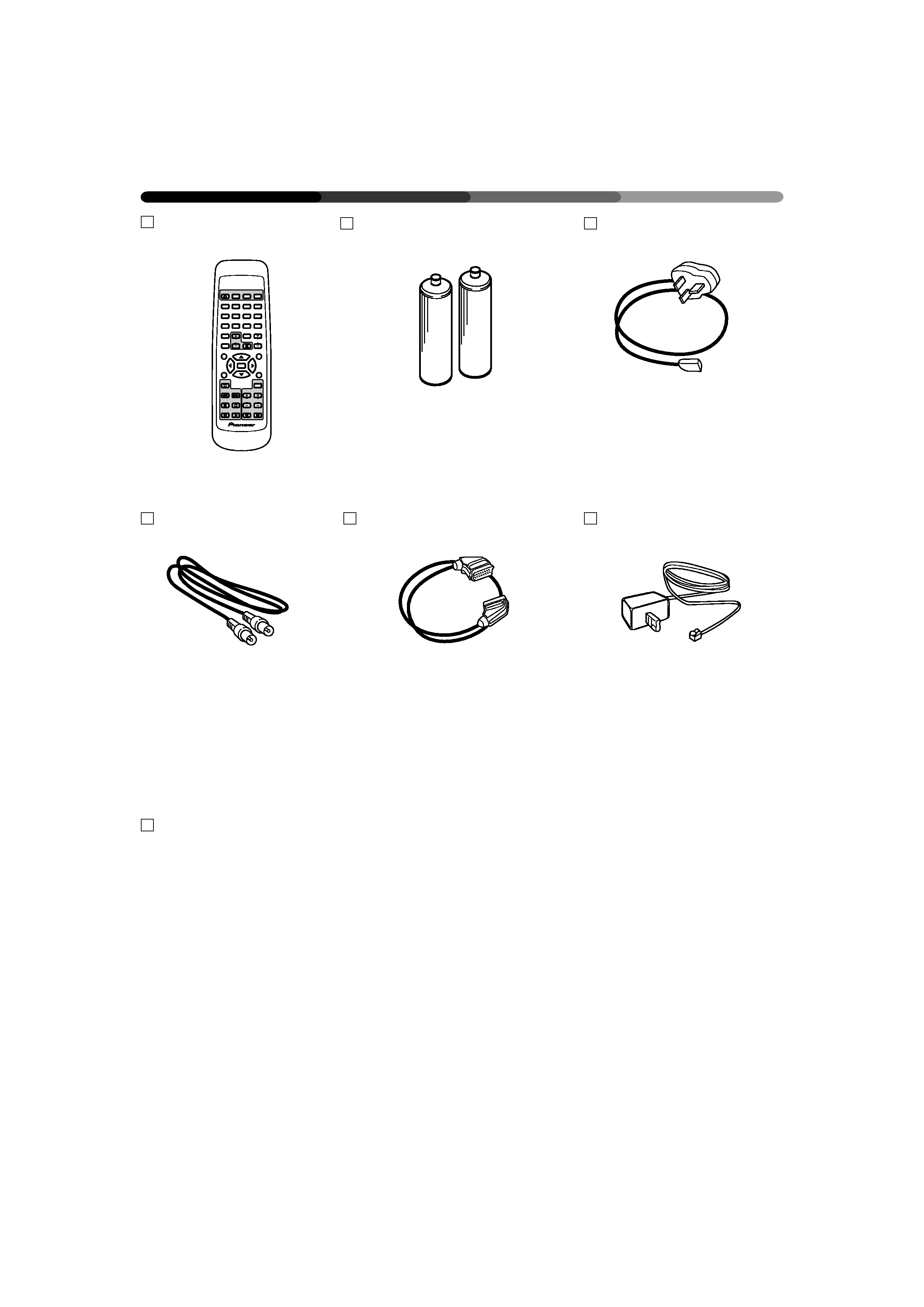
INCLUDED ACCESSORIES
Remote Control Unit
Two AA/RO6 or rob batteries
Mains lead
Aerial/RF lead
SCART lead
Telephone modem cable
ONdigital envelope (includes ONdigital Quick set up guide)
*A Smartcard is appended.
This is provided separately.
Plug it into the main power
supply.
Connects the ONdigital box to
the video or TV. (Refer to the
illustrations on the following
pages.)
Connects the TV SCART socket
to the ONdigital box SCART
socket. (SCART sockets are
usually labelled EXT or AV.)
The modem cable is provided
for future interactive services.
STANDBY
TEXT
VOL
12
3
45
6
78
0
9
TV/DTV
SUBTITLE
TV/VCR
STANDBY
STANDBY
WIDE
PRG
GUIDE
INFO
EXIT
TV
VCR
SEL
MENU
CH
VOL
5
<BRB1056>
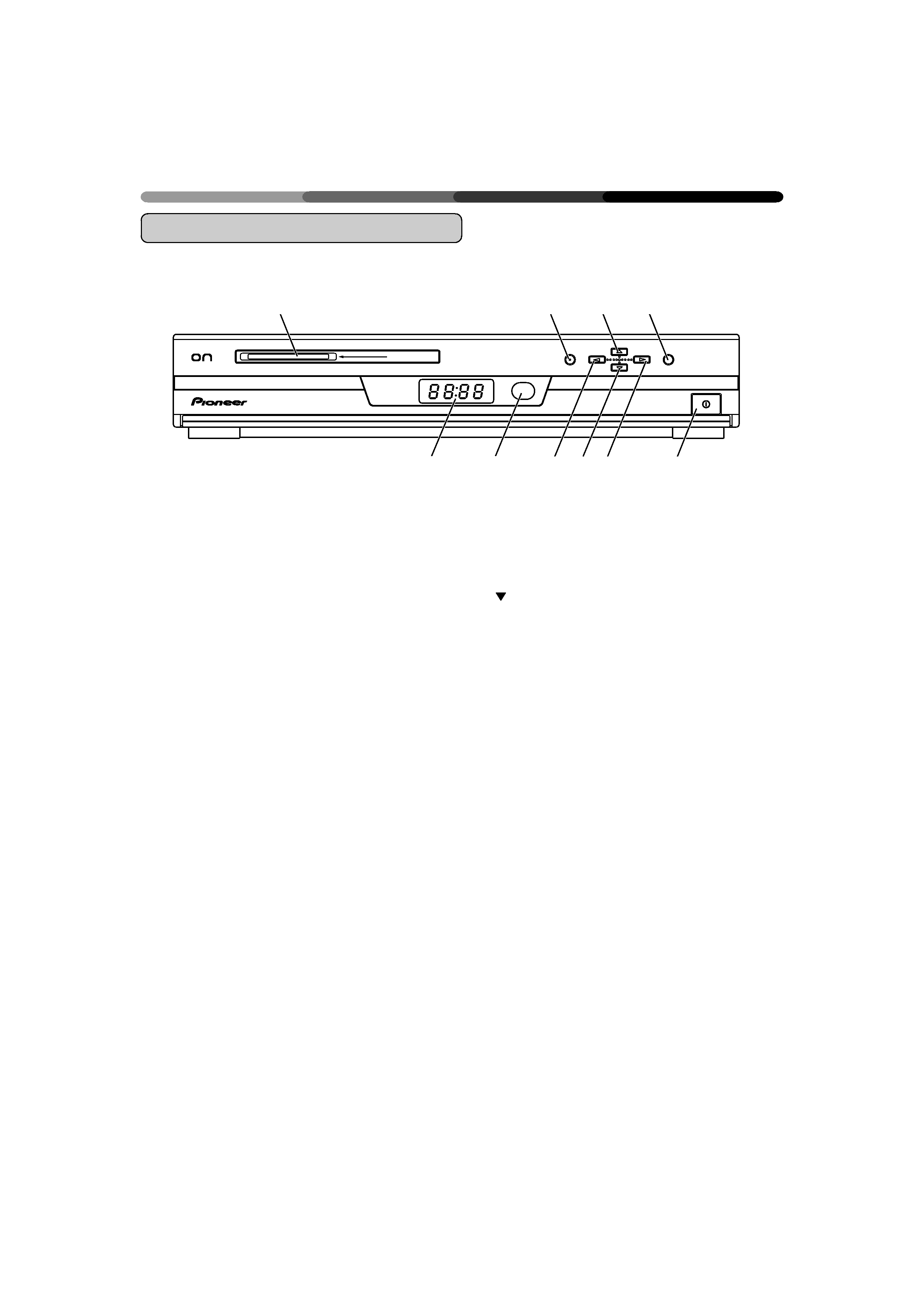
1 Smartcard slot
2 MENU button:
Displays and closes Main Menu
3
5 : Moves the highlight towards the top of
the menu
4 SELECT button:
Displays the channel list while in the TV
mode.
Confirms the menu selections
OPERATION PANEL FEATURES AND FUNCTIONS
Front and Back Panels
Front View (Front Panel)
5 4-digit LED front indicator light
6 Infrared sensor
7
2 : Adjusts menu option settings
8
: Moves the highlight towards the bottom
of the menu
9
3 : Adjusts menu option settings
0 Main Switch button
digital
DIGITAL TERRESTRIAL RECEIVER
SMART CARD
MENU
SELECT
ON/OFF
1
23
4
56
7 8 9
0