CP-ST100
CP-ST100_EN.book
1
2
En
Thank you for buying this Pioneer product. Please read through
these operating instructions for proper assembly and use. After
you have finished reading the instructions, put them away in a
safe place for future reference.
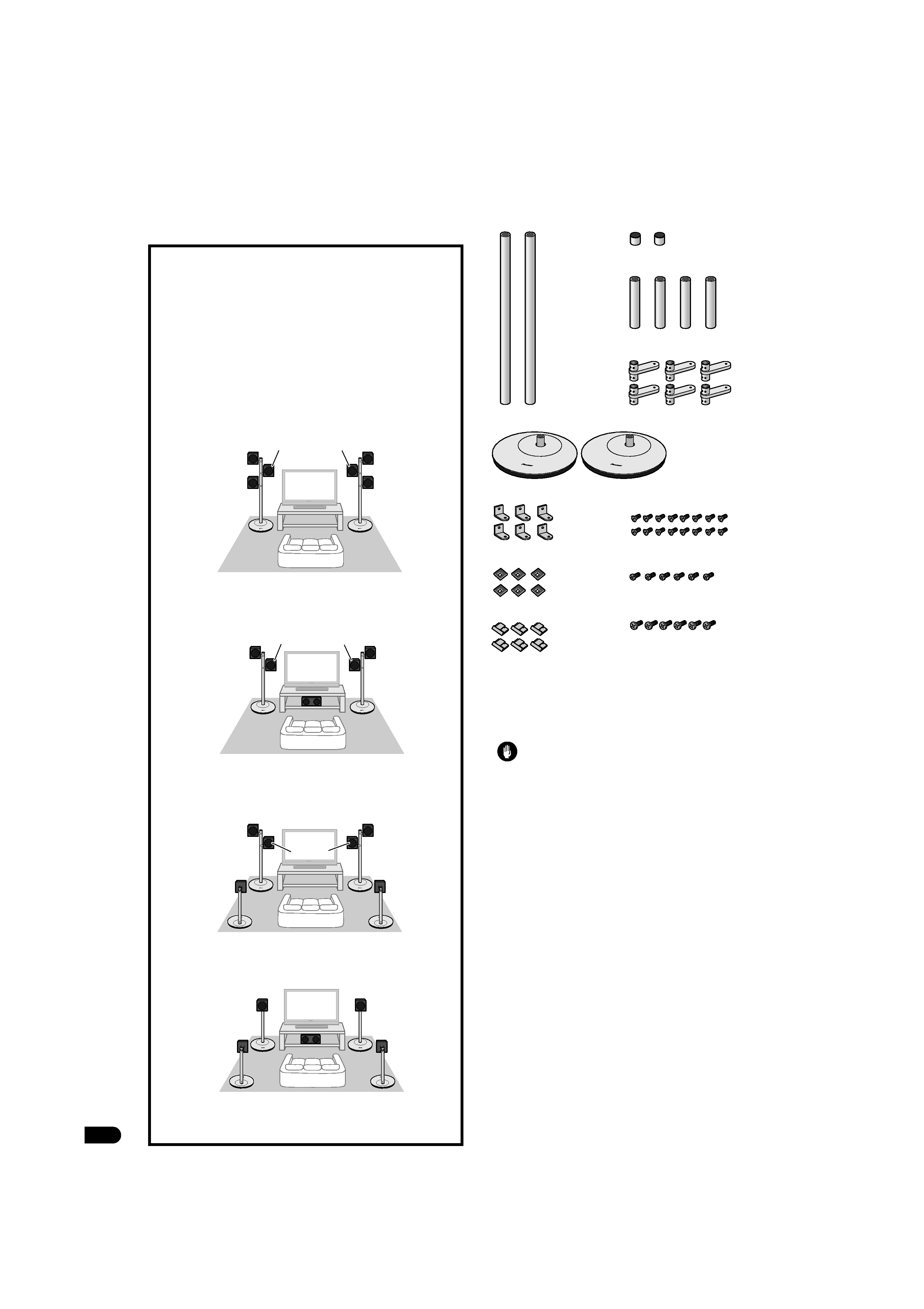
Confirm your Accessories
Before you start
Before setting up your speaker system, we recommend reading
the operating instructions for your system thoroughly.
Caution
· This stand has been designed to support weights up to
1.1 kg per arm, or a maximum of 3.3 kg (when 3 arms are
used). Exceeding these limits may result in falling or
breakage.
· Only use the screws supplied when fixing the speaker to the
speaker stand. Speakers may fall and incur damages if not
fixed in place properly.
· Do not use with any speaker system other than the one for
which the unit was designed. The stand may collapse and
be damaged and/or the speaker may fall and cause injury.
· Be careful when assembling and moving the speaker stand,
as it may cause damage or injury in the event of a fall.
· Placing the stand on an unstable surface can be dangerous.
Be sure to place it on a flat, firm surface.
· Make sure you assemble the stand on a flat surface that is
relatively soft (such as a carpet).
· Do not sit or stand on the speaker, or let children play on the
speaker. Doing so could provoke the speaker to fall, causing
damages or bodily injury.
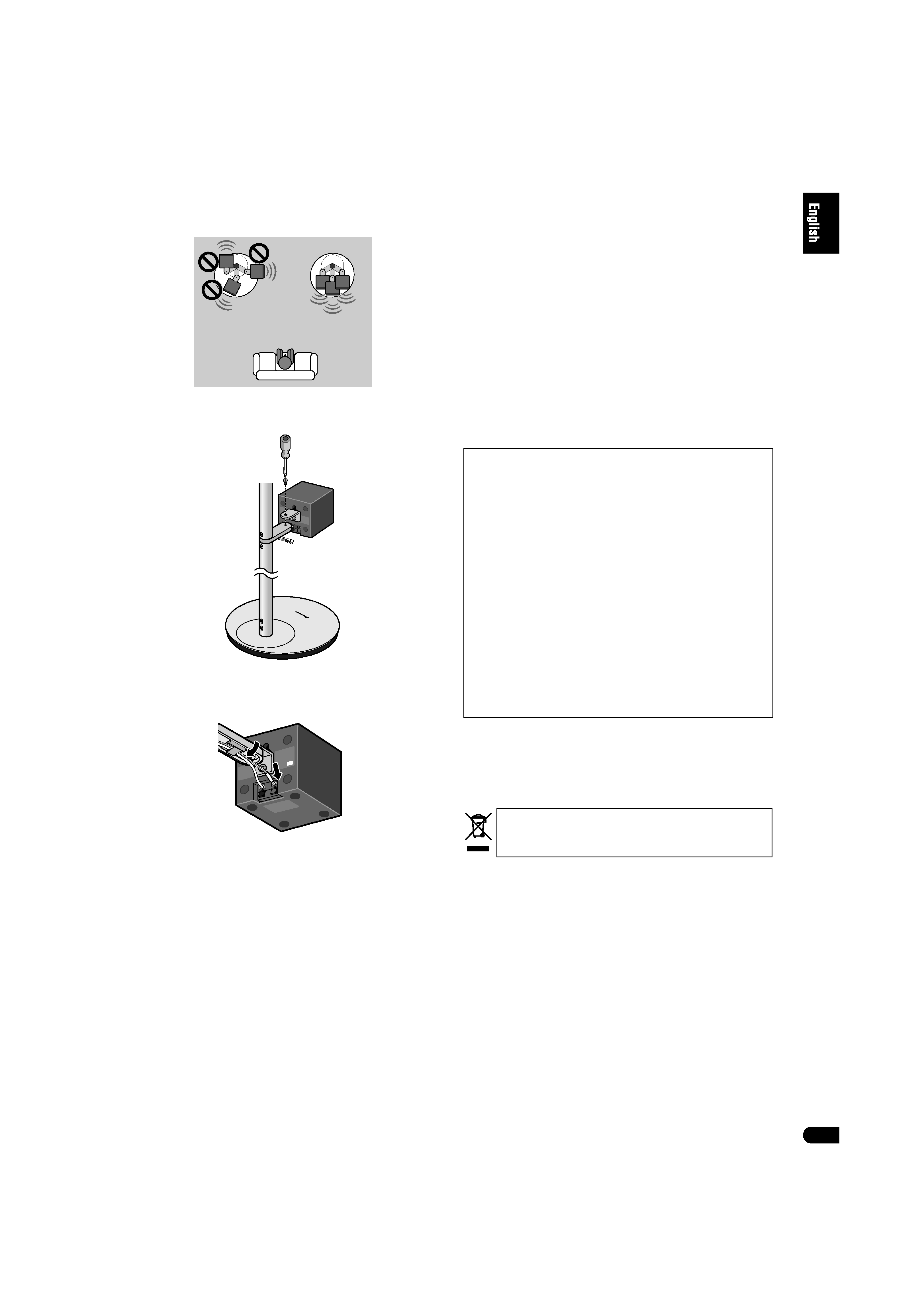
Assembly Hints
These stands have been designed to allow the mounting of up
to three speakers each, but the number actually mounted will
depend on the speaker system used (surround setting). When
assembling the stands, use only that number of support arms
actually required for the speakers to be mounted.
· For more information regarding various surround setups,
consult the owners manuals furnished with your speakers
and home theater system.
Setup examples:
· Additional stands will be required if they are used to
support surround (rear) speakers as well.
Listening position
· Front surround setup
(using dual center speakers)
Center
Front left
Front right
Center
Surround
left
Surround
right
Listening position
Center
· Front surround setup
Front left
Front right
Surround
left
Surround
right
Listening position
Center
· Standard surround setup
Surround
left
Surround
right
Front left
Front right
Listening position
· Standard surround setup
(using dual center speakers)
Surround
left
Surround
right
Front left
Front right
Center
· Screws (Flat countersunk head,
M4xL6), for assembling supports x 16
· Screws (Bind head, M4xL8), for
assembling arms x 6
· Screws (Bind head, M5xL10) for
mounting speakers x 6
· These operating instructions
· Supports (long) x 2
· Caps x 2
· Supports (short) x 4
· Arms x 6
· Stand bases x 2
· Angle brackets x 6
· Pad gaskets x 6
· Wire clips x 6
CP-ST100_EN.book
2
3
En
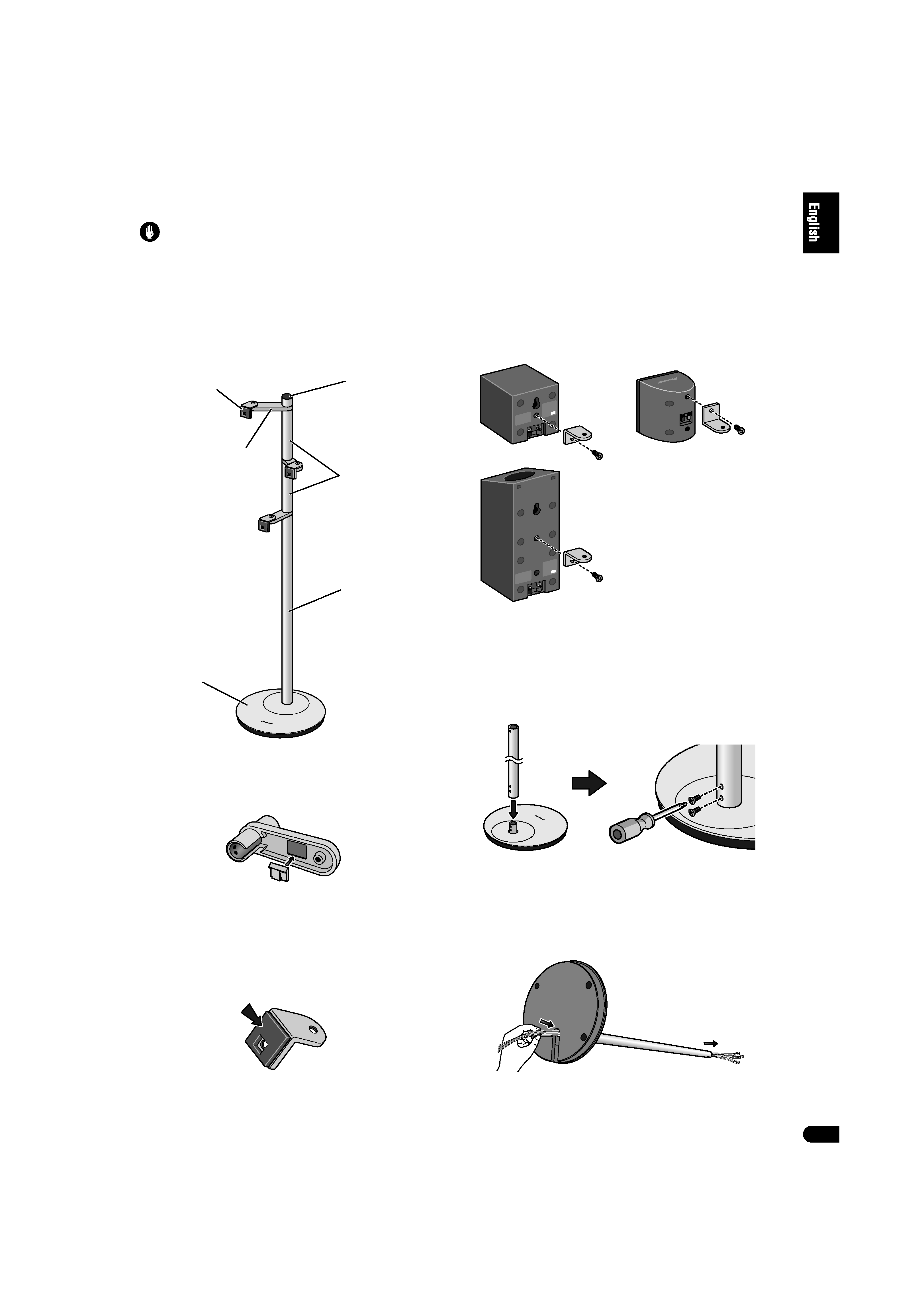
Assembling the speaker stands
Caution
· Pioneer is not responsible for any accidents or damage that
result from improper installation, misuse or modification of
the product, or natural disasters.
Assemble the speaker stands as illustrated below. Please note
that a medium-sized Phillips screwdriver is required for
assembly.
The accompanying illustration shows the fully assembled
speaker stand, without speakers or wires.
1 Fasten the wire clips to the arms.
Peel the protective paper backing from the clip and affix the
clip to the indentation on the underside of the arm as
shown.
2 Fasten angle brackets to speakers.
Peel the protective paper backing from the gasket and affix
the gasket to the angle bracket as shown.
· Affix the gasket to the square surface of the angle bracket. Be
sure to confirm the direction of the gasket so as to properly
align the gasket's hole with the screw hole in the angle
bracket.
Fasten the angle bracket to the speaker. Orient the gasket
material with the rear surface of the speaker, and align the
screw hole in the angle bracket with the speaker's screw
hole, then use the furnished screw (M5xL10) to securely
fasten the angle bracket to the speaker.
· In the event the speaker is furnished with two screw holes,
fasten the angle bracket to the upper of the two holes.
· The angle bracket has been originally designed to be
mounted with the rounded angle arm oriented upwards, but
in the event interference occurs with speaker terminals, the
rounded angle arm may also be mounted downward.
Speaker Installation Examples
3 Place a support (long) over the mounting post in the
stand base, and fasten securely with two countersunk
screws (M4xL6).
· The screw holes in the stand base are oriented to the rear
side.
· The support (long) is designed with specific up-down
orientation. Confirm the orientation before assembling.
4 Lay the stand on its side, and pass the speaker wires
into the hole in the stand base and through the
support.
Consult the owner's manual for the speaker system and
confirm the proper wires to be used (wires may be color
coded).
Stand base
Cap
Arms
Support (long)
Supports (short)
Angle brackets
(In the event of interference
between speaker terminals
and angle bracket)
CP-ST100_EN.book
3
4
En
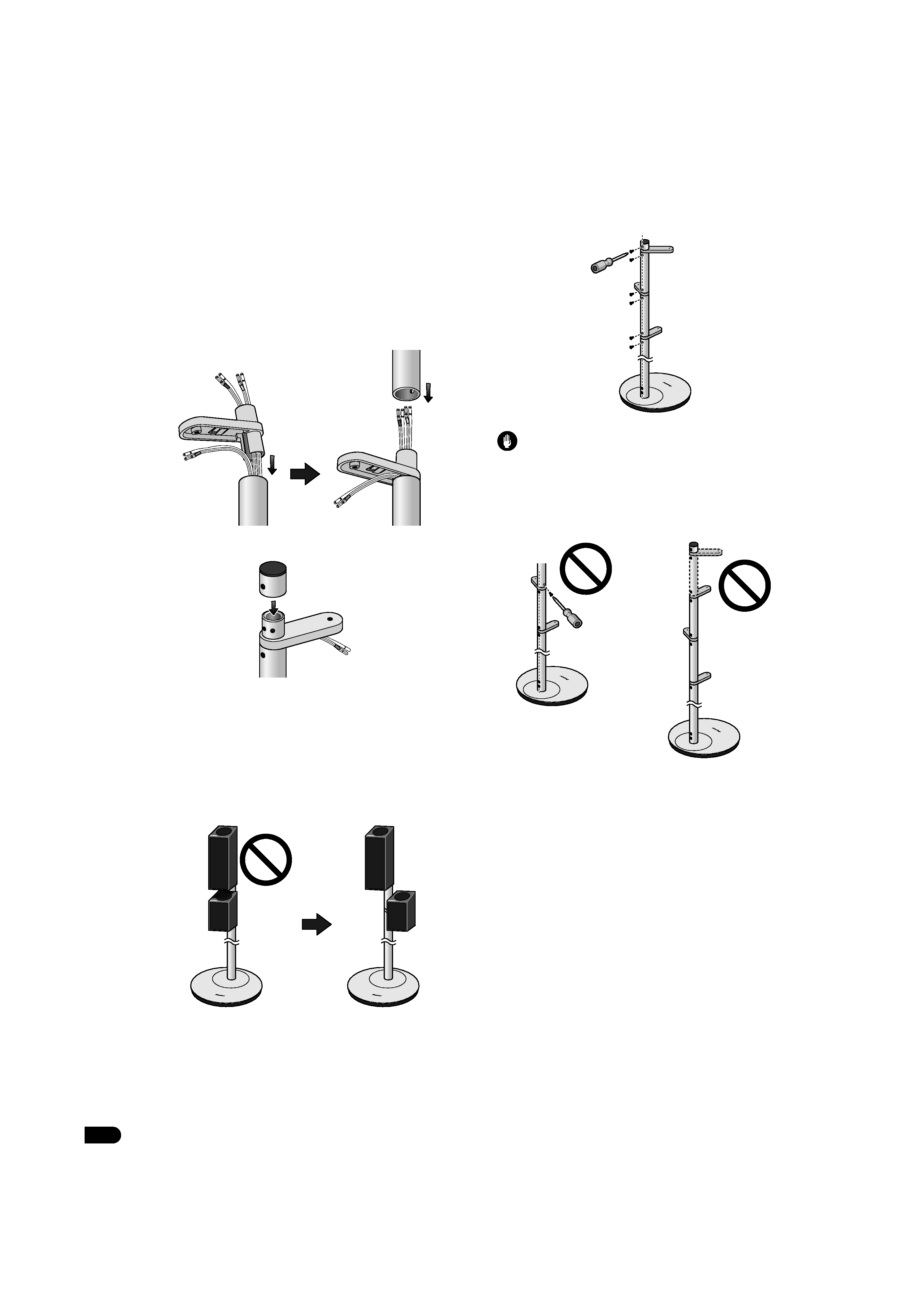
5 Assemble the arm and support (short) and pass each
speaker wire through in order as shown.
· The arms are designed with specific up-down orientation;
confirm that the side with the wire clip is oriented downward
during assembly.
Pass the appropriate speaker wire through each arm and
mount the assembled arms in order on the long support. In
the case of the speaker wire for the lowest arm, do not pass
the wire through the arm, but allow the wire to exit the
cutaway portion of the arm as shown, then affix a cap to the
top of the arm.
Place cap on top of uppermost arm.
6 Decide on the directional orientation for each
speaker, then fix in place with the furnished
countersunk screws.
· Each arm can mounted facing forward, or pointing 60° to
right or left. If a lower speaker unit has an upward-pointing
speaker, orient its direction away from the speaker above it.
When fixing the speakers in place, also consult the section
"Assembly Hints" on page 2.
Examples of stand with mounted speakers
Assemble the stands so that the screw holes in the supports
are all oriented toward the rear side of the stand, then insert
the furnished countersunk screws and tighten securely.
Caution
· Do not attempt to insert
screws when the supports
holes are oriented at a
diagonal angle from the
rear of the stand.
· Do not attempt to use more
than three arms on a single
stand, since the stand may
fall and cause damage or
injuries.
CP-ST100_EN.book
4
5
En
7 Fasten the speakers to the arms.
Be sure the speakers are oriented toward the listening
position when fastening in place.
Align the screw holes in the arm and angle bracket, and use
the furnished bind head screws (M4xL8) to fasten securely.
After fastening the speakers to the arms, attach each
speaker wire to its terminal on the rear of the speaker. Use
the wire clips to hold the wires in place as required.
Stand maintenance
With normal use, wiping with a soft cloth should be sufficient to
keep the stand clean. If necessary, clean with a cloth dipped in
a neutral cleanser diluted five or six times with water, and
wrung out well. Do not use furniture wax or cleansers. Never
use alcohol, thinners, benzine, insecticide sprays or other
chemicals on or near this unit since these will corrode the
surfaces. When using chemically-treated cloths, be sure to
carefully read their accompanying instruction manual.
Specifications
External dimensions (largest assembly)
............................300 mm (W) x 1113 mm (H) x 300 mm (D)
Weight (largest assembly).................................................. 5.8 kg
Supplied accessories
Stand bases [SXG1187] .............................................................. 2
Supports (long) [SNH1102] ........................................................ 2
Supports (short) [SNH1098]....................................................... 4
Caps [SXG1198]........................................................................... 2
Arms [SNH1099] ......................................................................... 6
Angle brackets [SNA1511] ......................................................... 6
Wire clips [SEP1381] .................................................................. 6
Pad gaskets [SEB1341]............................................................... 6
Screws (Flat countersunk head, M4xL6) [SBA1303].............. 16
Screws (Bind head, M4xL8) [SBA1304]..................................... 6
Screws (Bind head, M5xL10) [SBA1305]................................... 6
Operating instructions [SRD1366] ............................................ 1
The product numbers are listed above in square brackets.
· Specifications and design subject to possible modification
without notice, due to improvements.
Listening position
Replacement part numbers
Non-skid pads [SEB1343]
Screws (Bind head, M4xL12) [BPZ40P120FTB]
Screws (Bind head, M4xL8) [BMZ40P080FTB]
Polyethylene bag S2 [SHL1295]
Polyethylene bag S0 [SHL1314]
Polyethylene bag S0 [SHL1329]
Polyethylene bag S3 [SHL1429]
Polyethylene bag S0 [SHL1438]
Polyethylene bag S4 [SHL1457]
Polyethylene bag S0 [SHL1478]
Protection sheet [SHC1844]
Protector (Top) [SHA2633]
Protector (Bottom) [SHA2634]
Packing case [SHG2832]
If you want to dispose this product, do not mix it with general
household waste. There is a separate collection system for used
electronic products in accordance with legislation that requires
proper treatment, recovery and recycling.
Private households in the member states of the EU, in Switzerland and Norway
may return their used electronic products free of charge to designated
collection facilities or to a retailer (if you purchase a similar new one).
For countries not mentioned above, please contact your local authorities for
the correct method of disposal.
By doing so you will ensure that your disposed product undergoes the
necessary treatment, recovery and recycling and thus prevent potential
negative effects on the environment and human health.
Published by Pioneer Corporation.
Copyright © 2008 Pioneer Corporation.
All rights reserved.
CP-ST100_EN.book
5