ORDER NO.
CRT2150
Service
Manual
PUB. NO.
CRT2150
Manufactured for TOYOTA
by PIONEER ELECTRONIC CORPORATION
VEHICLE
DESTINATION
PRODUCED AFTER
TOYOTA PART No.
ID No.
PIONEER MODEL No.
TOYOTA
GERMANY, FRANCE,
JANUARY 1998
86270-60030
CDX-M8086ZT/E
LAND CRUISER
SWITZERLAND,
CDX-M8086ZT-91/E
100 SERIES
SAUDI ARABIA, OMAN,
U.A.E, KUWAIT
LEXUS LX470
SAUDI ARABIA, OMAN,
U.A.E, KUWAIT
TOYOTA
GREAT BRITAIN,
JANUARY 1998
86270-60030
CDX-M8186ZT/WL
LAND CRUISER
AUSTRALIA,
CDX-M8186ZT-91/WL
100 SERIES
NEW ZEALAND
LEXUS LX470,
AUSTRALIA,
NEW ZEALAND
LX470
TOYOTA
LAND CRUISER
100 SERIES
AUDIO SYSTEM
DISC PLAYER ASSY
2
CDX-M8086ZT,M8086ZT-91,M8186ZT,M8186ZT-91
- CD Player Service Precautions
1. For PU unit(CGY1036) handling,please refer to
"Disassembly"(Fig.20).
During replacement,handling precautions shall be
taken to prevent an electrostatic discharge(protection
by a short pin).
2. Be sure to turn the power off before disassembly. An
internal IC might be destroyed when a connector is
plugged or unplugged.
3. These CD players have been designed to be set
upright in a car. Therefore, when operating or adjust-
ing, set them upright.
- CDX-M8086ZT/E, CDX-M8086ZT-91/E, CDX-M8186ZT/WL, and CDX-M8186ZT-91/WL have adopted AVC-
LAN.
- The CD mechanism employed in this model is one of C3TV series.
- See the separate manual CX-624 (CRT1631) for the CD mechanism description and disassembly.
- See the separate manual CDX-P616/UC (CRT1632) for CD circuit description.
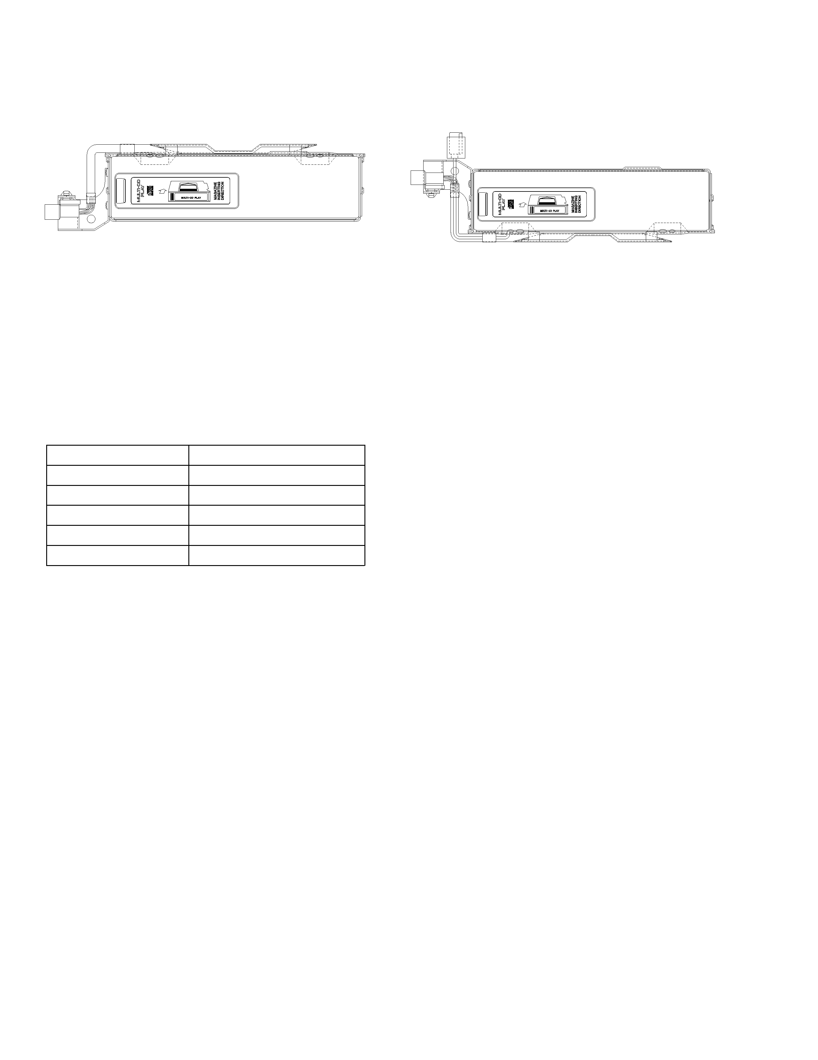
· CDX-M8086ZT/E
· CDX-M8186ZT/WL
CONTENTS
1. SAFETY INFORMATION ............................................3
2. EXPLODED VIEWS AND PARTS LIST .......................4
3. SCHEMATIC DIAGRAM ...........................................12
4. PCB CONNECTION DIAGRAM ................................22
5. ELECTRICAL PARTS LIST ........................................30
6. ADJUSTMENT..........................................................33
7. GENERAL INFORMATION .......................................43
7.1 IC ........................................................................43
7.2 DIAGNOSIS .......................................................45
7.2.1 SELF-DIAGNOSTIC FUNCTION..............45
7.2.2 DISASSEMBLY ........................................49
7.2.3 TEST MODE.............................................50
7.2.4 CONNECTOR FUNCTION DESCRIPTION ..51
7.3 EXPLANATION..................................................51
7.3.1 SYSTEM BLOCK DIAGRAM ...................51
7.3.2 BLOCK DIAGRAM ...................................52
8. OPERATIONS AND SPECIFICATIONS.....................54
- The supplementary models are identical with the original ones except for the following items.
Description
Part No.
Polyethylene Bag
CEG1249
Carton
CHG3495
Contain Box
CHL3495
Protector
CHP2028
Protector
CHP2029
3
CDX-M8086ZT,M8086ZT-91,M8186ZT,M8186ZT-91
1. SAFETY INFORMATION
This service manual is intended for qualified service technicians; it is not meant for the casual do-it-yourselfer.
Qualified technicians have the necessary test equipment and tools, and have been trained to properly and safely repair
complex products such as those covered by this manual.
Improperly performed repairs can adversely affect the safety and reliability of the product and may void the warranty.
If you are not qualified to perform the repair of this product properly and safely, you should not risk trying to do so
and refer the repair to a qualified service technician.
1. Safety Precautions for those who Service this Unit.
· Follow the adjustment steps (see pages 33 through 42)in the service manual when servicing this unit. When check-
ing or adjusting the emitting power of the laser diode exercise caution in order to get safe, reliable results.
Caution:
1. During repair or tests, minimum distance of 13cm from the focus lens must be kept.
2. During repair or tests, do not view laser beam for 10 seconds or longer.
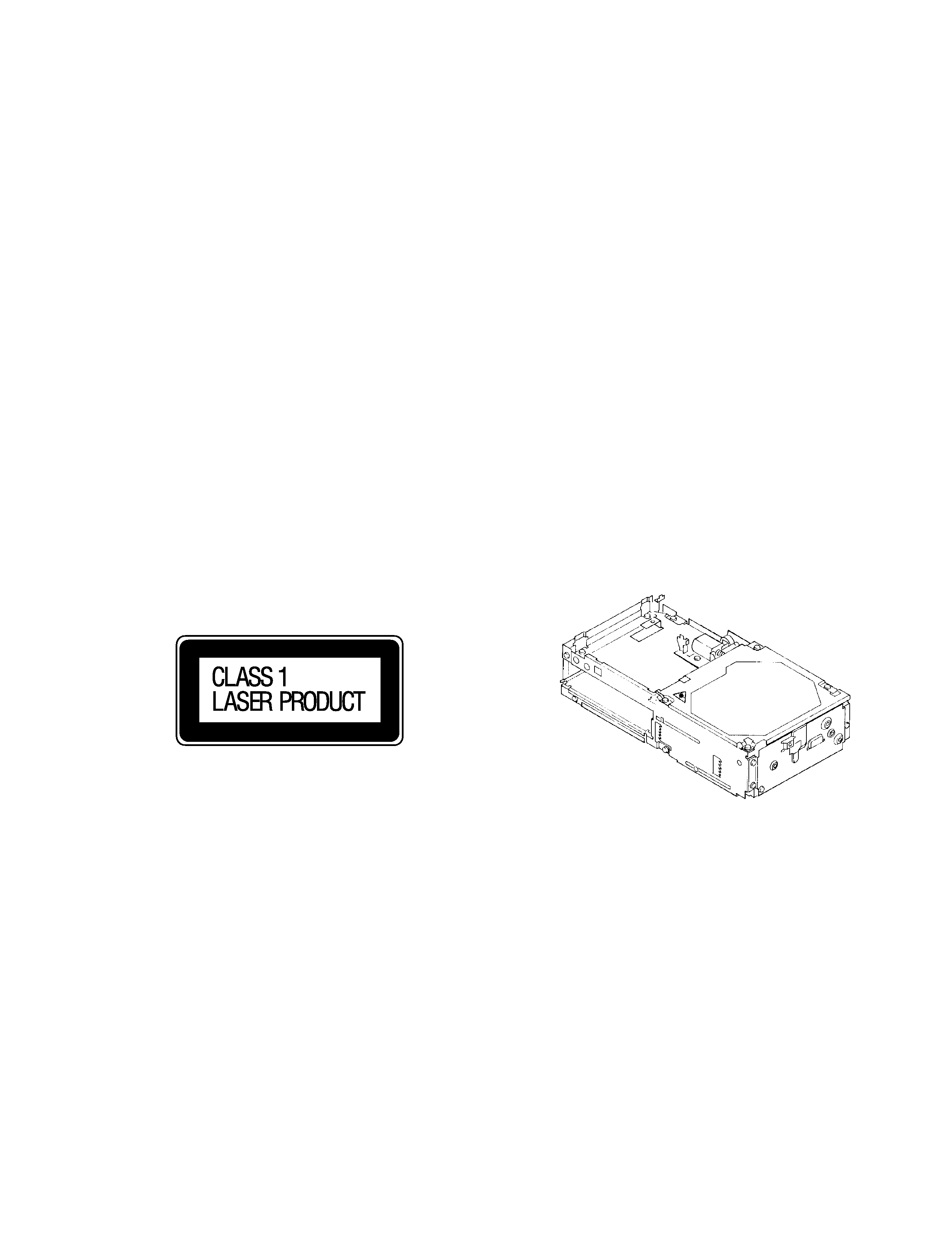
2. A "CLASS 1 LASER PRODUCT" label is affixed to the
rear of the player.
3. The triangular label is attached to the mechanism
unit frame.
4. Specifications of Laser Diode
Specifications of laser radiation fields to which human access is possible during service.
Wavelength
=
785 nanometers
Radiant power =
69.7 microwatts(Through a circular aperture stop having a diameter of 80 millimeters)
0.55 microwatts(Through a circular aperture stop having a diameter of 7 millimeters)
4
CDX-M8086ZT,M8086ZT-91,M8186ZT,M8186ZT-91
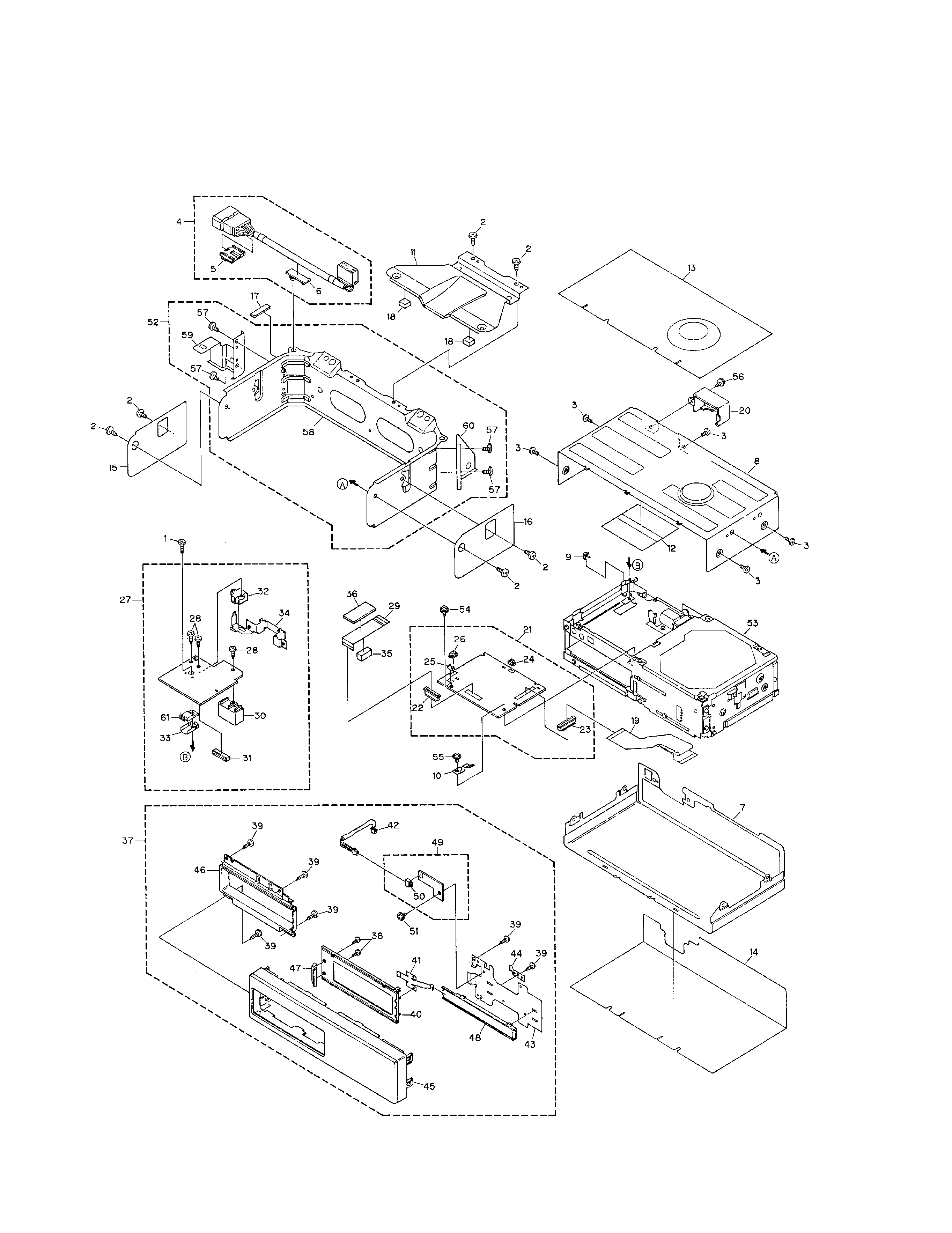
2. EXPLODED VIEWS AND PARTS LIST
2.1 EXTERIOR
- CDX-M8086ZT/E
Fig. 1

5
CDX-M8086ZT,M8086ZT-91,M8186ZT,M8186ZT-91
1 Screw
BMZ26P080FMC
2 Screw
BMZ40P060FMC
3 Screw
BSZ30P055FMC
4 Cord
CDE5651
5 82711-2B640
CNV5293
6 82711-16270
CNV5294
7 Case
CNB1987
8 Case
CNB2015
9 Earth Plate
CNC5769
10 Earth
CNC6340
11 Bracket
CNC7164
12 Insulator
CNM4428
13 Cushion
CNM5323
14 Cushion
CNM5324
15 Cushion
CNM5328
16 Cushion
CNM5329
*
17 Corrosive Cloth
CNM5828
18 Cushion
CNM5838
19 PCB
CNP3954
20 Holder
CNV4095
21 Main Unit
CWX2123
22 Connector(CN1701)
CKS2770
23 Connector(CN1801)
CKS2779
24 Connector(CN1803)
CKS3124
25 Connector(CN1702)
CKS3125
26 Connector(CN1802)
CKS3127
27 Extension Unit
CWX2126
28 Screw
CBA1339
29 Connector
CDE5009
30 Plug(CN901)
CKM1211
31 Connector(CN903)
CKS2224
32 Connector(CN951)
CKS3359
33 Heat Sink
CNC4447
34 Holder
CNC6544
35 Spacer
CNM4821
36 Spacer
CNM4822
37 Grille Assy
CXB1309
38 Screw
BPZ20P060FMC
39 Screw
BPZ26P080FMC
40 Door
CAT1882
41 Spring
CBL1162
42 Connector
CDE5370
*
43 Holder
CNC7128
44 Earth Plate
CNC7791
*
45 Grille
CNS4517
*
46 Sub Grille
CNS4518
*
47 Handle
CNS4544
48 Rail
CNV3487
49 Grille Unit
CWM5438
50 Plug(CN906)
CKS1050
51 Screw
IMS26P050FMC
52 Bracket Unit
CXB1367
53 CD Mechanism Unit
CXK4025
54 Screw
IMS20P030FMC
55 Screw
IMS26P040FMC
56 Screw
ISS30P080FZK
57 Screw
BMZ40P060FMC
*
58 Bracket
CNC7157
*
59 Bracket
CNC7158
*
60 Bracket
CNC7339
61 Transistor(Q911)
2SB942A
- EXTERIOR SECTION PARTS LIST
- CDX-M8086ZT/E
Mark No. Description
Part No.
Mark No. Description
Part No.
NOTE:
- Parts marked by "*"are generally unavailable because they are not in our Master Spare Parts List.
- Screws adjacent to
mark on the product are used for disassembly.