PIONEER ELECTRONIC CORPORATION
4-1, Meguro 1-Chome, Meguro-ku, Tokyo 153-8654, Japan
PIONEER ELECTRONICS SERVICE INC.
P.O.Box 1760, Long Beach, CA 90801-1760 U.S.A.
PIONEER ELECTRONIC [EUROPE] N.V.
Haven 1087 Keetberglaan 1, 9120 Melsele, Belgium
PIONEER ELECTRONICS ASIACENTRE PTE.LTD. 253 Alexandra Road, #04-01, Singapore 159936
C PIONEER ELECTRONIC CORPORATION 1999
K-ZZY. FEB. 1999 Printed in Japan
ORDER NO.
CRT2318
MULTI-COMPACT DISC PLAYER
CDX-P1250
X1N/UC
Service
Manual
CONTENTS
1. SAFETY INFORMATION ............................................3
2. EXPLODED VIEWS AND PARTS LIST .......................4
3. SCHEMATIC DIAGRAM ...........................................12
4. PCB CONNECTION DIAGRAM ................................20
5. ELECTRICAL PARTS LIST ........................................26
6. ADJUSTMENT..........................................................29
7. GENERAL INFORMATION .......................................35
7.1 IC .........................................................................35
7.2 DIAGNOSIS ........................................................40
7.2.1 DISASSEMBLY .........................................40
7.2.2 TEST MODE ..............................................42
7.3 BLOCK DIAGRAM ..............................................48
8. OPERATIONS AND SPECIFICATIONS.....................50
- See the separate manual CX-938(CRT2357) for the CD mechanism description, disassembly and circuit
description.
- The CD mechanism employed in this model is one of C8 series.
CDX-P1250/X1N/UC
CDX-P1250 X1N/EW
CDX-P1250 X1N/ES
2
CDX-P1250
- CD Player Service Precautions
1. For pickup unit(CXX1285) handling, please refer
to"Disassembly"(See page 40). During replacement,
handling precautions shall be taken to prevent an
electrostatic discharge(protection by a short pin).
2. During disassembly, be sure to turn the power off
since an internal IC might be destroyed when a con-
nector is plugged or unplugged.
3. Please checking the grating after changing the pickup
unit(see page 29) since these screws protects the
mechanism during transport, be sure to affix it when
it is transported for repair, etc.
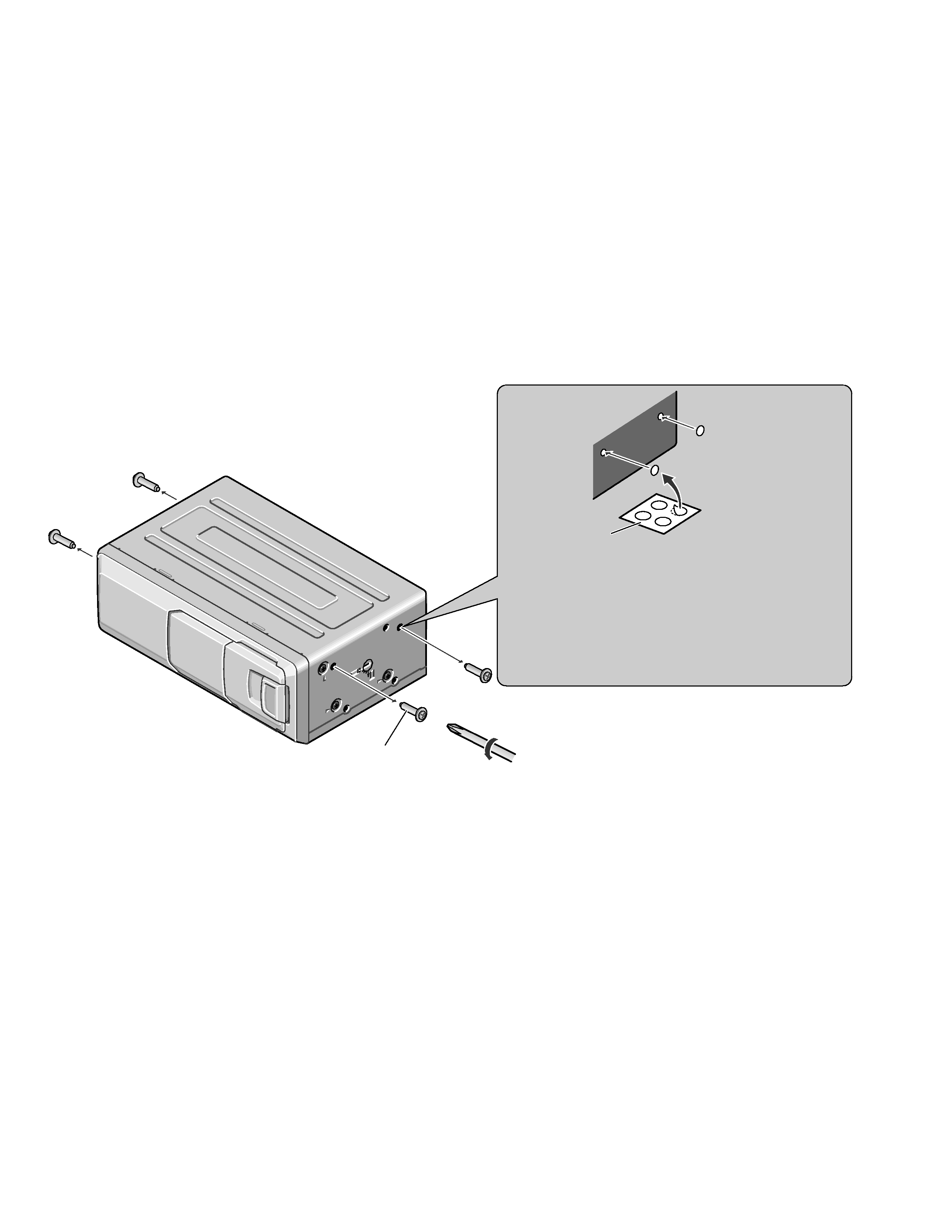
Transport screw
Attach to the original position before transporting the set.
Seal
After removing the transport screw, cover the hole
with the supplied seal.
Transportation of multi-CD Player
A transport screw has been attached to the set in order to protect it
during transportation. After removing the transport screw, cover
the hole with the supplied seal. Be sure to remove the transport
screw before mounting the set. The removed transport screw
should be retained in the accessory bag for use the next time the
set is transported.
3
CDX-P1250
1. SAFETY INFORMATION
1.1 CDX-P1250/X1N/UC
CAUTION
This service manual is intended for qualified service technicians; it is not meant for the casual do-it-yourselfer.
Qualified technicians have the necessary test equipment and tools, and have been trained to properly and safely repair
complex products such as those covered by this manual.
Improperly performed repairs can adversely affect the safety and reliability of the product and may void the warranty.
If you are not qualified to perform the repair of this product properly and safely; you should not risk trying to do so
and refer the repair to a qualified service technician.
WARNING
This product contains lead in solder and certain electrical parts contain chemicals which are known to the state of
California to cause cancer, birth defects or other reproductive harm.
Health & Safety Code Section 25249.6 - Proposition 65
1.2 CDX-P1250/X1N/EW
1. Safety Precautions for those who Service this Unit.
· Follow the adjustment steps (see pages 29 through 34)in the service manual when servicing this unit. When check-
ing or adjusting the emitting power of the laser diode exercise caution in order to get safe, reliable results.
Caution:
1. During repair or tests, minimum distance of 13cm from the focus lens must be kept.
2. During repair or tests, do not view laser beam for 10 seconds or longer.
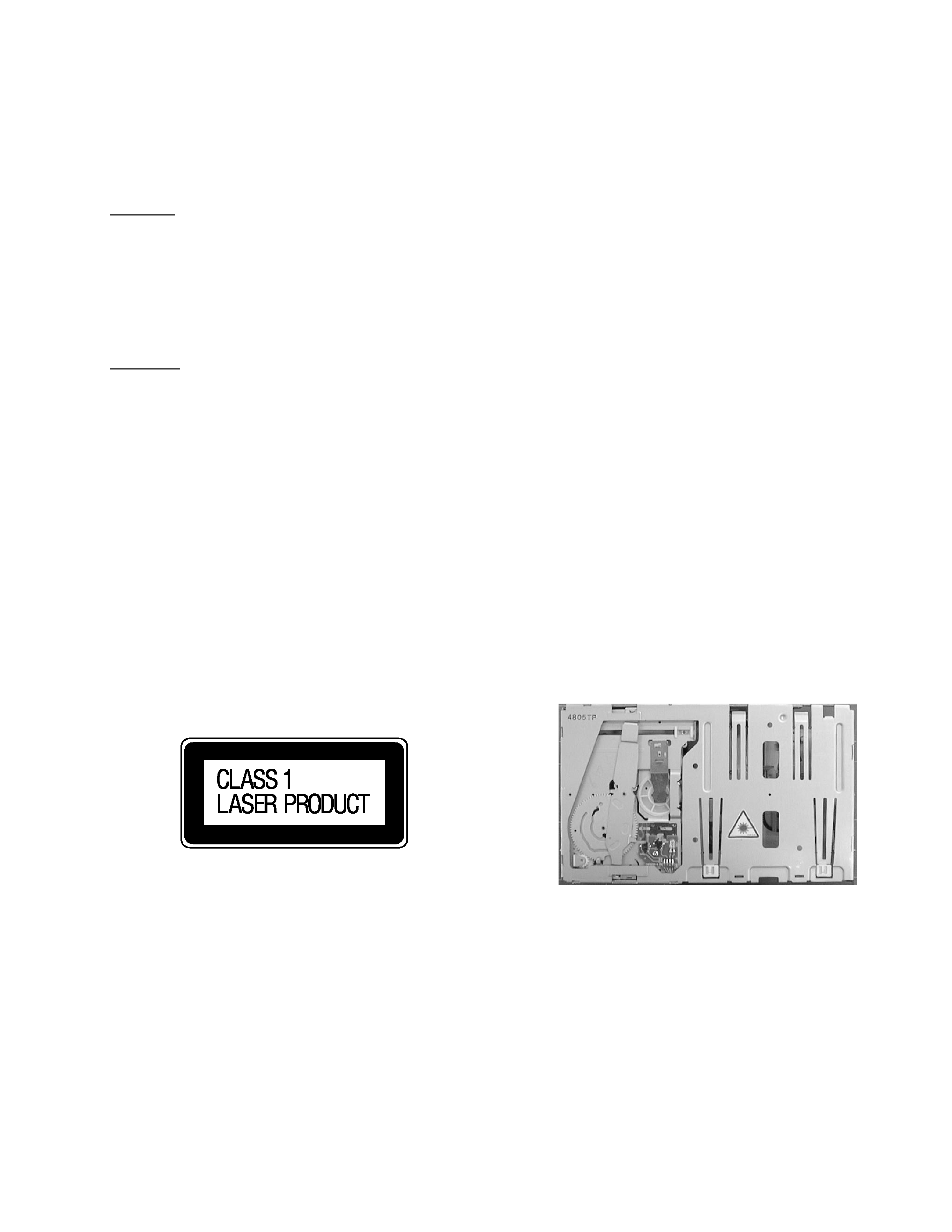
2. A "CLASS 1 LASER PRODUCT" label is affixed to the
rear of the player.
3. The triangular label is attached to the mechanism
unit frame.
4. Specifications of Laser Diode
Specifications of laser radiation fields to which human access is possible during service.
Wavelength
=
800 nanometers
4
CDX-P1250
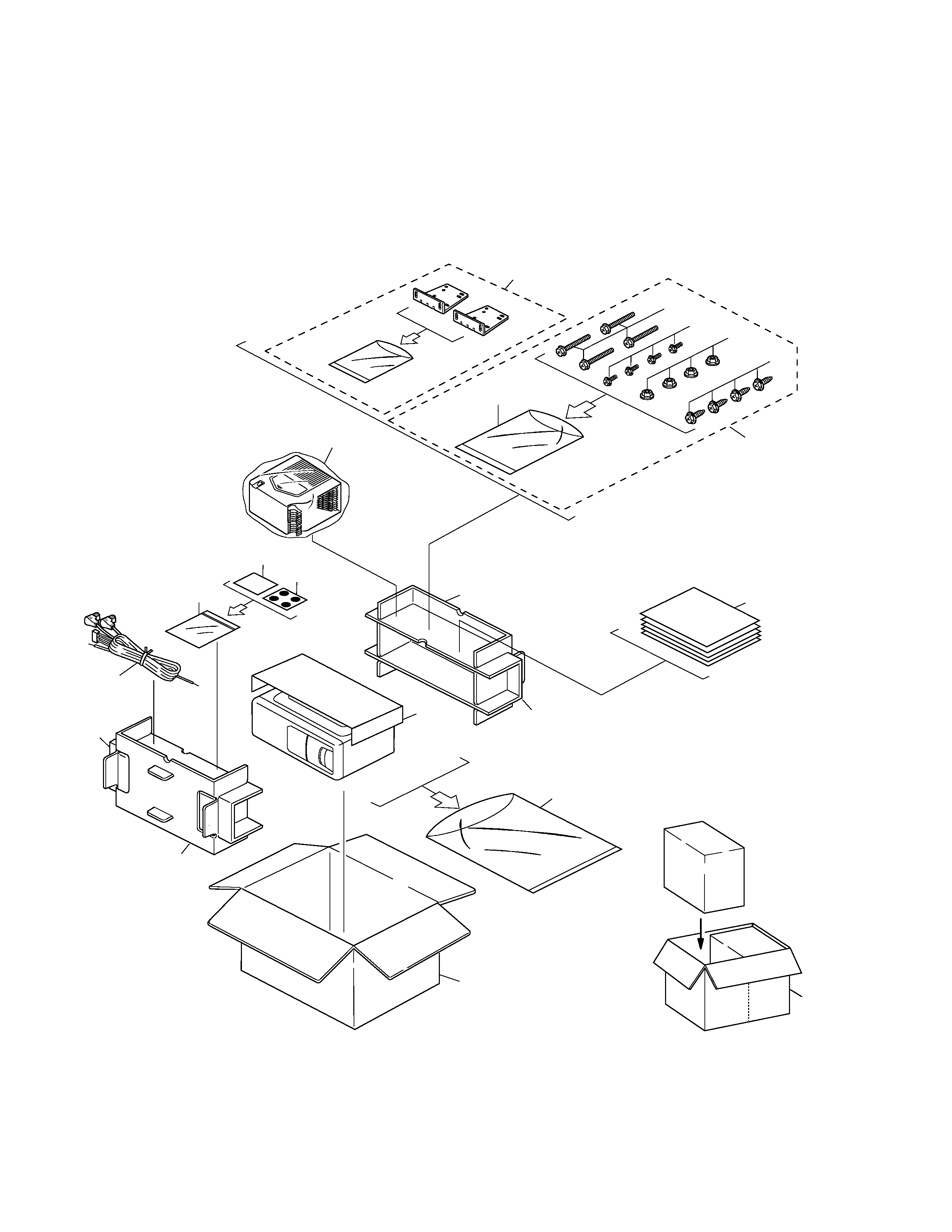
2. EXPLODED VIEWS AND PARTS LIST
2.1 PACKING
12
11
11
12
8
9
15
19
10
7
13
5
4
3
1
6
2
14
21
20
16
5
CDX-P1250
Part No.
Mark No. Description
CDX-P1250/X1N/UC
CDX-P1250/X1N/EW
CDX-P1250/X1N/ES
1 Screw Assy
CEA1962
CEA1962
CEA1962
2 Screw
CBA1295
CBA1295
CBA1295
*
3 Polyethylene Sheet
CNM5158
CNM5158
CNM5158
4 Screw
HMB60P500FMC
HMB60P500FMC
HMB60P500FMC
5 Screw
HMF40P080FZK
HMF40P080FZK
HMF40P080FZK
6 Nut
NF60FMC
NF60FMC
NF60FMC
*
7 Polyethylene Bag
CEG1099
CEG1099
CEG1099
8 Polyethylene Bag
CEG1174
CEG1026
CEG1026
9 Carton
CHG3717
CHG3718
CHG3719
10 Contain Box
CHL3717
CHL3718
CHL3719
11 Protector
CHP2136
CHP2136
CHP2136
12 Protector
CHP2137
CHP2137
CHP2137
13 Seal
CNM5599
CNM5741
CNM5741
14-1 Owner's Manual
CRD2895
CRD2896
CRD2898
14-2 Owner's Manual
Not used
CRD2897
CRB1533
* 14-3 Warranty Card
Not used
CRY1087
Not used
* 14-4 Caution Card
CRP1201
CRP1203
CRP1202
* 14-5 Caution Card
CRP1205
CRP1205
CRP1205
15 Magazine Assy
CXB4028
CXB4028
CXB4028
16 Angle Assy
CXB3589
CXB3590
CXB3590
17 ·····
18 ·····
19 Cord
CDE5831
CDE5830
CDE5831
*
20 Caution Card
CRP1090
CRP1090
CRP1090
*
21 Caution Card
CRP1196
CRP1196
CRP1196
- Owner's Manual
Model
Part No.
Language
CDX-P1250/X1N/UC
CRD2895
English, French
CDX-P1250/X1N/EW
CRD2896
English, Italian, French
CRD2897
German, Dutch, Spanish
CDX-P1250/X1N/ES
CRD2898
English, Spanish, Portuguese(B), Arabic
CRB1533
Chinese
- PACKING SECTION PARTS LIST
NOTE:
- Parts marked by "*"are generally unavailable because they are not in our Master Spare Parts List.
- Screws adjacent to
mark on the product are used for disassembly.