PIONEER CORPORATION
4-1, Meguro 1-Chome, Meguro-ku, Tokyo 153-8654, Japan
PIONEER ELECTRONICS (USA) INC.
P.O.Box 1760, Long Beach, CA 90801-1760 U.S.A.
PIONEER EUROPE NV
Haven 1087 Keetberglaan 1, 9120 Melsele, Belgium
PIONEER ELECTRONICS ASIACENTRE PTE.LTD. 253 Alexandra Road, #04-01, Singapore 159936
C PIONEER CORPORATION 2002
K-ZZA. JULY 2002 Printed in Japan
ORDER NO.
CRT2873
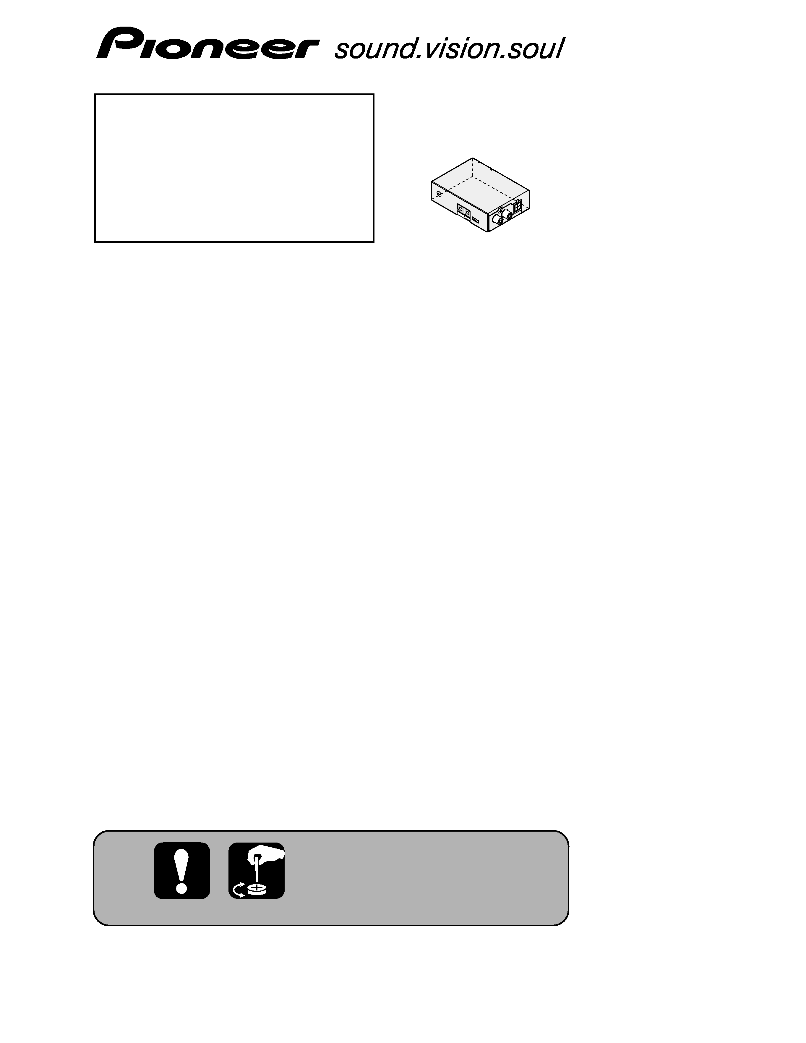
FM MODULATOR
CD-V61FM
E
Service
Manual
CD-V61FM/E
CONTENTS
1. SPECIFICATIONS........................................................3
2. EXPLODED VIEWS AND PARTS LIST .......................4
3. SCHEMATIC DIAGRAM .............................................6
4. PCB CONNECTION DIAGRAM ..................................8
5. ELECTRICAL PARTS LIST ........................................10
6. ADJUSTMENT..........................................................12
7. GENERAL INFORMATION .......................................15
7.1 IC ........................................................................15
8. OPERATIONS............................................................15
For details, refer to "Important symbols for good services".
2
1
234
12
34
F
E
D
C
B
A
CD-V61FM/E
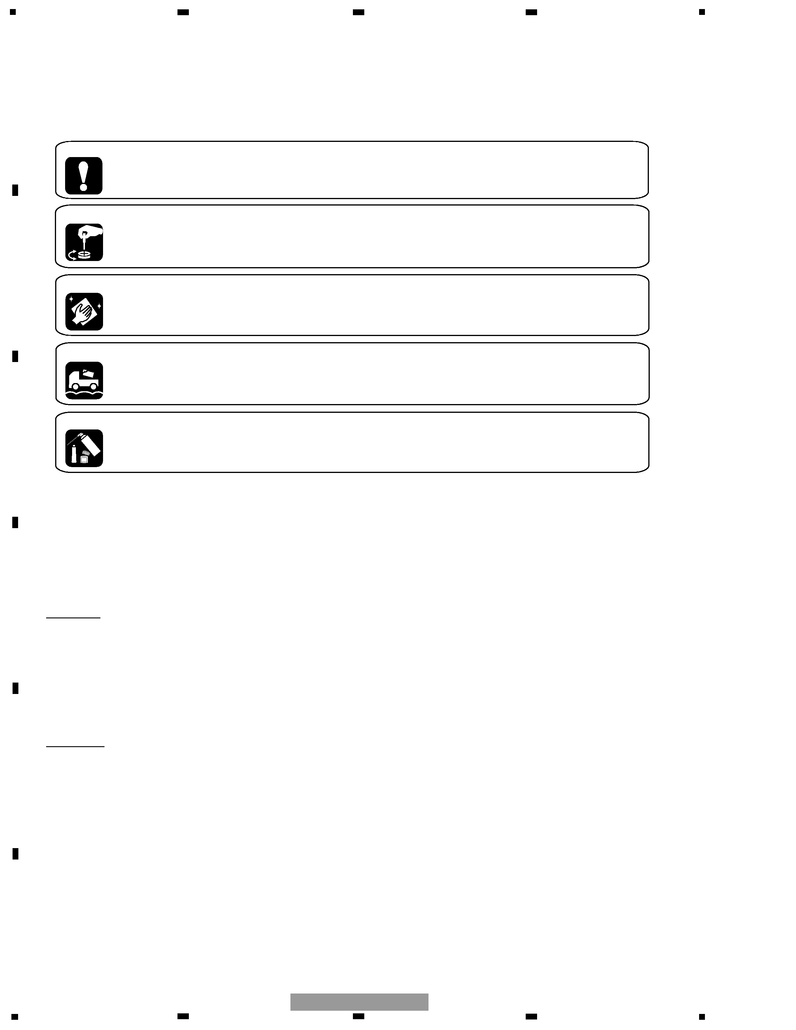
[ Important symbols for good services ]
In this manual, the symbols shown-below indicate that adjustments, settings or cleaning should be made securely.
When you find the procedures bearing any of the symbols, be sure to fulfill them:
2. Adjustments
To keep the original performances of the product, optimum adjustments or specification confirmation is indispensable.
In accordance with the procedures or instructions described in this manual, adjustments should be performed.
3. Cleaning
For optical pickups, tape-deck heads, lenses and mirrors used in projection monitors, and other parts requiring cleaning,
proper cleaning should be performed to restore their performances.
5. Lubricants, glues, and replacement parts
Appropriately applying grease or glue can maintain the product performances. But improper lubrication or applying
glue may lead to failures or troubles in the product. By following the instructions in this manual, be sure to apply the
prescribed grease or glue to proper portions by the appropriate amount.For replacement parts or tools, the prescribed
ones should be used.
4. Shipping mode and shipping screws
To protect the product from damages or failures that may be caused during transit, the shipping mode should be set or
the shipping screws should be installed before shipping out in accordance with this manual, if necessary.
1. Product safety
You should conform to the regulations governing the product (safety, radio and noise, and other regulations), and
should keep the safety during servicing by following the safety instructions described in this manual.
SAFETY INFORMATION
CAUTION
This service manual is intended for qualified service technicians; it is not meant for the casual do-it-yourselfer.
Qualified technicians have the necessary test equipment and tools, and have been trained to properly and safely repair
complex products such as those covered by this manual.
Improperly performed repairs can adversely affect the safety and reliability of the product and may void the warranty.
If you are not qualified to perform the repair of this product properly and safely, you should not risk trying to do so
and refer the repair to a qualified service technician.
WARNING
This product contains lead in solder and certain electrical parts contain chemicals which are known to the state of
California to cause cancer, birth defects or other reproductive harm.
Health & Safety Code Section 25249.6 - Proposition 65

3
5
6
7
8
F
E
D
C
B
A
5
6
7
8
CD-V61FM/E
Power source ....................... 14.4 V DC (10.8 15.1 V allowable)
Max. current consumption ............................................... 200 mA
Backup current ....................................................................... 0 mA
Weight .................................................................................... 220 g
Dimensions ...................................... 89 (W)
× 25 (H) × 64 (D) mm
FM modulator usable frequency .... 88.1/88.3/88.5/88.7/88.9/89.1
/89.3/89.5/89.7/89.9 MHz
Note:
Specifications and the design are subject to possible
modification without notice due to improvements.
1. SPECIFICATIONS
4
1
234
12
34
F
E
D
C
B
A
CD-V61FM/E
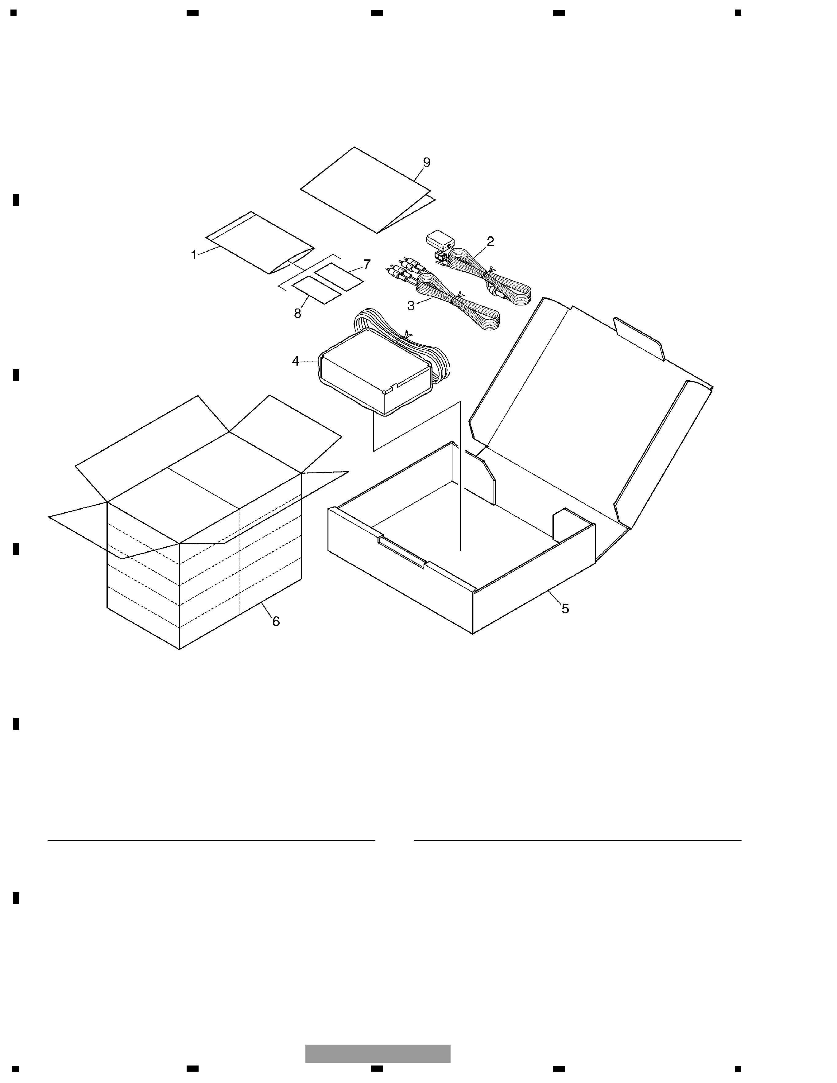
2. EXPLODED VIEWS AND PARTS LIST
2.1 PACKING
*
1 Polyethylene Bag
CEG1023
2 Cord Assy
CZD5356
3 Cord
CZD5357
4 Air Cushioned Bag
CZE3074
5 Carton
CZH5160
6 Contain Box
CZH5161
7 Magic Tape(Rough)
CZN5443
8 Magic Tape(Soft)
CZN5444
9 Owner's Manual
CZR3094
(English, Spanish, German, French, Italian,
Dutch, Traditional chinese)
Mark No. Description
Part No.
Mark No. Description
Part No.
- PACKING SECTION PARTS LIST
NOTE:
- Parts marked by "*" are generally unavailable because they are not in our Master Spare Parts List.
- Screws adjacent to
mark on the product are used for disassembly.
- For the applying amount of lubricants or glue, follow the instructions in this manual.
( In the case of no amount instructions, apply as you think it appropriate.)
5
5
6
7
8
F
E
D
C
B
A
5
6
7
8
CD-V61FM/E
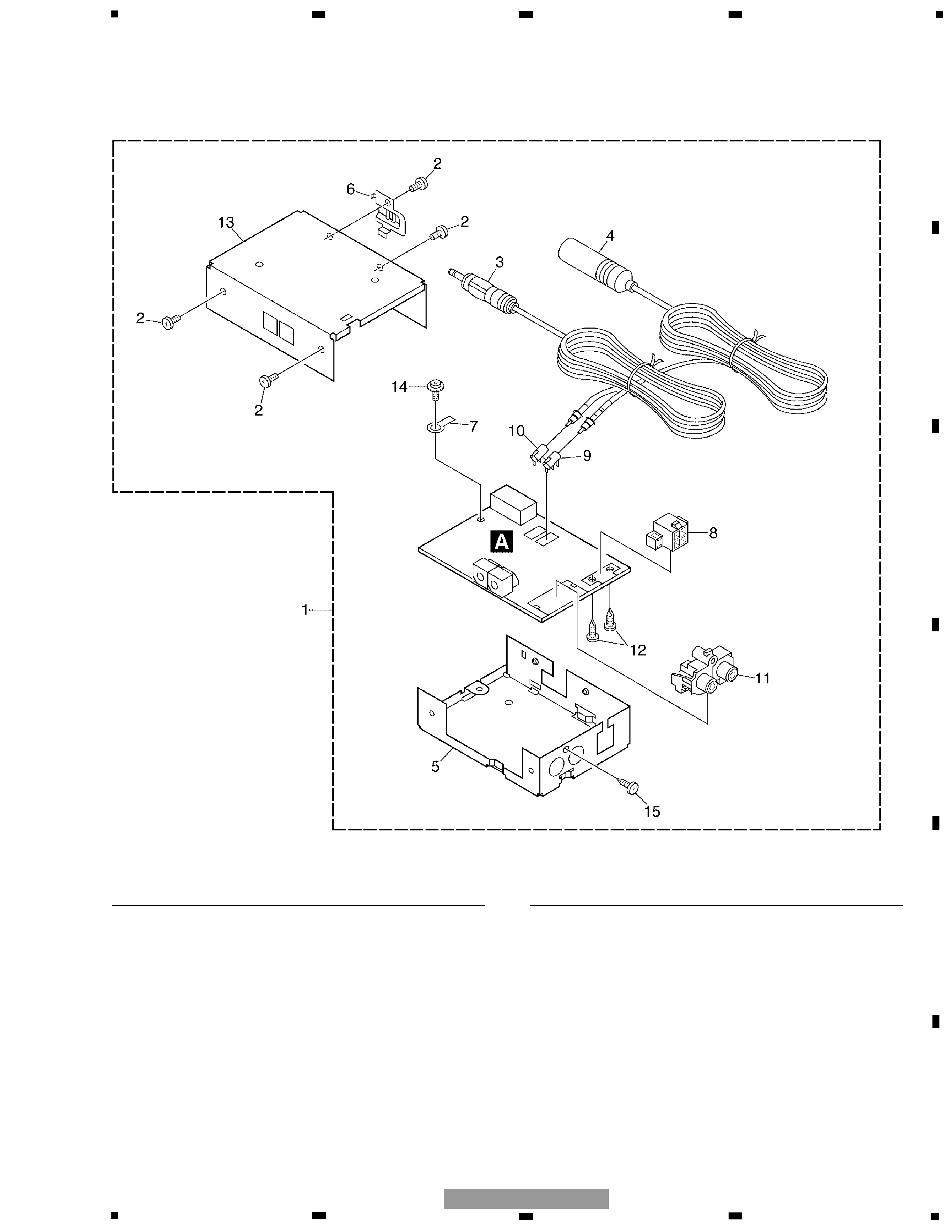
2.2 EXTERIOR
1 Modulator
CZX5028
2 Screw
BSZ30P050FMC
3 Antenna Cord
CZD5358
4 Antenna Cord
CZD5359
5 Chassis
CZN5448
6 Holder
CZN5449
7 Terminal(EP1)
CKF1064
8 Connector(CN403)
CKM1077
9 Antenna Jack(CN491)
CKX1010
10 Antenna Jack(CN492)
CKX1010
11 Pin Jack(J751)
CZK3065
12 Screw
PPZ26P080S-
13 Top Case Assy
CZX5039
14 Screw
ISS30P060FMC
15 Screw
PMZ30P080FNN
Mark No. Description
Part No.
Mark No. Description
Part No.
- EXTERIOR SECTION PARTS LIST