PIONEER CORPORATION
4-1, Meguro 1-Chome, Meguro-ku, Tokyo 153-8654, Japan
PIONEER ELECTRONICS SERVICE INC.
P.O.Box 1760, Long Beach, CA 90801-1760 U.S.A.
PIONEER EUROPE NV
Haven 1087 Keetberglaan 1, 9120 Melsele, Belgium
PIONEER ELECTRONICS ASIACENTRE PTE.LTD. 253 Alexandra Road, #04-01, Singapore 159936
C PIONEER CORPORATION 2001
K-ZZD. MAR. 2001 Printed in Japan
ORDER NO.
CRT2652
LEVEL INDICATOR CD PLAYER
CDS-P4000
UC
Service
Manual
- This service manual should be used together with the following manual(s):
Model No.
Order No.
Mech. Module Remarks
CX-977
CRT2624
S9
CD Mech. Module:Circuit Description, Mech.Description, Disassembly
CONTENTS
1. SAFETY INFORMATION ............................................2
2. EXPLODED VIEWS AND PARTS LIST .......................3
3. BLOCK DIAGRAM AND SCHEMATIC DIAGRAM .....8
4. PCB CONNECTION DIAGRAM ................................20
5. ELECTRICAL PARTS LIST ........................................28
6. ADJUSTMENT..........................................................31
7. GENERAL INFORMATION .......................................35
7.1 DIAGNOSIS ........................................................35
7.1.1 TEST MODE ..............................................35
7.1.2 DISASSEMBLY .........................................39
7.1.3 CONNECTOR FUNCTION DESCRIPTION44
7.2 PARTS .................................................................45
7.2.1 IC................................................................45
7.2.2 DISPLAY ....................................................51
7.3 OPERATIONAL FLOW CHART ...........................52
8. OPERATIONS AND SPECIFICATIONS.....................53

2
CDS-P4000
- CD Player Service Precautions
1. For pickup unit(CXX1480) handling, please refer
to"Disassembly"(see page 38).
During replacement, handling precautions shall be
taken to prevent an electrostatic discharge(protection
by a jumper-solder).
2. During disassembly, be sure to turn the power off
since an internal IC might be destroyed when a con-
nector is plugged or unplugged.
3. Please checking the grating after changing the ser-
vice pickup unit(see page 33).
CAUTION
This service manual is intended for qualified service technicians; it is not meant for the casual do-it-yourselfer.
Qualified technicians have the necessary test equipment and tools, and have been trained to properly and safely repair
complex products such as those covered by this manual.
Improperly performed repairs can adversely affect the safety and reliability of the product and may void the warranty.
If you are not qualified to perform the repair of this product properly and safely; you should not risk trying to do so
and refer the repair to a qualified service technician.
WARNING
This product contains lead in solder and certain electrical parts contain chemicals which are known to the state of
California to cause cancer, birth defects or other reproductive harm.
Health & Safety Code Section 25249.6 - Proposition 65
1. SAFETY INFORMATION
CDS-P4000
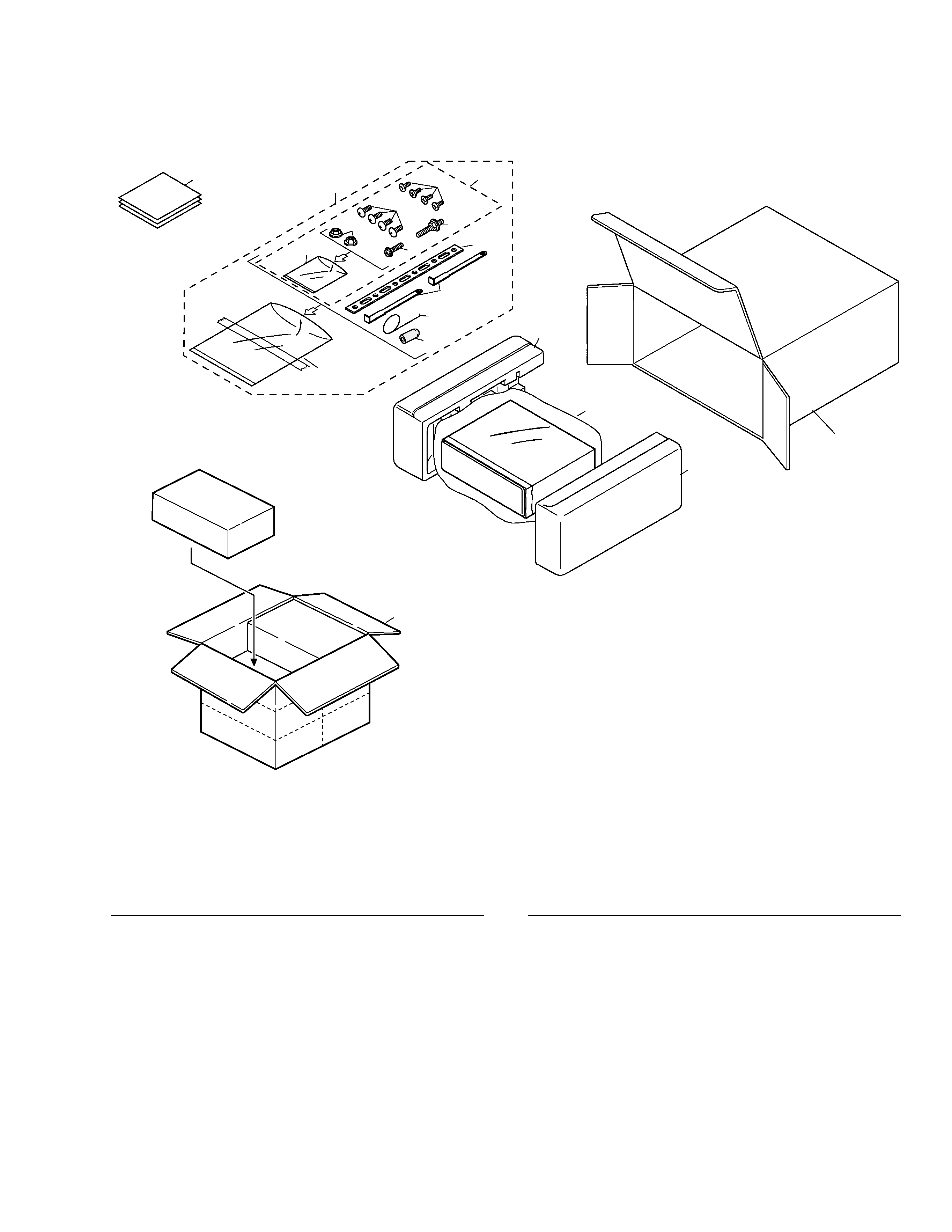
2. EXPLODED VIEWS AND PARTS LIST
2.1 PACKING
4
8
14
3
13
12
11
10
7
5
6
9
2
1,20,21,22
18
15
19
17
16
*
1 Card
ARY1048
2 Accessory Assy
CEA1918
3 Spring
CBH-865
4 Screw Assy
CEA1924
5 Screw
CBA-102
6 Screw
CBA1284
*
7 Polyethylene Sheet
CNM4338
8 Screw
CRZ50P090FMC
9 Nut
NF50FMC
10 Screw
TRZ50P080FMC
*
11 Polyethylene Bag
CEG-158
12 Handle
CNC5395
13 Strap
CNC5402
14 Bush
CNV1009
15 Polyethylene Bag
CEG1173
16 Carton
CHG4322
17 Contain Box
CHL4322
18 Protector
CHP1734
19 Protector
CHP1735
20 Owner's Manual(English) CRB1631
21 Installation Manual(English) CRB1632
*
22 Caution Card
CRP1247
Mark No. Description
Part No.
Mark No. Description
Part No.
- PACKING SECTION PARTS LIST
NOTE:
- Parts marked by "*" are generally unavailable because they are not in our Master Spare Parts List.
- Screws adjacent to
mark on the product are used for disassembly.
3
4
CDS-P4000
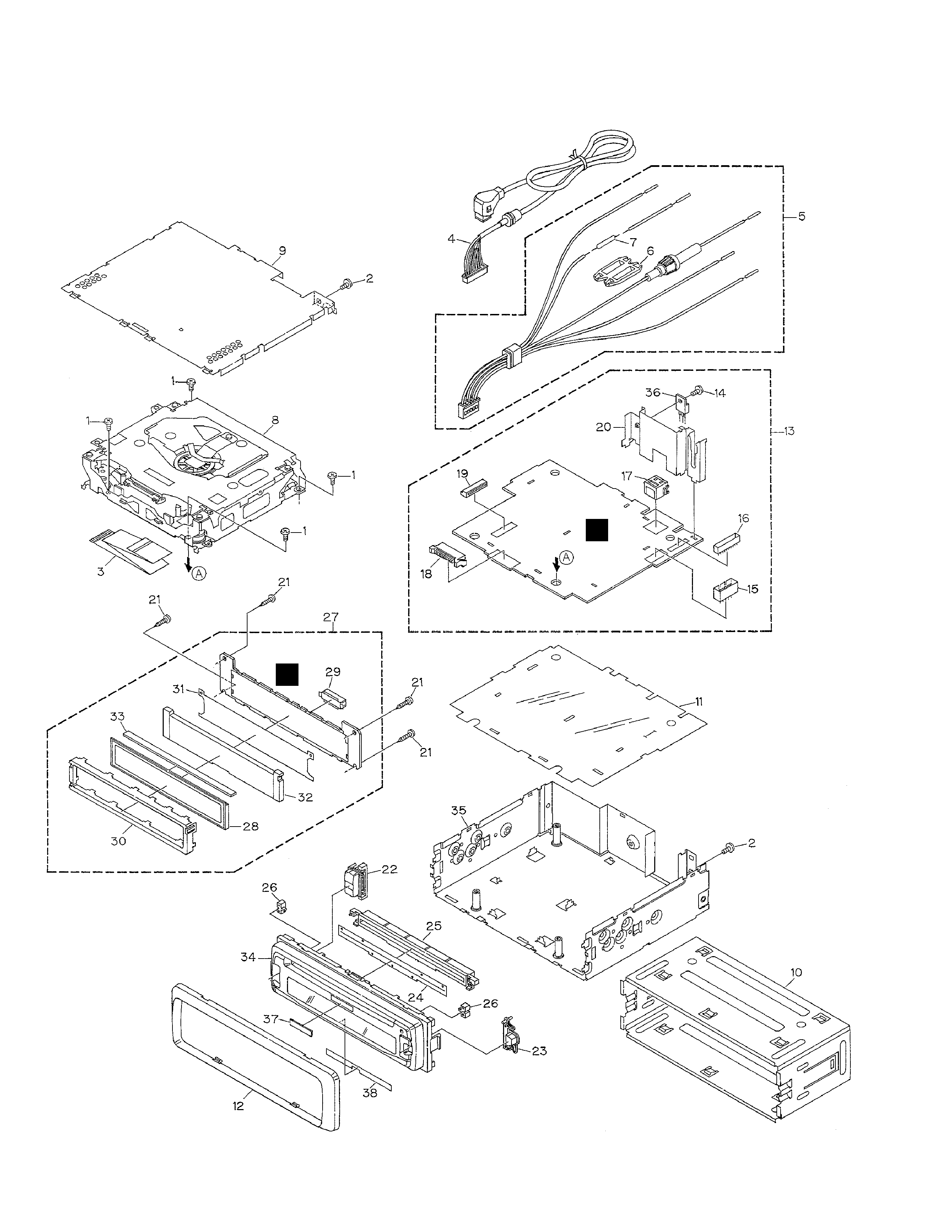
2.3 EXTERIOR
A
B

CDS-P4000
1 Screw
BSZ26P060FMC
2 Screw
BSZ30P060FMC
3 Cable
CDE6471
4 Cord Assy
CDE6474
5 Cord Assy
CDE6475
6 Cap
CNS1472
7 Resistor
RS1/2PMF102J
8 CD Mechanism Module(S9) CXK5500
9 Case
CNB2626
10 Holder
CNC8659
11 Insulator
CNM7062
12 Panel
CNS6344
13 Main Unit
CWM7488
14 Screw
BSZ26P080FMC
15 Connector(CN112)
CKM1193
16 Plug(CN103)
CKS1044
17 Connector(CN104)
CKS3408
18 Plug(CN107)
CKS3537
19 Connector(CN105)
CKS3835
20 Holder
CNC9139
21 Screw
BPZ20P080FMC
22 Button(DISPLAY)
CAC6886
23 Button(EJECT)
CAC6887
24 Cover
CNM7063
25 Holder
CNV6565
26 Lighting Conductor
CNV6566
27 Keyboard Unit
CWM7489
28 LCD(LCD901)
CAW1638
29 Socket(CN901)
CKS3550
30 Holder
CNC9137
31 Sheet
CNM7064
32 Lighting Conductor
CNV6567
33 Connector
CNV6568
34 Grille Unit
CXB6671
35 Chassis Unit
CXB6673
36 Transisitor(Q201)
2SD2396
*
37 Badge
CAH1754
*
38 Spacer
CNM7399
- EXTERIOR SECTION PARTS LIST
Mark No. Description
Part No.
5