PIONEER CORPORATION
4-1, Meguro 1-Chome, Meguro-ku, Tokyo 153-8654, Japan
PIONEER ELECTRONICS (USA) INC.
P.O.Box 1760, Long Beach, CA 90801-1760 U.S.A.
PIONEER EUROPE NV
Haven 1087 Keetberglaan 1, 9120 Melsele, Belgium
PIONEER ELECTRONICS ASIACENTRE PTE.LTD. 253 Alexandra Road, #04-01, Singapore 159936
C PIONEER CORPORATION 2002
K-ZZA. AUG. 2002 Printed in Japan
ORDER NO.
CRT2875
PLAYER-CD
Service
Manual
MAZDA
CDS-4027ZM/E
CDS-4027ZM
E
VEHICLE
DESTINATION
PRODUCED AFTER
MAZDA PART No.
ID No.
PIONEER MODEL No.
Not specified
U.S.A., CANADA,
September 2002
GJ6B79AGXA
CDS-4027ZM/E
EUROPE,
AUSTRALIA,
SWEDEN,
NEW ZEALAND,
HONGKONG
For details, refer to "Important symbols for good services".
2
1
234
12
34
F
E
D
C
B
A
CDS-4027ZM/E
SAFETY INFORMATION
This service manual is intended for qualified service technicians; it is not meant for the casual do-it-yourselfer.
Qualified technicians have the necessary test equipment and tools, and have been trained to properly and safely repair
complex products such as those covered by this manual.
Improperly performed repairs can adversely affect the safety and reliability of the product and may void the warranty.
If you are not qualified to perform the repair of this product properly and safely, you should not risk trying to do so
and refer the repair to a qualified service technician.
1. Safety Precautions for those who Service this Unit.
· When checking or adjusting the emitting power of the laser diode exercise caution in order to get safe, reliable
results.
Caution:
1. During repair or tests, minimum distance of 13cm from the focus lens must be kept.
2. During repair or tests, do not view laser beam for 10 seconds or longer.
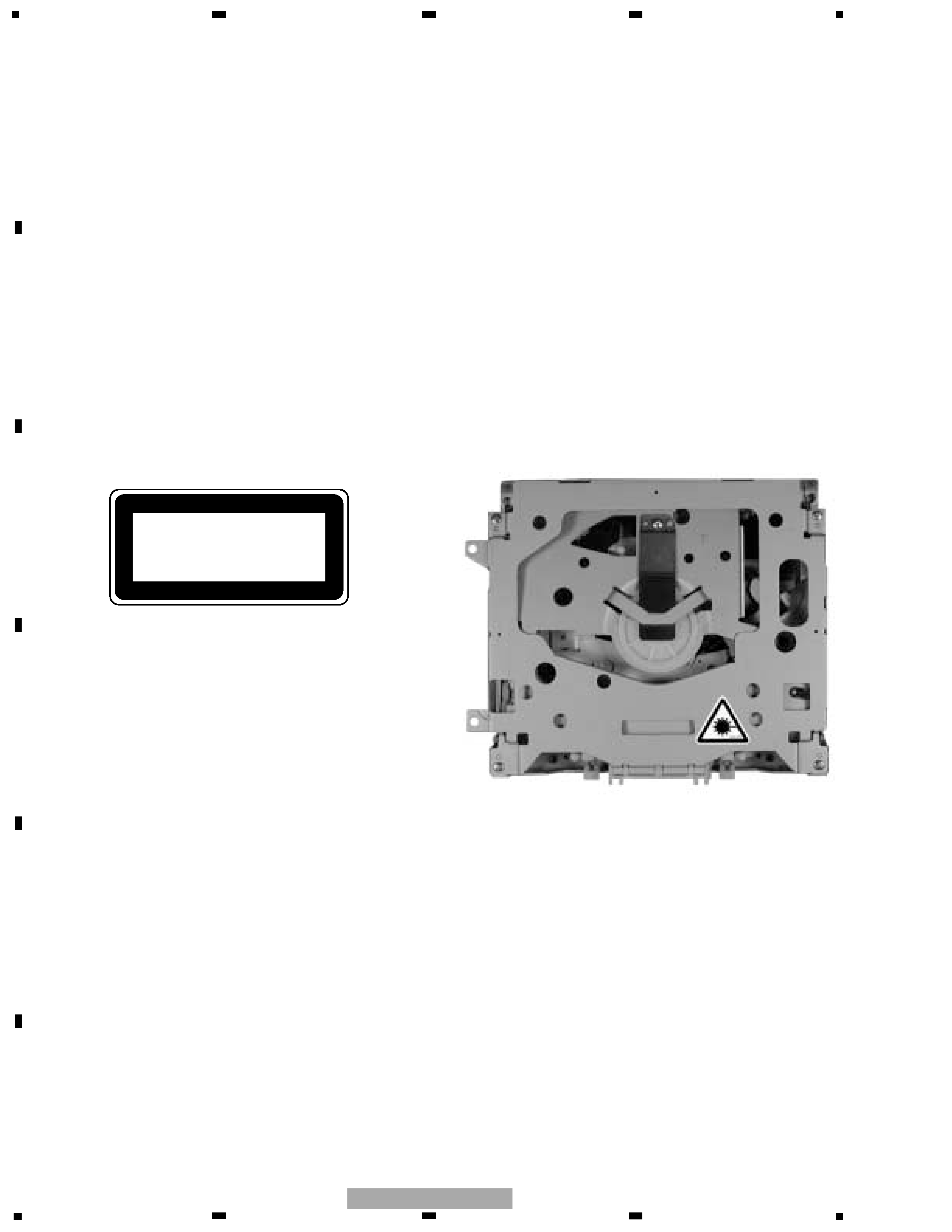
2. A "CLASS 1 LASER PRODUCT" label is affixed to the
bottom of the player.
3. The triangular label is attached to the mechanism
unit frame.
4. Specifications of Laser Diode
Specifications of laser radiation fields to which human access is possible during service.
Wavelength
=
800 nanometers
CLASS 1
LASER PRODUCT
3
5
6
7
8
F
E
D
C
B
A
5
6
7
8
CDS-4027ZM/E
[ Important symbols for good services ]
In this manual, the symbols shown-below indicate that adjustments, settings or cleaning should be made securely.
When you find the procedures bearing any of the symbols, be sure to fulfill them:
2. Adjustments
To keep the original performances of the product, optimum adjustments or specification confirmation is indispensable.
In accordance with the procedures or instructions described in this manual, adjustments should be performed.
3. Cleaning
For optical pickups, tape-deck heads, lenses and mirrors used in projection monitors, and other parts requiring cleaning,
proper cleaning should be performed to restore their performances.
5. Lubricants, glues, and replacement parts
Appropriately applying grease or glue can maintain the product performances. But improper lubrication or applying
glue may lead to failures or troubles in the product. By following the instructions in this manual, be sure to apply the
prescribed grease or glue to proper portions by the appropriate amount.For replacement parts or tools, the prescribed
ones should be used.
4. Shipping mode and shipping screws
To protect the product from damages or failures that may be caused during transit, the shipping mode should be set or
the shipping screws should be installed before shipping out in accordance with this manual, if necessary.
1. Product safety
You should conform to the regulations governing the product (safety, radio and noise, and other regulations), and
should keep the safety during servicing by following the safety instructions described in this manual.
- CD section precaution
1. Before disassembling the unit, be sure to turn off the
power. Unplugging and plugging the connectors dur-
ing power-on mode may damage the ICs inside the
unit.
2. To protect the pickup unit from electrostatic dis-
charge during servicing, take an appropriate treat-
ment (shorting-solder, shorting pin, shorting switch)
by referring to "the DISASSEMBLY" on page 37.
3. After replacing the pickup unit, be sure to check the
grating. (See p.31.)
CONTENTS
SAFETY INFORMATION ............................................2
1. SPECIFICATIONS........................................................3
2. EXPLODED VIEWS AND PARTS LIST .......................4
3. BLOCK DIAGRAM AND SCHEMATIC DIAGRAM .....8
4. PCB CONNECTION DIAGRAM ................................20
5. ELECTRICAL PARTS LIST ........................................24
6. ADJUSTMENT..........................................................28
7. GENERAL INFORMATION .......................................37
7.1 DIAGNOSIS ........................................................37
7.1.1 DISASSEMBLY .........................................37
7.1.2 CONNECTOR FUNCTION DESCRIPTION .......40
7.2 IC .........................................................................41
7.3 EXPLANATION ...................................................47
7.3.1 CIRCUIT DESCRIPTIONS .........................47
7.3.2 MECHANISM DESCRIPTIONS.................63
7.3.3 SYSTEM BLOCK DIAGRAM.....................65
7.3.4 OPERATIONAL FLOW CHART .................66
7.4 CLEANING ..........................................................67
8. OPERATIONS............................................................67
1. SPECIFICATIONS
General
Power source. . . . . . . . 13.2V(10.0V16.0V allowable) DC
Grounding system. . . . . . . . . . . . . . . . . . . . Negative type
Backup current . . . . . . . . . . . . . . . . . . . . . . . . 2mA or less
Dimensions. . . . . . . . . . . . 178(W) x54.5(H) x163.3(D)mm
Weight. . . . . . . . . . . . . . . . . . . . . . . . . . . . . . . . . . . . . 1.1kg
CD player
System . . . . . . . . . . . . . . . . . Compact disc audio system
Usable discs . . . . . . . . . . . . . . . . . . . . . . . . . Compact disc
Signal format . . . . . . . . . . Sampling frequency : 44.1kHz
Number of quantization : 16;linear
S/N . . . . . . . . . . . . . . . . . . . . . . . . . . . . . . . . 85dB or more
Distortion. . . . . . . . . . . . . . . . . . . . . . . . . . . . 0.05% or less
4
1
234
12
34
F
E
D
C
B
A
CDS-4027ZM/E
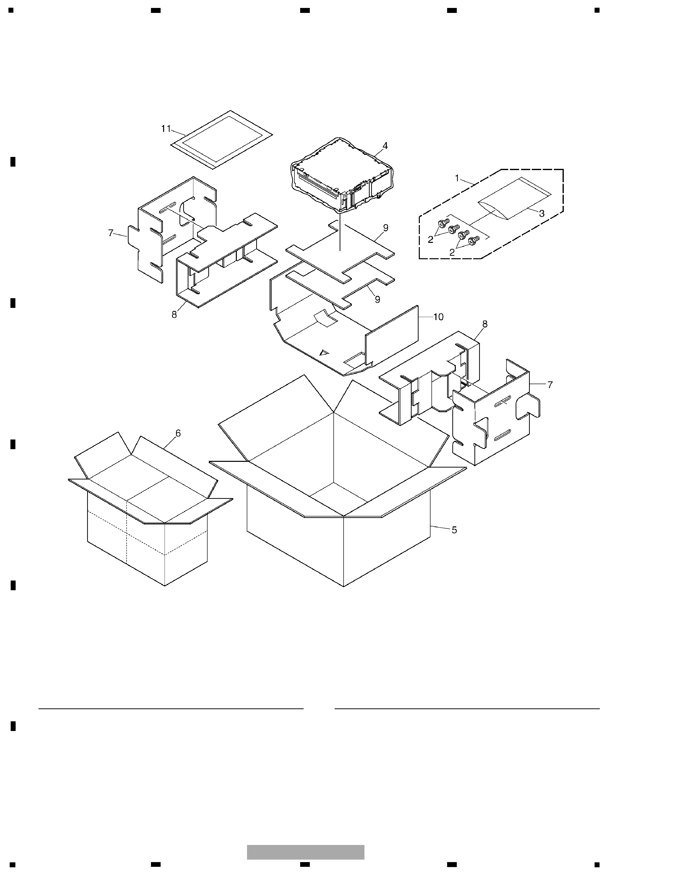
2. EXPLODED VIEWS AND PARTS LIST
2.1 PACKING
NOTE:
- Parts marked by "*" are generally unavailable because they are not in our Master Spare Parts List.
- Screws adjacent to
mark on the product are used for disassembly.
- For the applying amount of lubricants or glue, follow the instructions in this manual.
( In the case of no amount instructions, apply as you think it appropriate.)
1 Screw Assy
CEA3384
2 Screw(M5x0.8)
CBA1603
*
3 Polyethylene Bag
CEG1158
4 Polyethylene Bag
CEG1185
5 Carton
CHG4799
6 Contain Box
CHL4799
7 Protector
CHP2601
8 Protector
CHP2602
9 Protector
CHP2603
10 Protector
CHP2624
11-1 Polyethylene Bag
CEG1116
* 11-2 Warranty Card
CRY1203
Mark No. Description
Part No.
Mark No. Description
Part No.
- PACKING SECTION PARTS LIST
5
5
6
7
8
F
E
D
C
B
A
5
6
7
8
CDS-4027ZM/E
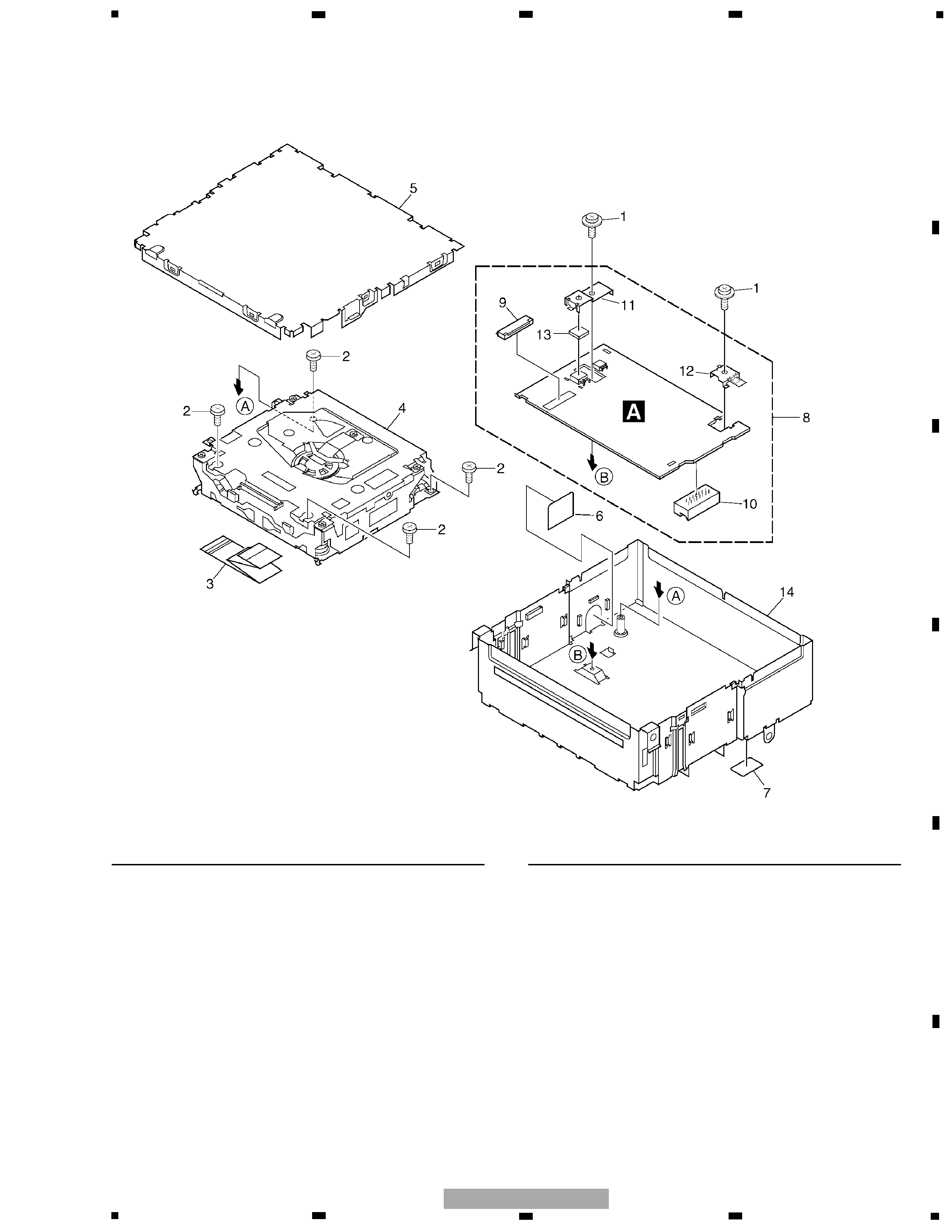
1 Screw
ASZ26P055FUC
2 Screw
BSZ26P060FMC
3 Connector
CDE7016
4 CD Mechanism Module(S9MP3)CXK5537
5 Case
CNB2763
6 Cover
CNM7850
7 Sheet
CNM7915
8 Extension Unit
CWM8362
9 Connector(CN351)
CKS1959
10 Plug(CN251)
CKS4583
11 Holder
CND1047
12 Holder
CND1048
13 Sheet
CNM7879
14 Chassis Unit
CXB8912
Mark No. Description
Part No.
Mark No. Description
Part No.
- EXTERIOR SECTION PARTS LIST
2.2 EXTERIOR