ORDER NO.
PIONEER CORPORATION 4-1, Meguro 1-chome, Meguro-ku, Tokyo 153-8654, Japan
PIONEER ELECTRONICS SERVICE, INC. P.O. Box 1760, Long Beach, CA 90801-1760, U.S.A.
PIONEER EUROPE NV Haven 1087, Keetberglaan 1, 9120 Melsele, Belgium
PIONEER ELECTRONICS ASIACENTRE PTE. LTD. 253 Alexandra Road, #04-01, Singapore 159936
PIONEER CORPORATION 2000
COMPACT DISC PLAYER
RRV2324
TZZY JUNE 2000 Printed in Japan
CDJ-500S
THIS MANUAL IS APPLICABLE TO THE FOLLOWING MODEL(S) AND TYPE(S).
¶ This service manual should be used together with the following manual(s):
Model No.
Order No.
Remarks
CDJ-500S/HY
RRV1846
Power Requirement
Type
Model
CDJ-500S
NK
O
AC220V
Remarks
CDJ-500S
2
1. CONTRAST OF MISCELLANEOUS PARTS
Parts marked by "NSP" are generally unavailable because they are not in our Master Spare Parts List.
The
mark found on some component parts indicates the importance of the safety factor of the part.
Therefore, when replacing, be sure to use parts of identical designation.
Screws adjacent to
mark on product are used for disassembly.
Reference Nos. indicate the pages and Nos. in the service manual for the base model.
NOTES:
When ordering resistors, first convert resistance values into code form as shown in the following examples.
Ex.1 When there are 2 effective digits (any digit apart from 0), such as 560 ohm and 47k ohm (tolerance is shown by J=5%,
and K=10%).
Ex.2 When there are 3 effective digits (such as in high precision metal film resistors).
561
473
R50
1R0
5621
560
47k
0.5
1
RD1/4PU
J
RD1/4PU
J
RN2H
K
RS1P
K
56 x 101
47 x 103
R50
1R0
561
473
5.62k
RN1/4PC
F
562 x 101
5621
CONTRAST TABLE
CDJ-500S/NK and CDJ-500S/HY are constructed the same except for the following :
PACKING
P4 - 4
Operating Instructions
DRB1214
Not used
(English/ French/ German/ Italian/ Dutch/ Spanish)
P4 - 4
Operating Instructions (English)
Not used
DRB1292
P4 - 9
Packing Case
DHG1785
DHG1784
EXTERIOR SECTION
P7 - 9
NSP
POWER SW BOARD ASSY
DWS1287
DWS1286
*1
P7 - 11
Cord Stopper
CM-22B
CM-22C
P7 - 20
Power Transformer (AC220- 230V/240V)
DTT1146
Not used
P7 - 20
Power Transformer (AC110/120V/220- 230V/240V)
Not used
DTT1143
*2
P7 - 21
AC Power Cord
PDG1003
DDG1082
P7 - 37
NSP
Rear Panel
DNC1460
DNC1530
P7 - 105
NSP
Caution Label
VRW1297
Not used
P7 - 106
Caution Label
VRW1094
Not used
Part No.
CDJ-500S/
HY
Ref. No.
Symbol and Description
Remarks
Mark
CDJ-500S/
NK
POWER SW BOARD ASSY
F
H
DWS1286 and DWS1287 are constructed the same except for the following :
Mark
Symbol and Description
Part No.
DWS1287
DWS1286
Remarks
NSP
J5 (Board in jumper wire)
Not used
DB110NB2
*1
NSP
J6 (Board in jumper wire)
Not used
DB810NB2
*1
S2 (Voltage selector sw)
DSB1011
DSB1014
*1
*1 : Refer to "2. SCHEMATIC DIAGRAM (2.1 POWER SW BOARD ASSY)".
*1 : For PCB ASSEMBLIES, Refer to "CONTRAST OF PCB ASSEMBLIES" and "2. SCHEMATIC DIAGRAM".
*2 : The voltage selector switch is fixed to AC220-230V.
CONTRAST OF PCB ASSEMBLIES
CDJ-500S
3
A
B
C
D
1
23
4
1
2
3
4
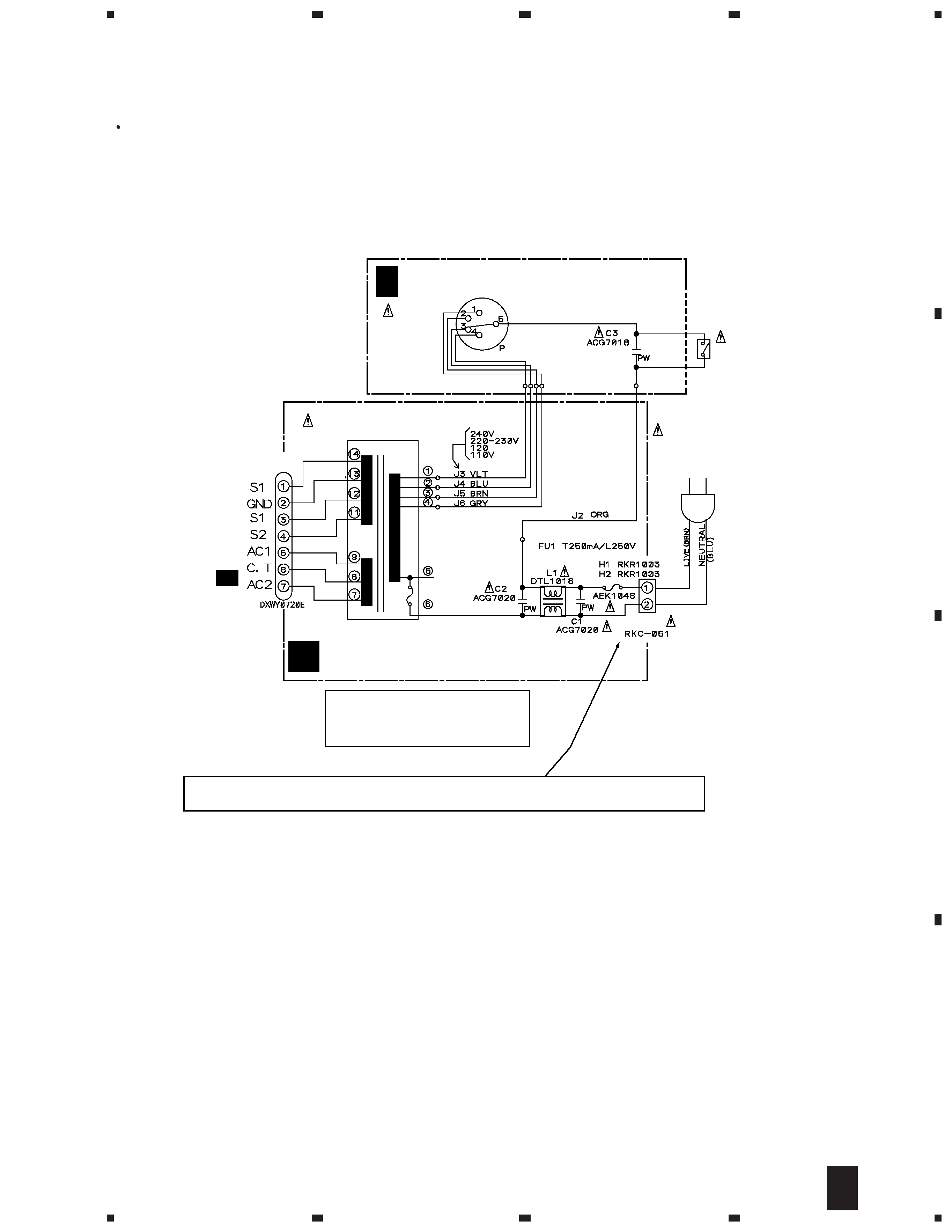
2. SCHEMATIC DIAGRAM
2.1 POWER SW BOARD ASSY
Only the differences in the schematic diagram between CDJ-500S/NK and CDJ-500S/HY are shown below.
CN1
H F
· NOTE FOR FUSE REPLACEMENT
FOR CONTINUED PROTECTION AGAINST RISK OF FIRE.
REPLACE WITH SAME TYPE AND RATINGS ONLY.
CAUTION -
POWER SW BOARD ASSY
(DWS1286)
I
TRANS BOARD ASSY
(DWR1286)
AC POWER CORD
DDG1082
AC220V
50/60Hz
POWER TRANSFORMER
DTT1143
CAPACITOR
COVER
DEC1241
S2
VOLTAGE
SELECTOR
DSB1014
BOARD IN JUMPER
S1
SWITCH
DSA1024
A
4/4
CN11
(10000p/AC250)
(4700p/AC250)
(10000p/AC250)
J2 (ORG): DDF1012
J3 (VLT): DB710NB2
J4 (BLU) : DB610NB2
J5 (BRN): DB110NB2
J6 (GRY): DB810NB2
J1
The voltage selector switch is fixed to thirdly.
F
H