
CONTENTS
1. SAFETY INFORMATION............................................2
2. EXPLODED VIEWS AND PARTS LIST ......................2
3. SCHEMATIC DIAGRAM .............................................4
4. PCB CONNECTION DIAGRAM..................................5
5. ELECTRICAL PARTS LIST..........................................6
6. ADJUSTMENT ...........................................................6
7. GENERAL INFORMATION.........................................7
7.1 IC ..........................................................................7
8. OPERATIONS AND SPECIFICATIONS ......................8
PIONEER ELECTRONIC CORPORATION
4-1, Meguro 1-Chome, Meguro-ku, Tokyo 153-8654, Japan
PIONEER ELECTRONICS SERVICE INC.
P.O.Box 1760, Long Beach, CA 90801-1760 U.S.A.
PIONEER ELECTRONIC [EUROPE] N.V.
Haven 1087 Keetberglaan 1, 9120 Melsele, Belgium
PIONEER ELECTRONICS ASIACENTRE PTE.LTD. 253 Alexandra Road, #04-01, Singapore 159936
C PIONEER ELECTRONIC CORPORATION 1999
K-ZZB. MAR. 1999 Printed in Japan
ORDER NO.
CRT2331
WIRELESS CELLULAR MUTE KIT
CD-CM1
E
Service
Manual
NOTE:
- For the detection diode (D401: HSM276SR), the withstanding static voltage is very low. So, pay special
attention to static electricity to protect the diode from electrostatic damage when servicing.
- When the detection antenna has been removed from the upper case for servicing, be sure to stick it
onto the upper case with adhesive tape along the guide, after the repair is completed.
2
CD-CM1
1. SAFETY INFORMATION
CAUTION
This service manual is intended for qualified service technicians; it is not meant for the casual do-it-yourselfer.
Qualified technicians have the necessary test equipment and tools, and have been trained to properly and safely repair
complex products such as those covered by this manual.
Improperly performed repairs can adversely affect the safety and reliability of the product and may void the warranty.
If you are not qualified to perform the repair of this product properly and safely; you should not risk trying to do so
and refer the repair to a qualified service technician.
WARNING
This product contains lead in solder and certain electrical parts contain chemicals which are known to the state of
California to cause cancer, birth defects or other reproductive harm.
Health & Safety Code Section 25249.6 - Proposition 65
NOTE:
- Screws adjacent to
mark on the product are used for disassembly.
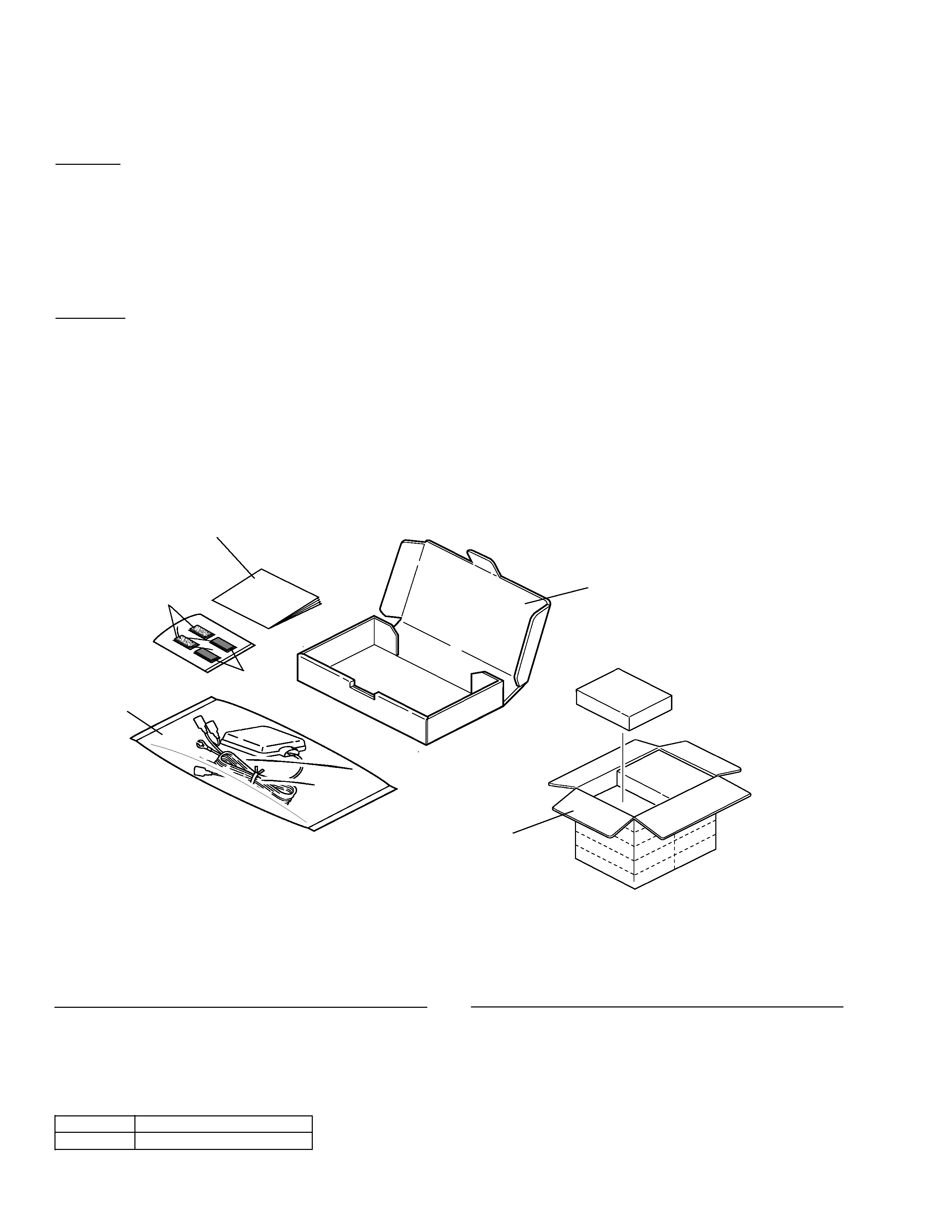
1 Polyethylene Bag
CEG1259
2 Carton
CHA2780
3 Contain Box
CHD2780
4 Fastener(rough)
CNM3709
5 Fastener(soft)
CNM3710
6 Owner's Manual
CRD3031
- PACKING SECTION PARTS LIST
Mark No. Description
Part No.
Mark No. Description
Part No.
2. EXPLODED VIEWS AND PARTS LIST
2.1 PACKING
1
5
4
6
2
3
- Owner's Manual
Part No.
Language
CRD3031
English,Spanish,French
3
CD-CM1
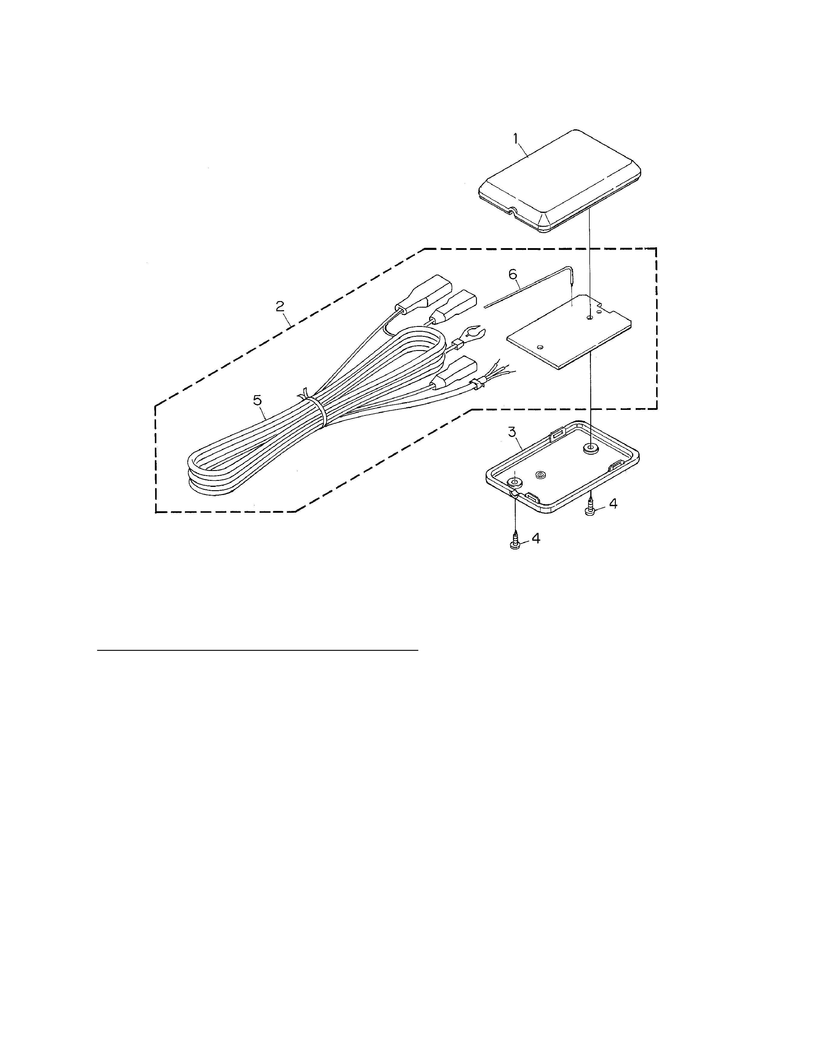
2.2 EXTERIOR
1 Case
CNS5425
2 Cellular Mute Unit
CWX2357
3 Case
CNS5426
4 Screw
BPZ20P080FZK
5 Cord
CDE5916
6 Cord
CDC1041
- EXTERIOR SECTION PARTS LIST
Mark No. Description
Part No.
4
CD-CM1
A
1
234
B
C
D
12
34
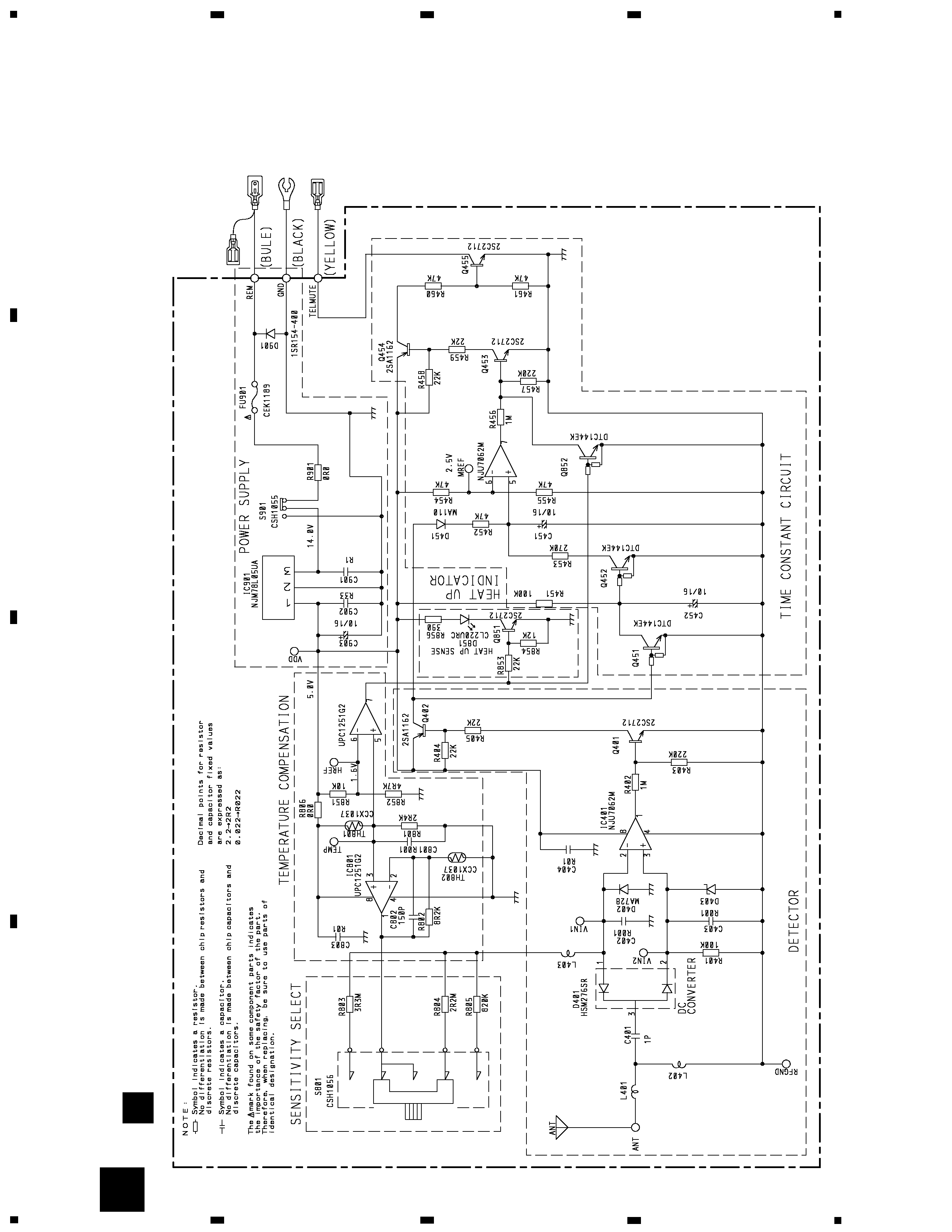
3. SCHEMATIC DIAGRAM
3.1 CELLULAR MUTE UNIT
Note: When ordering service parts, be sure to refer to "EXPLODED VIEWS AND PARTS LIST" or "ELECTRICAL PARTS
LIST".
A
MA8033(H)
(1/2)
(2/2)
(2/2)
(1/2)
200mA
A
CELLULAR
MUTE
UNIT
5
CD-CM1
1
2
3
4
A
B
C
D
1
2
3
4
A
CELLULAR MUTE UNIT
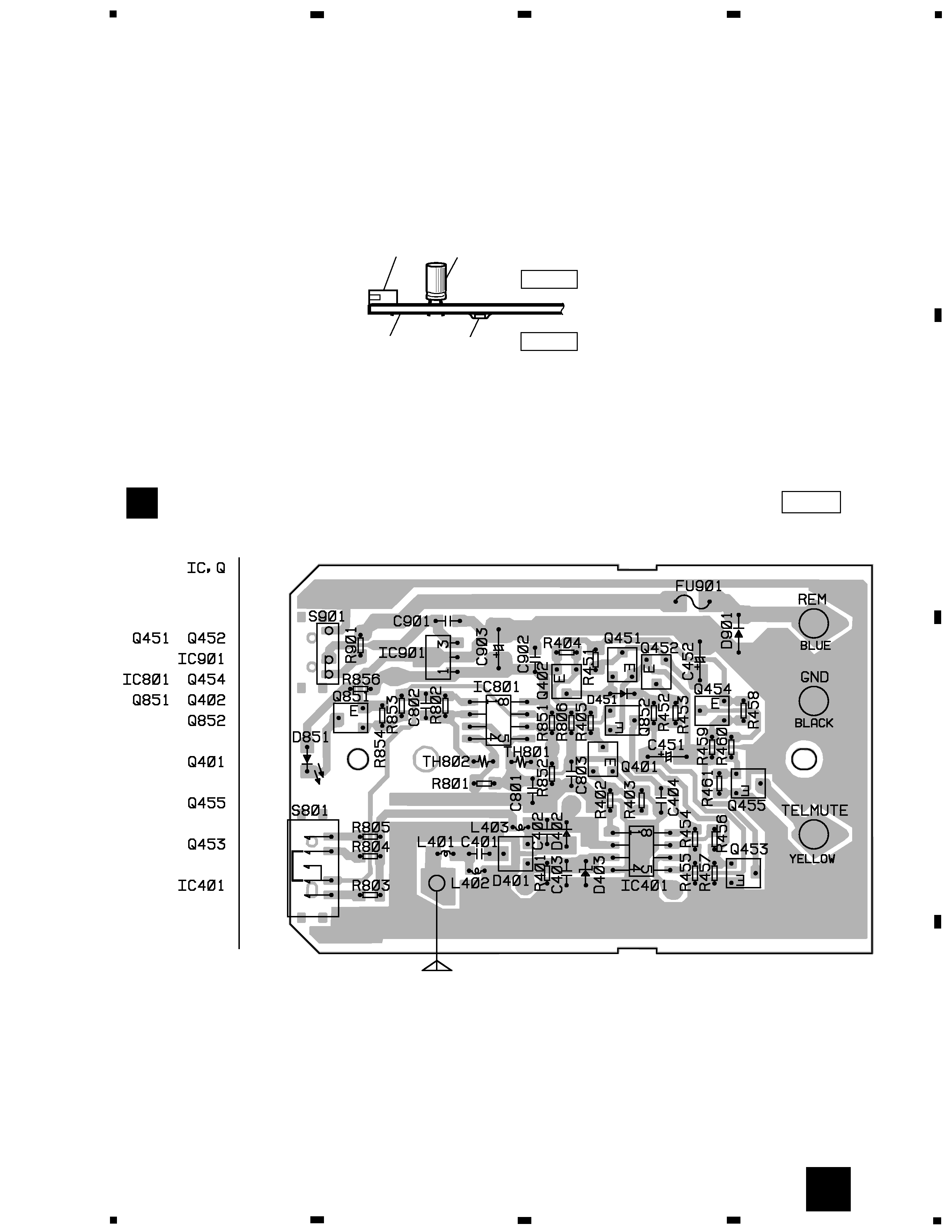
4. PCB CONNECTION DIAGRAM
4.1 CELLULAR MUTE UNIT
NOTE FOR PCB DIAGRAMS
1. The parts mounted on this PCB
include all necessary parts for
several destination.
For further information for
respective destinations, be sure
to check with the schematic
diagram.
2. Viewpoint of PCB diagrams
Capacitor
Connector
P.C.Board
Chip Part
SIDE A
SIDE B
A
SIDE A
ANTENNA
2. Viewpoint of PCB diagrams