ORDER NO.
BA-V2321C
CATV CONVERTER
ORDER NO.
ARP3025
O- SZS MAR. 1999 Printed in Japan
c
PIONEER ELECTRONIC CORPORATION 4-1, Meguro 1-Chome, Meguro-ku, Tokyo 153-8654, Japan
PIONEER ELECTRONICS SERVICE, INC. P.O. Box 1760, Long Beach, CA 90801-1760, U.S.A.
PIONEER ELECTRONIC (EUROPE) N.V. Haven 1087, Keetberglaan 1, 9120 Melsele, Belgium
PIONEER ELECTRONICS ASIACENTRE PTE. LTD. 253 Alexandra Road, #04-01, Singapore 159936
PIONEER ELECTRONIC CORPORATION 1999
Type
Model
Power Requirement
Remarks
BA-V2321C
KU
AC120V
THIS MANUAL IS APPLICABLE TO THE FOLLOWING MODEL(S) AND TYPE(S).
1. SAFETY INFORMATION ........................................... 2
2. EXPLODED VIEWS AND PARTS LIST ..................... 3
3. BLOCK DIAGRAM AND SCHEMATIC DIAGRAM ..... 6
4. PCB CONNECTION DIAGRAM ............................... 20
5. PCB PARTS LIST .................................................... 27
6. ADJUSTMENT ......................................................... 31
7. GENERAL INFORMATION ..................................... 36
7.1 IC ...................................................................... 36
8. PANEL FACILITIES AND SPECIFICATIONS ......... 43
CONTENTS
wink
Entertainer
PM
TIMER
A/B
MESSAGE
ADVANCED ANALOG TERMINAL
POWER
EXIT
SELECT
MENU
CH
VOL
+
VOL
CH
BA-V2321C
2
1. SAFETY INFORMATION
This service manual is intended for qualified service technicians; it is not meant for the casual
do-it-yourselfer. Qualified technicians have the necessary test equipment and tools, and have been
trained to properly and safely repair complex products such as those covered by this manual.
Improperly performed repairs can adversely affect the safety and reliability of the product and may
void the warranty. If you are not qualified to perform the repair of this product properly and safely, you
should not risk trying to do so and refer the repair to a qualified service technician.
WARNING
This product contains lead in solder and cer tain electrical par ts contain chemicals which are known to the state of
California to cause cancer, bir th defects or other reproductive harm.
Health & safety code section 25249.6--Proposition 65
NOTICE
(FOR CANADIAN MODEL ONLY)
Fuse symbols
(fast operating fuse)
and/or
(slow operating fuse) on PCB indicate that replacement
parts must be of identical designation.
REMARQUE
(POUR MODÈLE CANADIEN SEULEMENT)
Les symboles de fusible
(fusible de type rapide)
et/ou
(fusible de type lent) sur CCI indiquent que
les pièces de remplacement doivent avoir la même désignation.
ANY MEASUREMENTS NOT WITHIN THE
LIMITS OUTLINED ABOVE ARE INDICATIVE
OF A POTENTIAL SHOCK HAZARD AND
MUST BE CORRECTED BEFORE RETURN-
ING THE APPLIANCE TO THE CUSTOMER.
2. PRODUCT SAFETY NOTICE
Many electrical and mechanical parts in the appliance
have special safety related characteristics. These are
often not evident
from visual
inspection nor the
protection afforded by them necessarily can be obtained
by using replacement components rated for voltage,
wattage, etc. Replacement parts which have these
special safety characteristics are identified in this
Service Manual.
Electrical components having such features are
identified by marking with a
!
on the schematics and
on the parts list in this Service Manual.
The use of a substitute replacement component which
does not have the same safety characteristics as the
PIONEER recommended replacement one, shown in the
parts list in this Service Manual, may create shock, fire,
or other hazards.
Product Safety is continuously under review and new
instructions are issued from time to time. For the latest
information, always consult the current PIONEER
Ser vice Manual. A subscription to, or additional copies
of, PIONEER Service Manual may be obtained at a
nominal charge from PIONEER.
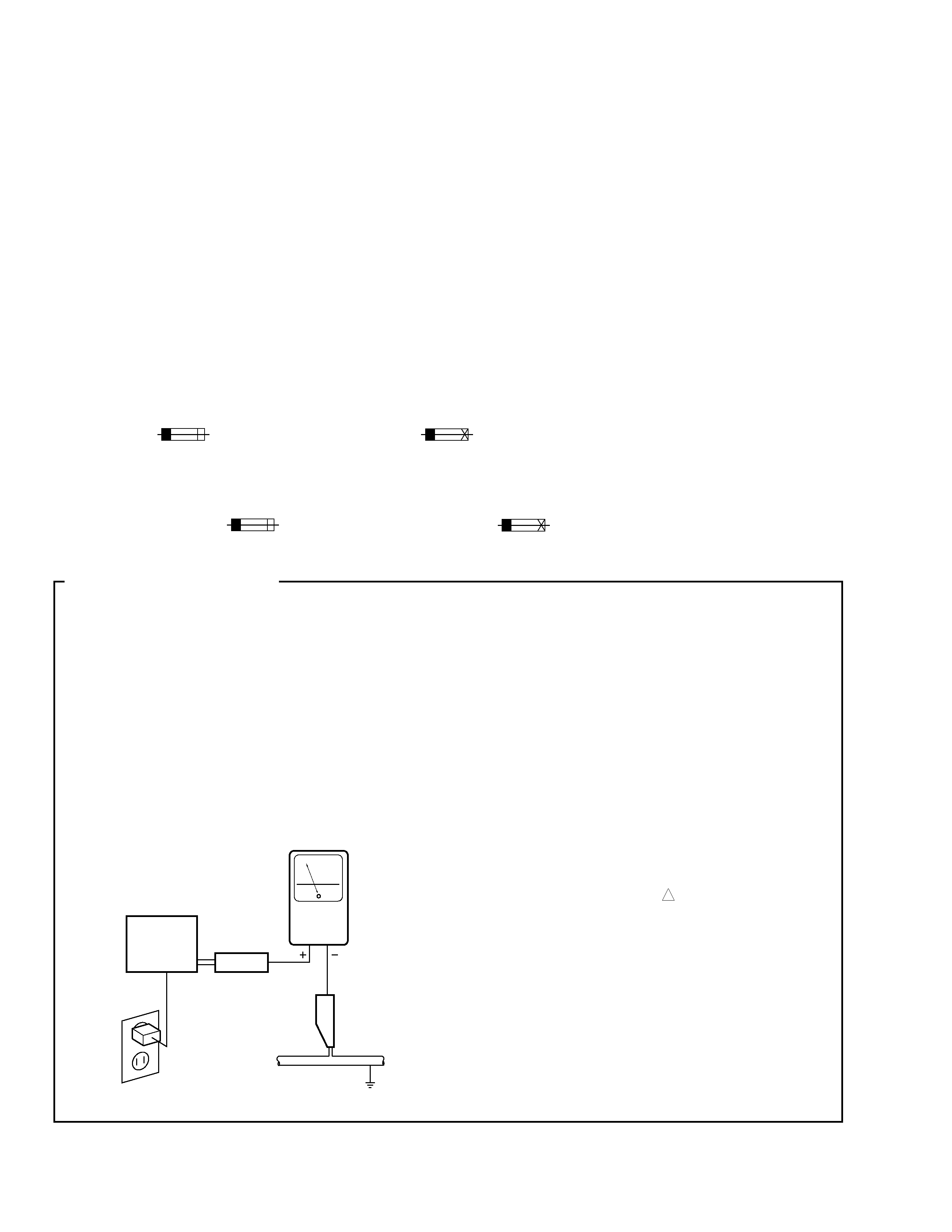
(FOR USA MODEL ONLY)
1. SAFETY PRECAUTIONS
The following check should be performed for the
continued protection of the customer and service
technician.
LEAKAGE CURRENT CHECK
Measure leakage current to a known earth ground
(water pipe, conduit, etc.) by connecting a leakage
current tester such as Simpson Model 229-2 or
equivalent between the earth ground and all exposed
metal parts of the appliance (input/output terminals,
screwheads, metal overlays, control shaft, etc.). Plug
the AC line cord of the appliance directly into a 120V
AC 60 Hz outlet and turn the AC power switch on. Any
current measured must not exceed 0.5 mA.
Device
under
test
Leakage
current
tester
Earth
ground
Reading should
not be above
0.5 mA
Also test with
plug reversed
(Using AC adapter
plug as required)
Test all
exposed metal
surfaces
AC Leakage Test
3
BA-V2321C
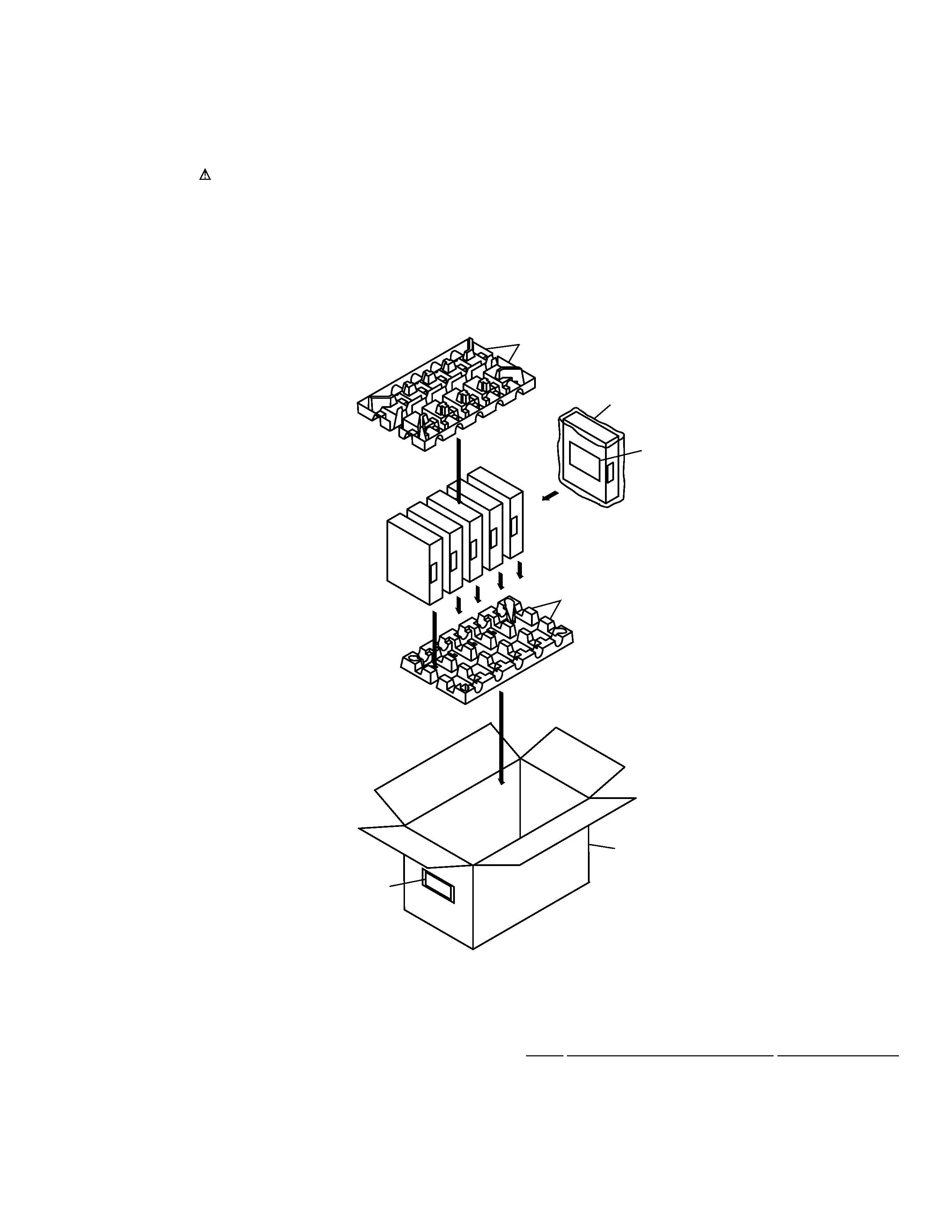
2.1 PACKING
NSP
1
BAR CORD LABEL
BAL1332
2
PACKING CASE
BHD1416
3
PULP MOLD
BHX1009
4
PLASTIC BAG
BHG1021
5
INSTRUCTION MANUAL
BRB1053
(ENGLISH)
· PACKING PARTS LIST
Mark No.
Description
Part No.
2. EXPLODED VIEWS AND PARTS LIST
NOTES:
·Parts marked by "NSP" are generally unavailable because they are not in our Master Spare Parts List.
·The mark found on some component parts indicates the importance of the safety factor of the part.
Therefore, when replacing, be sure to use parts of identical designation.
FRONT
3
3
4
5
2
1
TO
P
4
BA-V2321C
25
26
1
22
6
9
22
28
27
1
LED ASSY
BWX1114
2
MAIN ASSY
BWX1111
3
SW POWER SUPPLY
BXF1088
4
ZENITH DSCR ASSY
BWX1081
5
AC POWER CORD
BDG1039
6
FLEXIBLE CABLE
BDD1026
7
CHASSIS
BNA1145
8
PROTECTION COVER
BNG1184
9
GROUND PLATE
BNK1099
NSP
10
PCB HOLDER
AEC1088
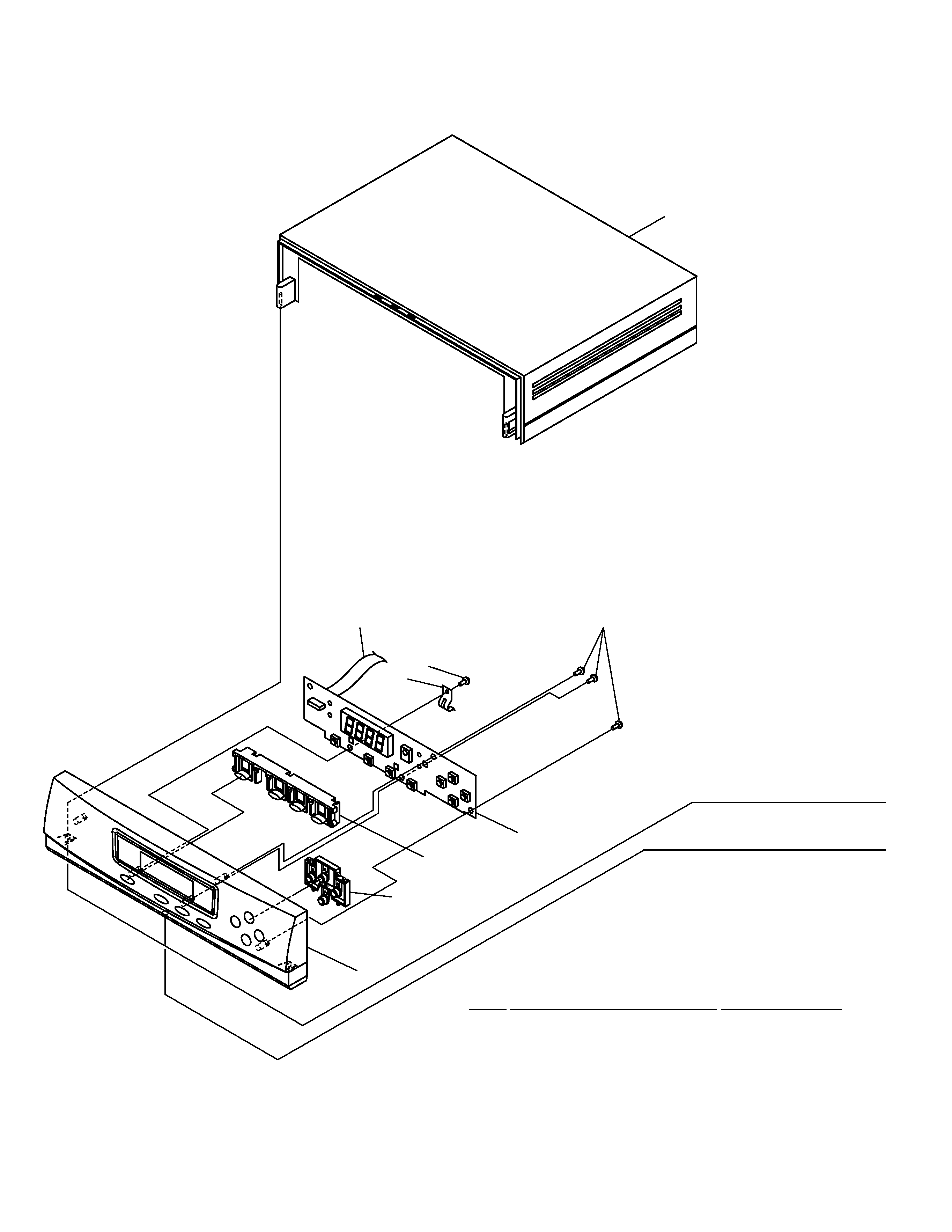
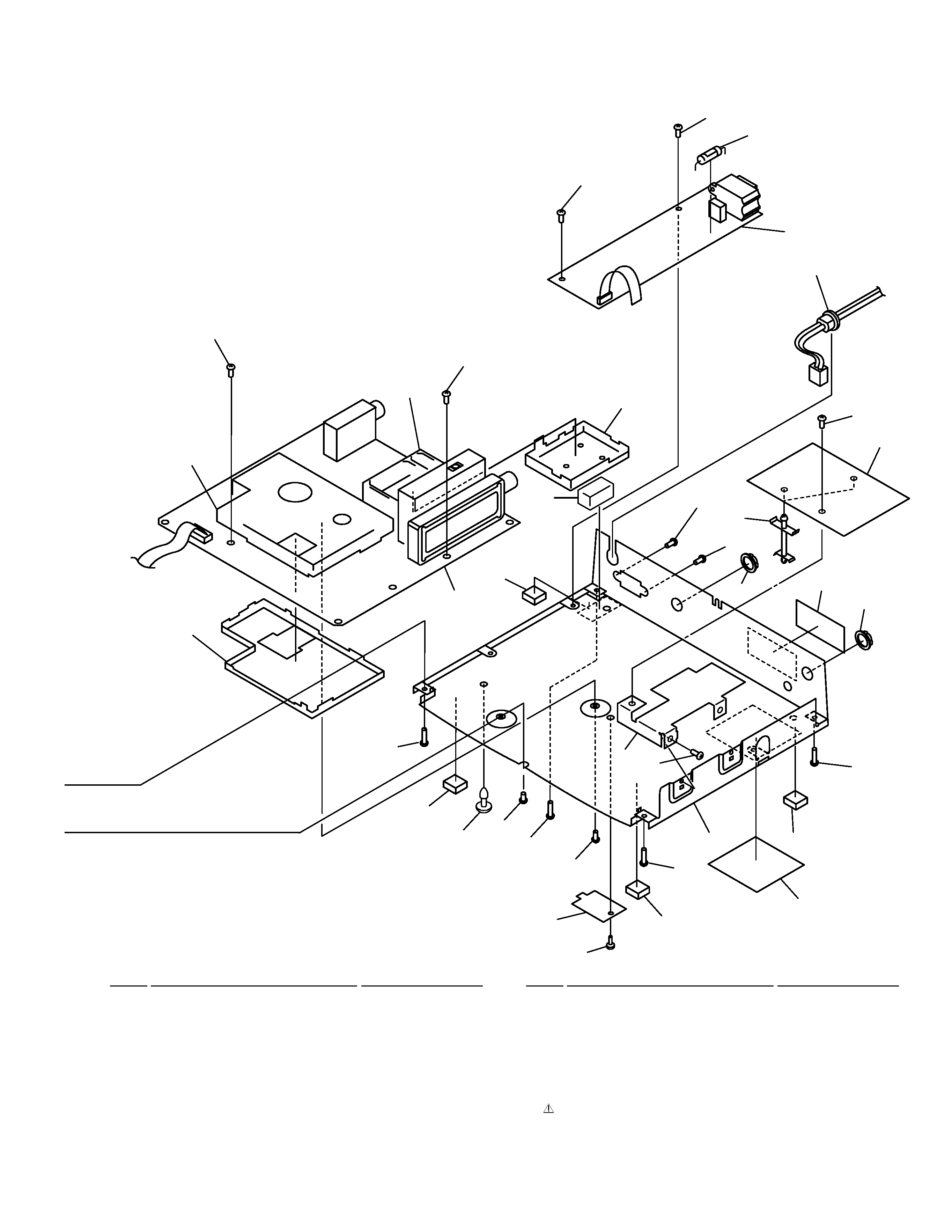
7 EXTERIOR PARTS LIST
Mark No.
Description
Part No.
2.2 EXTERIOR
5
BA-V2321C
11
FOOT CLOTH
BEB1032
12
ANCHOR CLIP
BEC1022
NSP
13
BAR CORD LABEL
BAL1331
NSP
14
NAME PLATE
BAL1334
15
SCREW (STEEL)
BBA1020
16
WASHER FACED NUT
BBN1005
17
PCB HOLDER
BNG1321
18
PCB SPACER
AEC1100
19
CUSHION RUBBER
BEB1088
20
SCREW
BBZ30P060FMC
21
SCREW
BBZ30P080FMC
22
SCREW
BPZ26P080FMC
23
SCREW
CPZ30P080FZK
24
SCREW
VPZ30P140FMC
25
FRONT PANEL
BMB1075
26
STATION BUTTON A
BAD1107
27
STATION BUTTON B
BAD1108
28
PLASTIC CABINET
BME1025
29
FUSE ASSY
BZE2023
NSP
30
CPU SHIELD CASE
BNK1109
NSP
31
CPU SHIELD COVER
BNK1110
NSP
32
FSK SHIELD CASE
BNK1111
NSP
33
FSK SHIELD COVER
BNK1112
Mark No.
Description
Part No.
Mark No.
Description
Part No.
20
20
20
3
5
21
21
16
7
16
13
20
2
11
24
11
24
23
15
8
12
11
24
11
24
30
32
31
33
19
29
14
10
20
4
18
20
17