ORDER NO.
PIONEER CORPORATION 4-1, Meguro 1-chome, Meguro-ku, Tokyo 153-8654, Japan
PIONEER ELECTRONICS (USA) INC. P.O. Box 1760, Long Beach, CA 90801-1760, U.S.A.
PIONEER EUROPE NV Haven 1087, Keetberglaan 1, 9120 Melsele, Belgium
PIONEER ELECTRONICS ASIACENTRE PTE. LTD. 253 Alexandra Road, #04-01, Singapore 159936
PIONEER CORPORATION 2002
AVX-MG2027ZF/XN/UC
CRT2871
RECEIVER ASSY WITH NAVIGATION DISPLAY
AVX-MG2027ZF
XN/UC
RECEIVER ASSY WITH NAVIGATION DISPLAY
AVX-MG2127ZF
XN/UC
RECEIVER ASSY WITH NAVIGATION DISPLAY
AVX-MG2227ZF
XN/UC
RECEIVER ASSY WITH NAVIGATION DISPLAY
AVX-MG2327ZF
XN/UC
This service manual should be used together with the following manual(s):
Model No.
Order No.
Mech.Module
Remarks
CX-951
CRT2872
G2
CD Mech. module:Circuit Description, Mech.Description, Disassembly
For details, refer to "Important symbols for good services".
K-ZZD.SEPT. 2002.printed in Japan
FORD
AVX-MG2027ZF/XN/UC
A
B
C
D
12
34
12
3
4
2
-
-
-
- CD Player Service Precautions
1. Before disassembling the unit, be sure to turn off the power. Unplugging and plugging the con-
nectors during power-on mode may damage the ICs inside the unit.
2. To protect the pickup unit from electrostatic discharge during servicing, take an appropriate
treatment shorting-solder by referring to "the DISASSEMBLY" on page 116.
3. After replacing the pickup unit, be sure to check the grating. (See p.105.)
VEHICLE
PRODUCED
AFTER
OEM PARTS No.
ID No.
PIONEER MODEL No.
LINCOLN LS
November 2002
3W4T-18K931-A1
·····
AVX-MG2027ZF/XN/UC
LINCOLN TOWNCAR
December 2002
3W1T-18C985-AF
·····
AVX-MG2127ZF/XN/UC
LINCOLN NAVIGATOR
February 2003
3L7T-18C985-AD
·····
AVX-MG2227ZF/XN/UC
LINCOLN AVIATOR
October 2002
3C5T-18C985
·····
AVX-MG2327ZF/XN/UC
AVX-MG2027ZF/XN/UC
A
B
C
D
56
7
8
56
7
8
3
SAFETY INFORMATION
This service manual is intended for qualified service technicians; it is not meant for the casual do-it-yourselfer.
Qualified technicians have the necessary test equipment and tools, and have been trained to properly and safely repair
complex products such as those covered by this manual.
Improperly performed repairs can adversely affect the safety and reliability of the product and may void the warranty.
If you are not qualified to perform the repair of this product properly and safely, you should not risk trying to do so
and refer the repair to a qualified service technician.
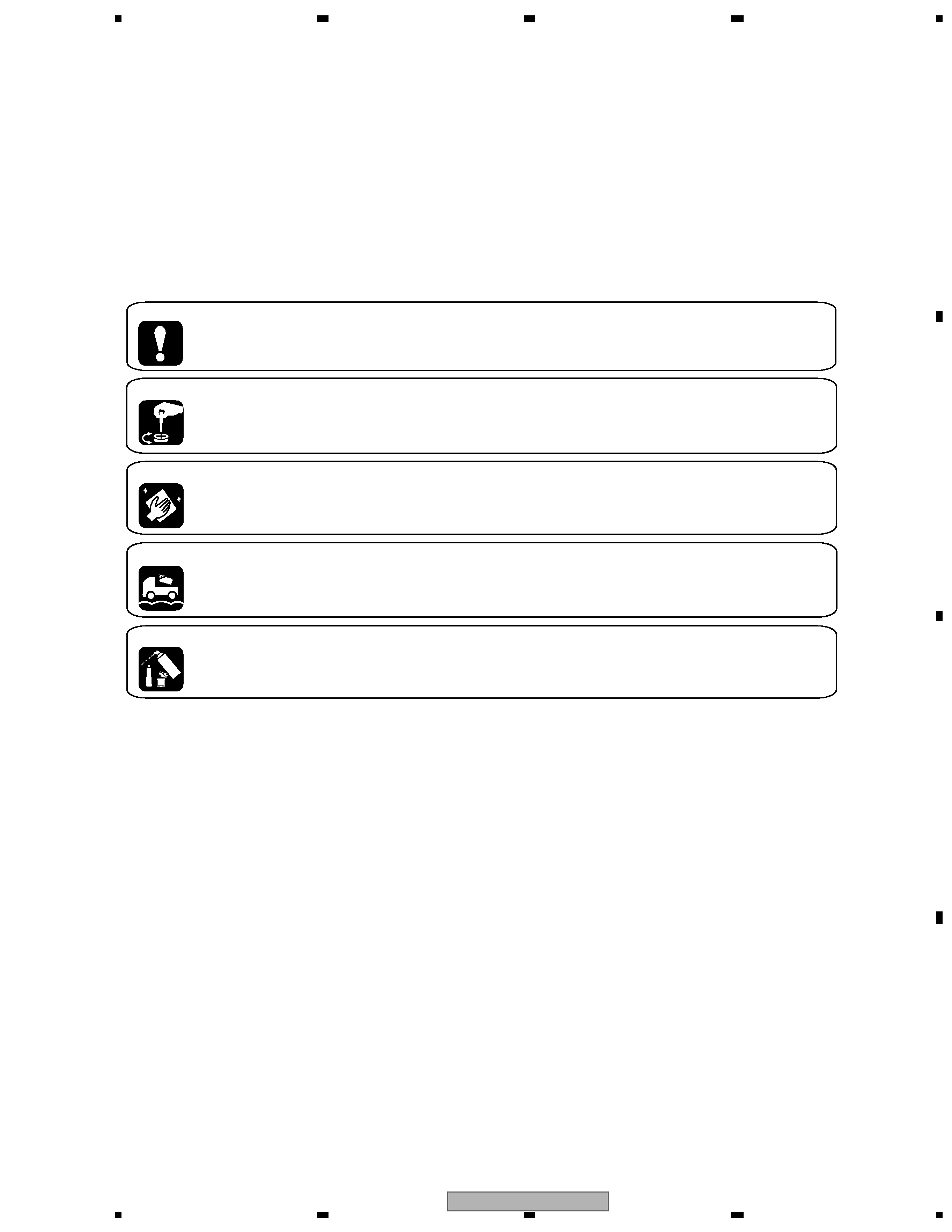
[ Important symbols for good services ]
In this manual, the symbols shown-below indicate that adjustments, settings or cleaning should be made securely.
When you find the procedures bearing any of the symbols, be sure to fulfill them:
2. Adjustments
To keep the original performances of the product, optimum adjustments or specification confirmation is indispensable.
In accordance with the procedures or instructions described in this manual, adjustments should be performed.
3. Cleaning
For optical pickups, tape-deck heads, lenses and mirrors used in projection monitors, and other parts requiring cleaning,
proper cleaning should be performed to restore their performances.
5. Lubricants, glues, and replacement parts
Appropriately applying grease or glue can maintain the product performances. But improper lubrication or applying
glue may lead to failures or troubles in the product. By following the instructions in this manual, be sure to apply the
prescribed grease or glue to proper portions by the appropriate amount.For replacement parts or tools, the prescribed
ones should be used.
4. Shipping mode and shipping screws
To protect the product from damages or failures that may be caused during transit, the shipping mode should be set or
the shipping screws should be installed before shipping out in accordance with this manual, if necessary.
1. Product safety
You should conform to the regulations governing the product (safety, radio and noise, and other regulations), and
should keep the safety during servicing by following the safety instructions described in this manual.

AVX-MG2027ZF/XN/UC
A
B
C
D
12
34
12
3
4
4
CONTENTS
SAFETY INFORMATION . . . . . . . . . . . . . . . . . . . . . . . . . . . . . . . . . . . . . . . . . . . . . 3
1. SPECIFICATIONS . . . . . . . . . . . . . . . . . . . . . . . . . . . . . . . . . . . . . . . . . . . . . . . 5
2. EXPLODED VIEWS AND PARTS LIST . . . . . . . . . . . . . . . . . . . . . . . . . . . . . . . . . . . . 6
2.1 EXTERIOR(1)(AVX-MG2027ZF). . . . . . . . . . . . . . . . . . . . . . . . . . . . . . . . . . . . . . 6
2.2 EXTERIOR(1)(AVX-MG2127ZF). . . . . . . . . . . . . . . . . . . . . . . . . . . . . . . . . . . . . . 8
2.3 EXTERIOR(1)(AVX-MG2227ZF,AVX-MG2327ZF). . . . . . . . . . . . . . . . . . . . . . . . . . . . 10
2.4 EXTERIOR(2)(AVX-MG2027ZF,AVX-MG2127ZF). . . . . . . . . . . . . . . . . . . . . . . . . . . . 12
2.5 EXTERIOR(2)(AVX-MG2227ZF,AVX-MG2327ZF). . . . . . . . . . . . . . . . . . . . . . . . . . . . 14
2.6 CD MECHANISM UNIT(G2)(1) . . . . . . . . . . . . . . . . . . . . . . . . . . . . . . . . . . . . . 16
2.7 CD MECHANISM UNIT(G2)(2) . . . . . . . . . . . . . . . . . . . . . . . . . . . . . . . . . . . . . 18
3. BLOCK DIAGRAM AND SCHEMATIC DIAGRAM . . . . . . . . . . . . . . . . . . . . . . . . . . . . . . 20
3.1 BLOCK DIAGRAM(1) . . . . . . . . . . . . . . . . . . . . . . . . . . . . . . . . . . . . . . . . . . 20
3.2 BLOCK DIAGRAM(2) . . . . . . . . . . . . . . . . . . . . . . . . . . . . . . . . . . . . . . . . . . 22
3.3 OVERALL CONNECTION DIAGRAM . . . . . . . . . . . . . . . . . . . . . . . . . . . . . . . . . . 24
3.4 TUNER AUDIO UNIT(GUIDE PAGE) . . . . . . . . . . . . . . . . . . . . . . . . . . . . . . . . . . 26
3.5 DSP UNIT . . . . . . . . . . . . . . . . . . . . . . . . . . . . . . . . . . . . . . . . . . . . . . . . 32
3.6 MODULE UNIT . . . . . . . . . . . . . . . . . . . . . . . . . . . . . . . . . . . . . . . . . . . . . 34
3.7 TUNER PCB . . . . . . . . . . . . . . . . . . . . . . . . . . . . . . . . . . . . . . . . . . . . . . . 38
3.8 CONNECTOR PCB . . . . . . . . . . . . . . . . . . . . . . . . . . . . . . . . . . . . . . . . . . . 39
3.9 PANEL PCB UNIT . . . . . . . . . . . . . . . . . . . . . . . . . . . . . . . . . . . . . . . . . . . . 40
3.10 KEYBOARD UNIT . . . . . . . . . . . . . . . . . . . . . . . . . . . . . . . . . . . . . . . . . . . 41
3.11 CD MECHANISM MODULE(G2F)(GUIDE PAGE) . . . . . . . . . . . . . . . . . . . . . . . . . . . 42
4. PCB CONNECTION DIAGRAM . . . . . . . . . . . . . . . . . . . . . . . . . . . . . . . . . . . . . . . 52
4.1 TUNER AUDIO UNIT . . . . . . . . . . . . . . . . . . . . . . . . . . . . . . . . . . . . . . . . . . 52
4.2 MODULE UNIT . . . . . . . . . . . . . . . . . . . . . . . . . . . . . . . . . . . . . . . . . . . . . 56
4.3 DSP UNIT . . . . . . . . . . . . . . . . . . . . . . . . . . . . . . . . . . . . . . . . . . . . . . . . 60
4.4 TUNER PCB . . . . . . . . . . . . . . . . . . . . . . . . . . . . . . . . . . . . . . . . . . . . . . . 61
4.5 CONNECTOR PCB . . . . . . . . . . . . . . . . . . . . . . . . . . . . . . . . . . . . . . . . . . . 62
4.6 PANEL PCB UNIT . . . . . . . . . . . . . . . . . . . . . . . . . . . . . . . . . . . . . . . . . . . . 63
4.7 KEYBOARD UNIT . . . . . . . . . . . . . . . . . . . . . . . . . . . . . . . . . . . . . . . . . . . . 64
4.8 CONTROL UNIT(G2F). . . . . . . . . . . . . . . . . . . . . . . . . . . . . . . . . . . . . . . . . . 66
4.9 PCB UNIT(LED),PCB UNIT(SIDE) . . . . . . . . . . . . . . . . . . . . . . . . . . . . . . . . . . . 68
4.10 PCB UNIT(SIDE) . . . . . . . . . . . . . . . . . . . . . . . . . . . . . . . . . . . . . . . . . . . . 69
4.11 PCB UNIT . . . . . . . . . . . . . . . . . . . . . . . . . . . . . . . . . . . . . . . . . . . . . . . 70
4.12 PCB UNIT(M2 UNIT) . . . . . . . . . . . . . . . . . . . . . . . . . . . . . . . . . . . . . . . . . . 71
5. ELECTRICAL PARTS LIST . . . . . . . . . . . . . . . . . . . . . . . . . . . . . . . . . . . . . . . . . 72
6. ADJUSTMENT . . . . . . . . . . . . . . . . . . . . . . . . . . . . . . . . . . . . . . . . . . . . . . . 102
6.2 CD ADJUSTMENT. . . . . . . . . . . . . . . . . . . . . . . . . . . . . . . . . . . . . . . . . . . 103
6.3 CHECKING THE GRATING AFTER CHANGING THE PICKUP UNIT . . . . . . . . . . . . . . . . 105
6.4 TEST MODE . . . . . . . . . . . . . . . . . . . . . . . . . . . . . . . . . . . . . . . . . . . . . . 108
6.5 ERROR CODE LIST . . . . . . . . . . . . . . . . . . . . . . . . . . . . . . . . . . . . . . . . . . 108
6.6 MODULE UNIT ADJUSTMENT . . . . . . . . . . . . . . . . . . . . . . . . . . . . . . . . . . . . 113
7. GENERAL INFORMATION . . . . . . . . . . . . . . . . . . . . . . . . . . . . . . . . . . . . . . . . . 116
7.1 DIAGNOSIS . . . . . . . . . . . . . . . . . . . . . . . . . . . . . . . . . . . . . . . . . . . . . . 116
7.1.1 DISASSEMBLY . . . . . . . . . . . . . . . . . . . . . . . . . . . . . . . . . . . . . . . . . . . 116
7.1.2 PCB LOCATIONS . . . . . . . . . . . . . . . . . . . . . . . . . . . . . . . . . . . . . . . . . . 121
7.1.3 CONNECTOR FUNCTION DESCRIPTION . . . . . . . . . . . . . . . . . . . . . . . . . . . . . 122
7.2 IC . . . . . . . . . . . . . . . . . . . . . . . . . . . . . . . . . . . . . . . . . . . . . . . . . . . 123
7.3 EXPLANATION . . . . . . . . . . . . . . . . . . . . . . . . . . . . . . . . . . . . . . . . . . . . 133
7.3.1 OPERATIONAL FLOW CHART . . . . . . . . . . . . . . . . . . . . . . . . . . . . . . . . . . . 133
7.3.2 SYSTEM BLOCK DIAGRAM . . . . . . . . . . . . . . . . . . . . . . . . . . . . . . . . . . . . 134
7.4 NOTES ON SERVICING. . . . . . . . . . . . . . . . . . . . . . . . . . . . . . . . . . . . . . . . 135
7.4.1 CLEANING. . . . . . . . . . . . . . . . . . . . . . . . . . . . . . . . . . . . . . . . . . . . . . 135
7.4.2 FACTORY SETTINGS . . . . . . . . . . . . . . . . . . . . . . . . . . . . . . . . . . . . . . . . 135
8. OPERATIONS . . . . . . . . . . . . . . . . . . . . . . . . . . . . . . . . . . . . . . . . . . . . . . . 136

AVX-MG2027ZF/XN/UC
A
B
C
D
56
7
8
56
7
8
5
1. SPECIFICATIONS
General
Power source . . . . . . 14.4V(10.5V-16.0V allowable) DC
Grounding system . . . . . . . . . . . . . . Negative type
Backup current. . . . . . . . . . . . . . . . . 3mA or less
Dimensions(AVX-MG2027ZF) .246(W) x112(H) x188(D)mm
(AVX-MG2127ZF) 191(W) x109(H) x185(D)mm
(AVX-MG2227ZF) 201(W) x109(H) x183(D)mm
(AVX-MG2327ZF) 201(W) x109(H) x183(D)mm
Weight . . . . . . . . . . . . . . . . . . . . . . . . . 2.7kg
CD player
System. . . . . . . . . . . . . Compact disc audio system
Usable discs . . . . . . . . . . . . . . . . . Compact disc
Signal format. . . . . . . . . Sampling frequency : 44.1kHz
. . . . . . . . . . . . . . Number of quantization : 16;linear
S/N. . . . . . . . . . . . . . . . . . . . . . 75dB or more
Distortion . . . . . . . . . . . . . . . . . . . 0.1% or less
FM tuner
Frequency . . . . . . . . . . . . . 87.75, 87.9107.9 MHz
S/N. . . . . . . . . . . . . . . . . . . . . . 58dB or more
Distortion . . . . . . . . . . . . . . . . . . . 1.5% or less
IF interference . . . . . . . . . . . . . . . . 95dB or more
Image interference . . . . . . . . . . . . . . 45dB or more
Stereo Separation . . . . . . . . . . 25dB or more(400Hz)
AM tuner
Frequency . . . . . . . . . . . . . . . . . . 5301710 kHz
S/N 20dB usable sensibility . . . . . . . . . . 33dBµ ± 6dB
S/N. . . . . . . . . . . . . . . . . . . . 50dB +10dB, -6dB
Distortion . . . . . . . . . . . . . . . . . . . 1.0% or less
IF interference . . . . . . . . . . . . . . . . 75dB or more
Image interference . . . . . . . . . . . . . . 60dB or more
Display
Screen size/Aspect ratio . . . . . . . . . 6.5 inch wide/16:9
(effective display area) . . . . . . . . . . . 143.4 x 79.3 mm
Pixels . . . . . . . . . . . . . . . . . . 93,600(400 x 234)
Sub pixels . . . . . . . . . . . . . . .280,800(1200 x 234)
Type . . . . . . . . . . . . . . . . . . . TFT active matrix
Color system. . . . . . . . . . . . . . . NTSC compatible