AV SYSTEM MONITOR
AVX-505
UC
Service
Manual
PIONEER ELECTRONIC CORPORATION
4-1, Meguro 1-Chome, Meguro-ku, Tokyo 153-8654, Japan
PIONEER ELECTRONICS SERVICE INC.
P.O.Box 1760, Long Beach, CA 90801-1760 U.S.A.
PIONEER ELECTRONIC [EUROPE] N.V.
Haven 1087 Keetberglaan 1, 9120 Melsele, Belgium
PIONEER ELECTRONICS ASIACENTRE PTE.LTD. 501 Orchard Road, #10-00, Lane Wheelock Place, Singapore 23880
C PIONEER ELECTRONIC CORPORATION 1998
ORDER NO.
CRT2192
CONTENTS
1. SAFETY INFORMATION ............................................2
2. EXPLODED VIEWS AND PARTS LIST .......................2
3. SCHEMATIC DIAGRAM ...........................................10
4. PCB CONNECTION DIAGRAM ................................30
5. ELECTRICAL PARTS LIST ........................................42
6. ADJUSTMENT..........................................................49
7. GENERAL INFORMATION .......................................50
7.1 IC ........................................................................50
7.2 DIAGNOSIS ........................................................51
7.2.1 DISASSEMBLY...........................................51
7.2.2 TROUBLESHOOTING FOR
LCD 5.5 MONITOR ....................................58
7.3 EXPLANATION ...................................................68
7.3.1 MECHANISM DESCRIPTIONS ..................68
7.3.2 BLOCK DIAGRAM......................................70
8. OPERATIONS AND SPECIFICATIONS.....................71
K-FED. APR. 1998 Printed in Japan
- Precautions on Safety for Replacement of Backlight
· High voltage is generated in the inverter when the power is supplied to the system. To avoid an electric
shock, reconfirm that the power switch is set to OFF before starting operation.
· The fluorescent tube and high-voltage parts have high temperature immediately after the power
switch of the main unit is set to OFF. To avoid burning your hand or similar accidents, wait awhile after
turning the power to OFF, then start operation.
· High voltage may be charged to the inverter immediately after the power switch of the main unit is set
to OFF. Wait awhile after turning the power to OFF, then start operation.
· In some cases, the cold cathode tube of backlight may be damaged. Take adequate caution for injury
during operation.
2
AVX-505
2. EXPLODED VIEWS AND PARTS LIST
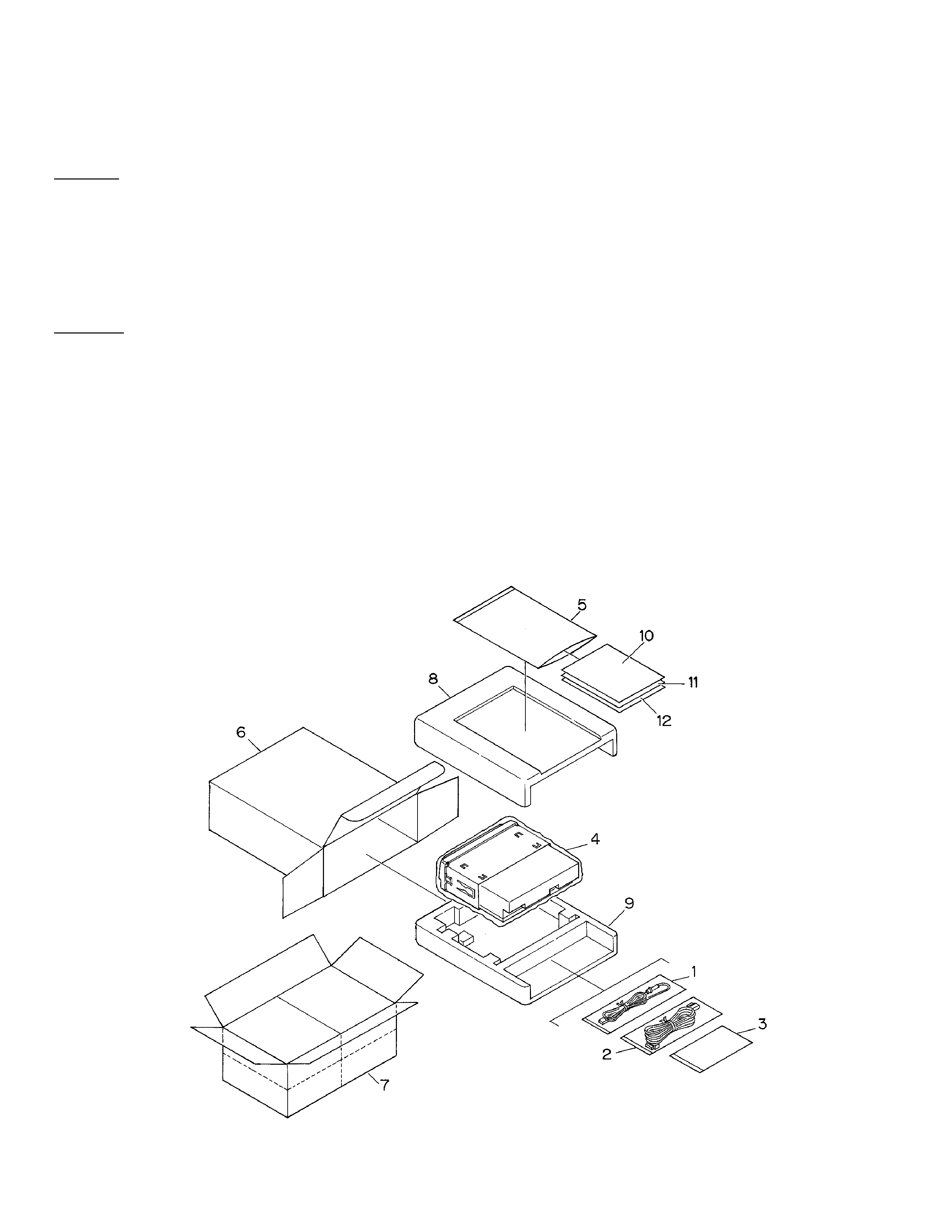
2.1 PACKING
CAUTION
This service manual is intended for qualified service technicians; it is not meant for the casual do-it-yourselfer.
Qualified technicians have the necessary test equipment and tools, and have been trained to properly and safely repair
complex products such as those covered by this manual.
Improperly performed repairs can adversely affect the safety and reliability of the product and may void the warranty.
If you are not qualified to perform the repair of this product properly and safely; you should not risk trying to do so
and refer the repair to a qualified service technician.
WARNING
Lead in solder used in this product is listed by the California Health and Welfare agency as a known reproductive
toxicant which may cause birth defects or other reproductive harm (California Health and Safety Code, Section
25249.5). When servicing or handling circuit boards and other components which contain lead in solder, avoid
unprotected skin contact with the solder. Also, when soldering do not inhale any smoke or fumes produced.
1. SAFETY INFORMATION

3
AVX-505
NOTE:
- Parts marked by "*"are generally unavailable because they are not in our Master Spare Parts List.
- Screws adjacent to
mark on the product are used for disassembly.
- Owner's Manual
Model
Part No.
Language
AVX-505/UC
CRD2679
English, French
1 Cord Assy
CDE5626
2 Cord Assy
CDE5716
3 Accessory Assy
CEA2467
4 Polyethylene Bag
CEG1173
5 Polyethylene Bag
CEG1116
6 Carton
CHG3507
7 Contain Box
CHL3507
8 Protector
CHP2040
9 Protector
CHP2041
*
10 Card
ARY1048
*
11 Warranty Card
Not used
12 Owner's Manual
CRD2679
- PACKING SECTION PARTS LIST
Mark No. Description
Part No.
4
AVX-505
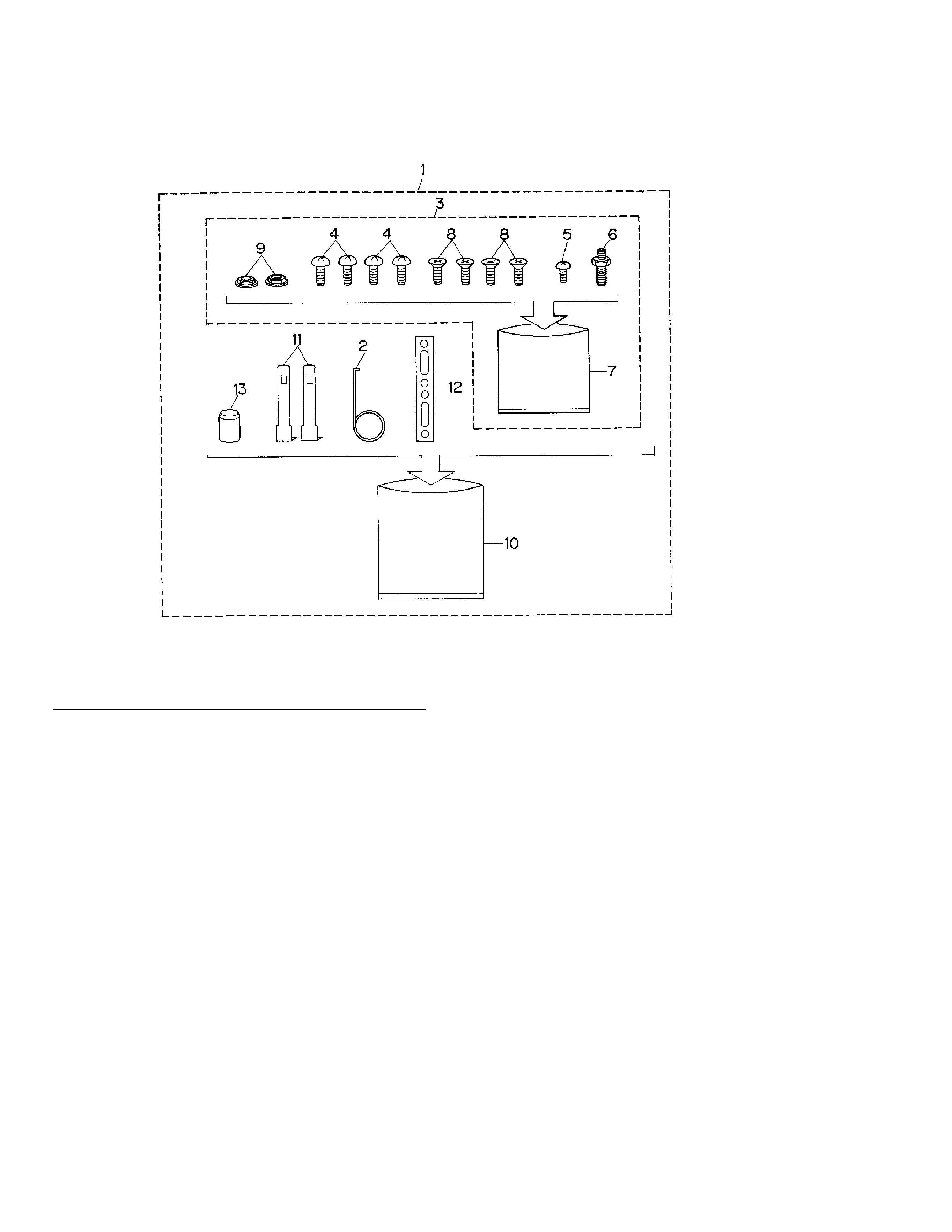
1 Accessory Assy
CEA2467
2 Spring
CBH-865
3 Screw Assy
CEA2465
4 Screw
BMZ50P060FMC
5 Screw
CBA-102
6 Screw
CBA1002
*
7 Polyethylene Bag
CEG-127
8 Screw
CMZ50P060FMC
9 Nut
NF50FMC
*
10 Polyethylene Bag
CEG-158
11 Handle
CNC5395
12 Strap
CNF-111
13 Bush
CNV1009
- ACCESSORY ASSY PARTS LIST
Mark No. Description
Part No.
2.2 ACCESSORY ASSY
5
AVX-505
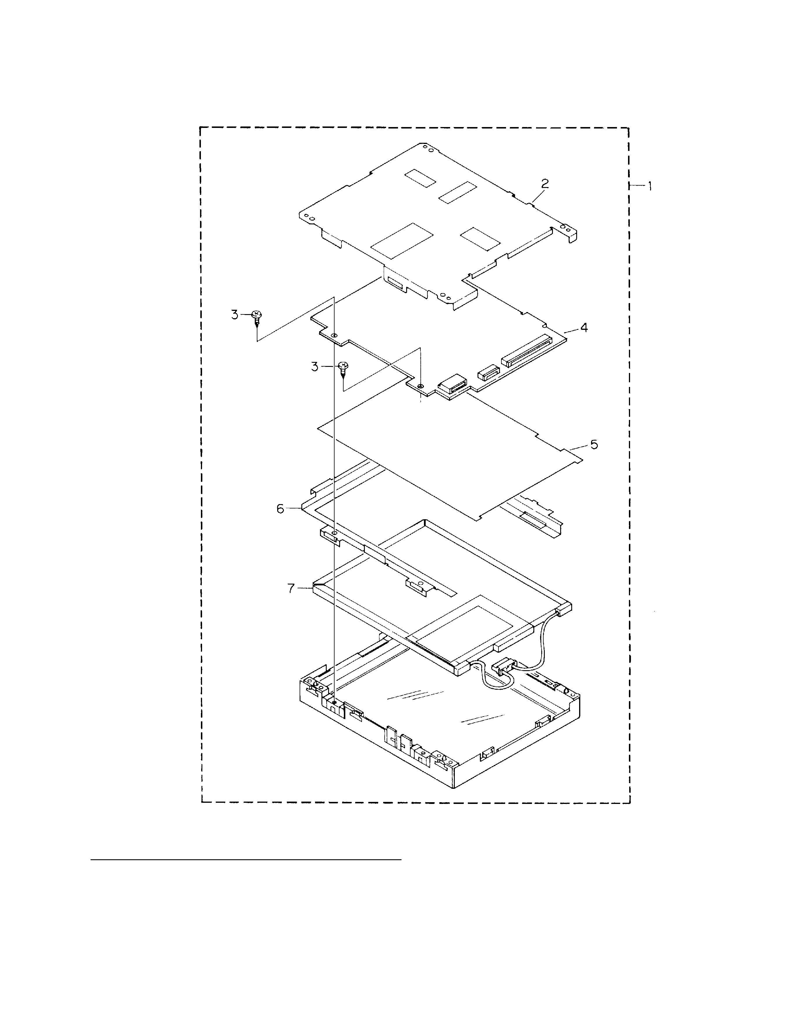
2.3 LCD 5.5 MONITOR
1 LCD 5.5 Monitor
CWX2010
2 Rear Frame
CZN3087
3 Screw
PPZ20P040FMC
4 PCB Unit
CZW3050
5 Sheet
CZM3006
6 Side Frame
CZN3008
7 Back Light Assy
CZW3051
- LCD 5.5 MONITOR PARTS LIST
Mark No. Description
Part No.