ORDER NO.
PIONEER CORPORATION 4-1, Meguro 1-chome, Meguro-ku, Tokyo 153-8654, Japan
PIONEER ELECTRONICS (USA) INC. P.O. Box 1760, Long Beach, CA 90801-1760, U.S.A.
PIONEER EUROPE NV Haven 1087, Keetberglaan 1, 9120 Melsele, Belgium
PIONEER ELECTRONICS ASIACENTRE PTE. LTD. 253 Alexandra Road, #04-01, Singapore 159936
PIONEER CORPORATION 2007
AVIC-D3/XU/UC
CRT3879
DVD MULTIMEDIA AV NAVIGATION SERVER
AVIC-D3
/XU/UC
AVIC-D3/XU/EW5
This service manual should be used together with the following manual(s):
Model No.
Order No.
Mech.Module
Remarks
CX-3212
CRT3896
MS5
DVD Mech. Module : Circuit Descriptions, Mech. Descriptions, Disassembly
For details, refer to "Important Check Points for Good Servicing".
K-ZZW. FEB. 2007 Printed in Japan
AVIC-D3/XU/UC
2
12
34
12
3
4
C
D
F
A
B
E
SAFETY INFORMATION
1. Safety Precautions for those who Service this Unit.
· Follow the adjustment steps in the service manual when servicing this unit. When check -
ing or adjusting the emitting power of the laser diode exercise caution in order to get safe, reliable results.
Caution:
1. During repair or tests, minimum distance of 13cm from the focus lens must be kept.
2. During repair or tests, do not view laser beam for 10 seconds or longer.
CAUTION
This service manual is intended for qualified service technicians; it is not meant for the casual do-it-yourselfer.
Qualified technicians have the necessary test equipment and tools, and have been trained to properly and safely repair
complex products such as those covered by this manual.
and refer the repair to a qualified service technician.
WARNING
This product contains lead in solder and certain electrical parts contain chemicals which are known to the state of
California to cause cancer, birth defects or other reproductive harm.
Health & Safety Code Section 25249.6 - Proposition 65
This product contains mercury. Disposal of this material may be regulated due to environmental considerations.
For disposal or recycling information, please contact your local authorities or the Electronics Industries
Alliance: www.eiae.org.
Improperly performed repairs can adversely affect the safety and reliability of the product and may void the warranty.
If you are not qualified to perform the repair of this product properly and safely, you should not risk trying to do so
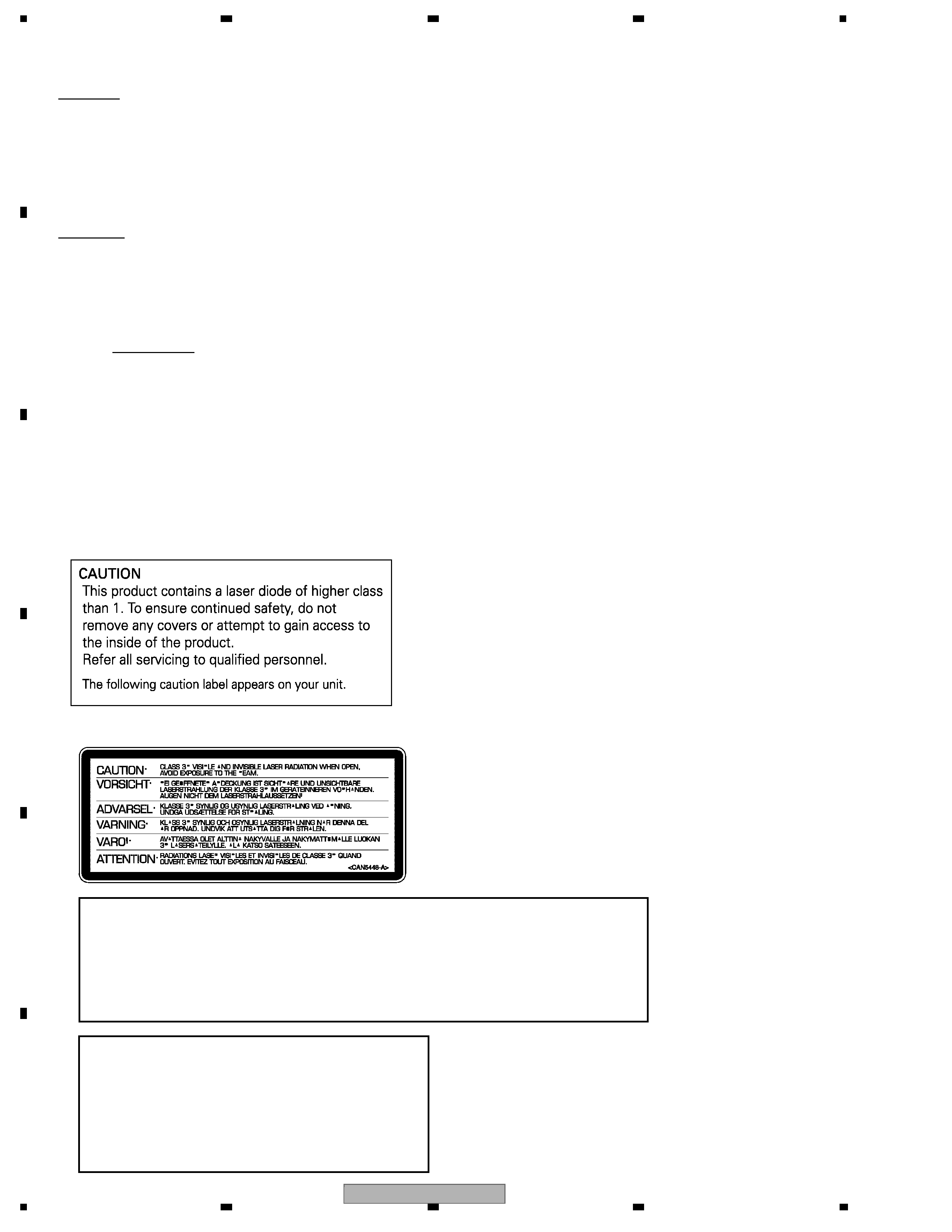
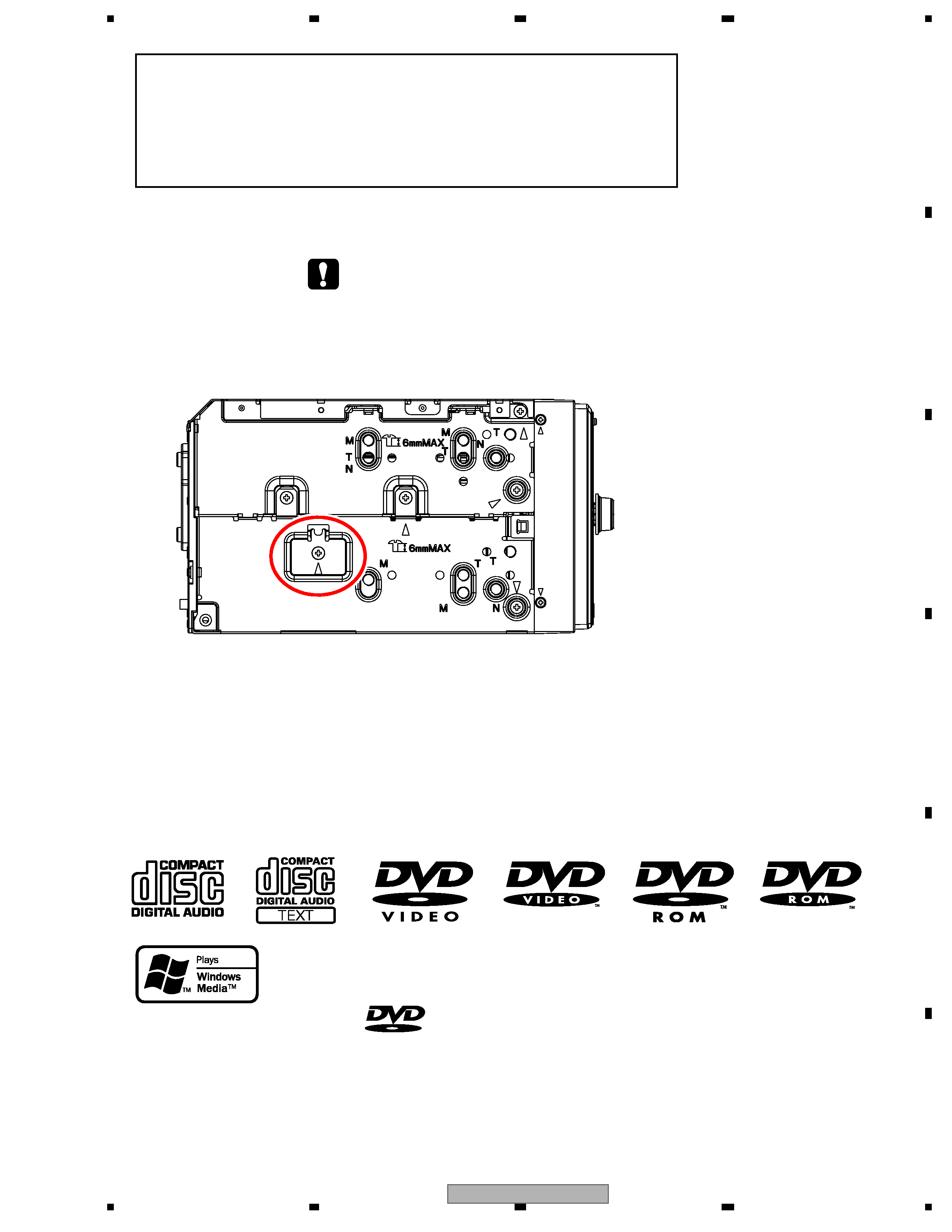
2. The trianglar label is attached to the mechanism unit frame.
On the top of the player.
WARNING!
The AEL (accessible emission level )of the laser power output is less than CLASS 1
but the laser component is capable of emitting radiation exceeding the limit for
CLASS 1.
A specially instructed person should do servicing operation of the apparatus.
Laser diode characteristics
Wave length:
DVD:660 nm to 670 nm
CD:780 nm to 800 nm
DVD : 1.27 mW(Emitting period :9 sec.)
CD : 6.26 mW(Emitting period : unlimited)
Maximum output:
AVIC-D3/XU/UC
3
56
7
8
56
7
8
C
D
F
A
B
E
Additional Laser Caution
Transistors Q1103 and Q1104 in PCB drive the laser diodes for DVD and CD
respectively. When Q1103 or Q1104 is shorted between their terminals,
the laser diodes for DVD or CD will radiate beam. If the top cover is removed
with no disc loaded while such short-circuit is continued, the naked eyes may
be exposed to the laser beam.
DVD MECHANISM MODULE section precaution
1. Before disassembling the unit, be sure to turn off the power. Unplugging and plugging the connectors
during power-on mode may damage the ICs inside the unit.
2. To protect the pickup unit from electrostatic discharge during servicing, take an appropriate treatment
(shorting-solder) by referring to "the DISASSEMBLY" .
3. After replacing the pickup unit, be sure to skew adjustment.
4. During disassembly, be sure to turn the power off since an internal IC might be destroyed when a
connector is plugged or unplugged.
- Service Precautions
1. You should conform to the regulations governing the product (safety, radio and noise, and other regulations),
and should keep the safety during servicing by following the safety instructions described in this manual.
2. Be careful in handling ICs. Some ICs such as MOS type are so fragile that they can be damaged by electrostatic
induction.
3. Because a part to show in figure below becomes hot, take care upon its operation.
is a trademark of DVD Format/Logo Licensing Corporation.
AVIC-D3/XU/UC
4
12
34
12
3
4
C
D
F
A
B
E
[Important Check Points for Good Servicing]
In this manual, procedures that must be performed during repairs are marked with the below symbol.
Please be sure to confirm and follow these procedures.
1. Product safety
Please conform to product regulations (such as safety and radiation regulations), and maintain a safe servicing environment by
following the safety instructions described in this manual.
1 Use specified parts for repair.
Use genuine parts. Be sure to use important parts for safety.
2 Do not perform modifications without proper instructions.
Please follow the specified safety methods when modification(addition/change of parts) is required due to interferences such as
radio/TV interference and foreign noise.
3 Make sure the soldering of repaired locations is properly performed.
When you solder while repairing, please be sure that there are no cold solder and other debris.
Soldering should be finished with the proper quantity. (Refer to the example)
4 Make sure the screws are tightly fastened.
Please be sure that all screws are fastened, and that there are no loose screws.
5 Make sure each connectors are correctly inserted.
Please be sure that all connectors are inserted, and that there are no imperfect insertion.
6 Make sure the wiring cables are set to their original state.
Please replace the wiring and cables to the original state after repairs.
In addition, be sure that there are no pinched wires, etc.
7 Make sure screws and soldering scraps do not remain inside the product.
Please check that neither solder debris nor screws remain inside the product.
8 There should be no semi-broken wires, scratches, melting, etc. on the coating of the power cord.
Damaged power cords may lead to fire accidents, so please be sure that there are no damages.
If you find a damaged power cord, please exchange it with a suitable one.
9 There should be no spark traces or similar marks on the power plug.
When spark traces or similar marks are found on the power supply plug, please check the connection and advise on secure
connections and suitable usage. Please exchange the power cord if necessary.
0 Safe environment should be secured during servicing.
When you perform repairs, please pay attention to static electricity, furniture, household articles, etc. in order to prevent injuries.
Please pay attention to your surroundings and repair safely.
2. Adjustments
To keep the original performance of the products, optimum adjustments and confirmation of characteristics within specification.
Adjustments should be performed in accordance with the procedures/instructions described in this manual.
4. Cleaning
For parts that require cleaning, such as optical pickups, tape deck heads, lenses and mirrors used in projection monitors, proper
cleaning should be performed to restore their performances.
3. Lubricants, Glues, and Replacement parts
Use grease and adhesives that are equal to the specified substance.
Make sure the proper amount is applied.
5. Shipping mode and Shipping screws
To protect products from damages or failures during transit, the shipping mode should be set or the shipping screws should be
installed before shipment. Please be sure to follow this method especially if it is specified in this manual.

AVIC-D3/XU/UC
5
56
7
8
56
7
8
C
D
F
A
B
E
CONTENTS
SAFETY INFORMATION......................................................................................................................................2
1. SPECIFICATIONS .............................................................................................................................................6
2. EXPLODED VIEWS AND PARTS LIST...........................................................................................................10
2.1 PACKING (UC) .........................................................................................................................................10
2.2 PACKING (EW5) .......................................................................................................................................12
2.3 EXTERIOR (1) ..........................................................................................................................................14
2.4 EXTERIOR (2) ..........................................................................................................................................16
2.5 EXTERIOR (3) ..........................................................................................................................................18
2.6 DVD MECHANISM MODULE ...................................................................................................................20
3. BLOCK DIAGRAM AND SCHEMATIC DIAGRAM ..........................................................................................22
3.1 BLOCK DIAGRAM ....................................................................................................................................22
3.2 OVERALL CONNECTION DIAGRAM ......................................................................................................40
3.3 NAVI MOTHER UNIT (CPU, ASIC, SDRAM)(GUIDE PAGE) ...................................................................42
3.4 NAVI MOTHER UNIT (ROM, SRAM, BUS-BUFFER)...............................................................................48
3.5 NAVI MOTHER UNIT (GRAPHIC)(GUIDE PAGE)....................................................................................50
3.6 NAVI MOTHER UNIT (MAIN, CC I/F) .......................................................................................................56
3.7 NAVI MOTHER UNIT (SYSTEM uCOM)(GUIDE PAGE) ..........................................................................58
3.8 NAVI MOTHER UNIT (I/F)(GUIDE PAGE) ................................................................................................64
3.9 NAVI MOTHER UNIT (PS)(GUIDE PAGE) ...............................................................................................70
3.10 GPS UNIT(GUIDE PAGE) ......................................................................................................................76
3.11 AV UNIT (PS, I/F) ...................................................................................................................................82
3.12 AV UNIT (A/V)(GUIDE PAGE) ................................................................................................................84
3.13 AV UNIT (TUNER) ..................................................................................................................................90
3.14 DVD CORE UNIT (1/2)(GUIDE PAGE) ...................................................................................................92
3.15 DVD CORE UNIT (2/2) ...........................................................................................................................98
3.16 COMPOUND UNIT(A), COMPOUND UNIT(B).....................................................................................102
3.17 MONITOR UNIT (VIDEO)(GUIDE PAGE).............................................................................................104
3.18 MONITOR UNIT (INVERTER) ..............................................................................................................110
3.19 KEY PCB ..............................................................................................................................................114
3.20 AV MINI JACK PCB ..............................................................................................................................116
4. PCB CONNECTION DIAGRAM ....................................................................................................................118
4.1 NAVI MOTHER UNIT..............................................................................................................................118
4.2 AV UNIT..................................................................................................................................................122
4.3 DVD CORE UNIT....................................................................................................................................126
4.4 COMPOUND UNIT(A), COMPOUND UNIT(B).......................................................................................130
4.5 GPS UNIT...............................................................................................................................................131
4.6 MONITOR UNIT .....................................................................................................................................132
4.7 KEY PCB ................................................................................................................................................136
4.8 AV MINI JACK PCB ................................................................................................................................137
5. ELECTRICAL PARTS LIST ...........................................................................................................................138
6. ADJUSTMENT ..............................................................................................................................................164
6.1 JIG CONNECTION DIAGRAM ...............................................................................................................164
6.2 DVD ADJUSTMENT ...............................................................................................................................165
6.3 MONITOR UNIT ADJUSTMENT ............................................................................................................196
6.4 SERVICE ADJUSTMENT .......................................................................................................................205
6.5 EEPROM ADJUSTMENT .......................................................................................................................207
6.6 PHASE ADJUSTMENT ..........................................................................................................................213
6.7 RGB ILLUMINATION ADJUSTMENT .....................................................................................................215
6.8 TOUCH PANEL TEST MODE .................................................................................................................217
6.9 NAVIGATION TEST MODE ....................................................................................................................223
6.10 USING THE TEST DISC.......................................................................................................................242
7. GENERAL INFORMATION ...........................................................................................................................254
7.1 DIAGNOSIS ............................................................................................................................................254
7.1.1 DISASSEMBLY....................................................................................................................................254
7.1.2 CONNECTOR FUNCTION DESCRIPTION ........................................................................................260
7.2 IC ............................................................................................................................................................261
7.3 EXPLANATION .......................................................................................................................................293
7.3.1 CIRCUIT DESCRIPTIONS ..................................................................................................................293
7.3.2 OPERATIONAL FLOW CHART ...........................................................................................................294
8. OPERATIONS ...............................................................................................................................................296