ORDER NO.
PIONEER CORPORATION 4-1, Meguro 1-chome, Meguro-ku, Tokyo 153-8654, Japan
PIONEER ELECTRONICS (USA) INC. P.O. Box 1760, Long Beach, CA 90801-1760, U.S.A.
PIONEER EUROPE NV Haven 1087, Keetberglaan 1, 9120 Melsele, Belgium
PIONEER ELECTRONICS ASIACENTRE PTE. LTD. 253 Alexandra Road, #04-01, Singapore 159936
PIONEER CORPORATION 2005
CRT3446
DVD NAVIGATION UNIT
AVIC-880DVD
/UC
This service manual should be used together with the manual(s) listed below. For the
parts numbers, adjustments, etc. which are not shown in this manual, refer to the follow-
ing manual(s).
Model No.
Order No.
Mech.Module
Remarks
AVIC-90DVD/UC
CRT2890
CX-954
CRT2670
MS2
DVD Mech. Module : Circuit Description, Mech. Description, Disassembly
is a trademark of DVD Format/Logo Licensing Corporation.
For details, refer to "Important Check Points for Good Servicing".
K-ZZA. MAR. 2005 Printed in Japan
This product has the unit part numbers as below.
*) The unit part number listed above are not for the service components.
Unit Part No.
Description
CPN2013
Main Assy
AVIC-880DVD/UC
2
12
34
12
3
4
C
D
F
A
B
E
[Important Check Points for Good Servicing]
In this manual, procedures that must be performed during repairs are marked with the below symbol.
Please be sure to confirm and follow these procedures.
1. Product safety
Please conform to product regulations (such as safety and radiation regulations), and maintain a safe servicing environment by
following the safety instructions described in this manual.
1 Use specified parts for repair.
Use genuine parts. Be sure to use important parts for safety.
2 Do not perform modifications without proper instructions.
Please follow the specified safety methods when modification(addition/change of parts) is required due to interferences such as
radio/TV interference and foreign noise.
3 Make sure the soldering of repaired locations is properly performed.
When you solder while repairing, please be sure that there are no cold solder and other debris.
Soldering should be finished with the proper quantity. (Refer to the example)
4 Make sure the screws are tightly fastened.
Please be sure that all screws are fastened, and that there are no loose screws.
5 Make sure each connectors are correctly inserted.
Please be sure that all connectors are inserted, and that there are no imperfect insertion.
6 Make sure the wiring cables are set to their original state.
Please replace the wiring and cables to the original state after repairs.
In addition, be sure that there are no pinched wires, etc.
7 Make sure screws and soldering scraps do not remain inside the product.
Please check that neither solder debris nor screws remain inside the product.
8 There should be no semi-broken wires, scratches, melting, etc. on the coating of the power cord.
Damaged power cords may lead to fire accidents, so please be sure that there are no damages.
If you find a damaged power cord, please exchange it with a suitable one.
9 There should be no spark traces or similar marks on the power plug.
When spark traces or similar marks are found on the power supply plug, please check the connection and advise on secure
connections and suitable usage. Please exchange the power cord if necessary.
0 Safe environment should be secured during servicing.
When you perform repairs, please pay attention to static electricity, furniture, household articles, etc. in order to prevent injuries.
Please pay attention to your surroundings and repair safely.
2. Adjustments
To keep the original performance of the products, optimum adjustments and confirmation of characteristics within specification.
Adjustments should be performed in accordance with the procedures/instructions described in this manual.
4. Cleaning
For parts that require cleaning, such as optical pickups, tape deck heads, lenses and mirrors used in projection monitors, proper
cleaning should be performed to restore their performances.
3. Lubricants, Glues, and Replacement parts
Use grease and adhesives that are equal to the specified substance.
Make sure the proper amount is applied.
5. Shipping mode and Shipping screws
To protect products from damages or failures during transit, the shipping mode should be set or the shipping screws should be
installed before shipment. Please be sure to follow this method especially if it is specified in this manual.
AVIC-880DVD/UC
3
56
7
8
56
7
8
C
D
F
A
B
E
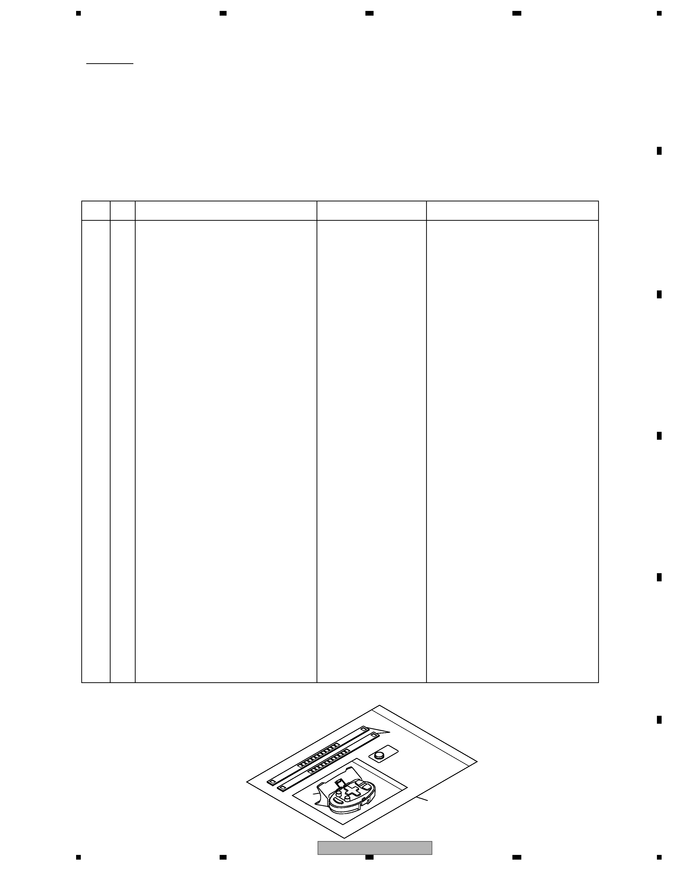
EXPLODED VIEWS AND PARTS LIST
PACKING(Page 6)
PACKING SECTION PARTS LIST
* : Non spare part
Mark No.
Description
AVIC-90DVD/UC
AVIC-880DVD/UC
1-1 Owner's Manual
CRB1798
CRB2075
1-2 Owner's Manual/PA/FRE
CRB1783
CRB2077(Owner's Manual/POC/FRE)
1-3 Owner's Manual
CRB1796
CRB2074
1-4 Owner's Manual/PA/FRE
CRB1797
CRB2076(Owner's Manual/POC/FRE)
1-5 Installation Manual
CRD3650
Not used
1-6 Owner's Manual
CRD3661
CRD3982(Installation Manual)
*
1-10 Registration Card
Not used
CRY1229
2
Cord Assy
CDE7062
CDE7725
3
Accessory Assy
CEA2913
CEA4467
8
Accessory Assy
CEA2536
CEA4299(Connector Assy)
9
Polyethylene Bag
CEG1011
* E36-615
10
Battery
CEX1021
Not used
12
Sheet
CNM6370
Not used
13
Holder
CNS5606
Not used
17
Screw Assy
CEA2896
CEA4465
19
Screw
CMZ50P060FMC
CMZ50P060FTC
23
Carton
CHG4738
CHG5538
25
Contain Box
CHL4738
CHL5538
31
Remote Control Assy
CXB9118
Not used
34
DVD-ROM
CPJ1143
CZP3025
35
Screw Assy
CEA2938
CEA4466
36
Screw(M6x16)
CBA1295
CBA1795
*
37
Polyethylene Bag
E36-613
CNM4338(Polyethylene Sheet)
38
Remote Control Assy
Not used
CXC3646
39
Belt
Not used
CZN5499
40
Holder
Not used
CZN7041
38
40
39
SAFETY INFORMATION
WARNING
This product contains lead in solder and certain electrical parts contain chemicals which are known to the state of
California to cause cancer, birth defects or other reproductive harm.
Health & Safety Code Section 25249.6 - Proposition 65
AVIC-880DVD/UC
4
12
34
12
3
4
C
D
F
A
B
E
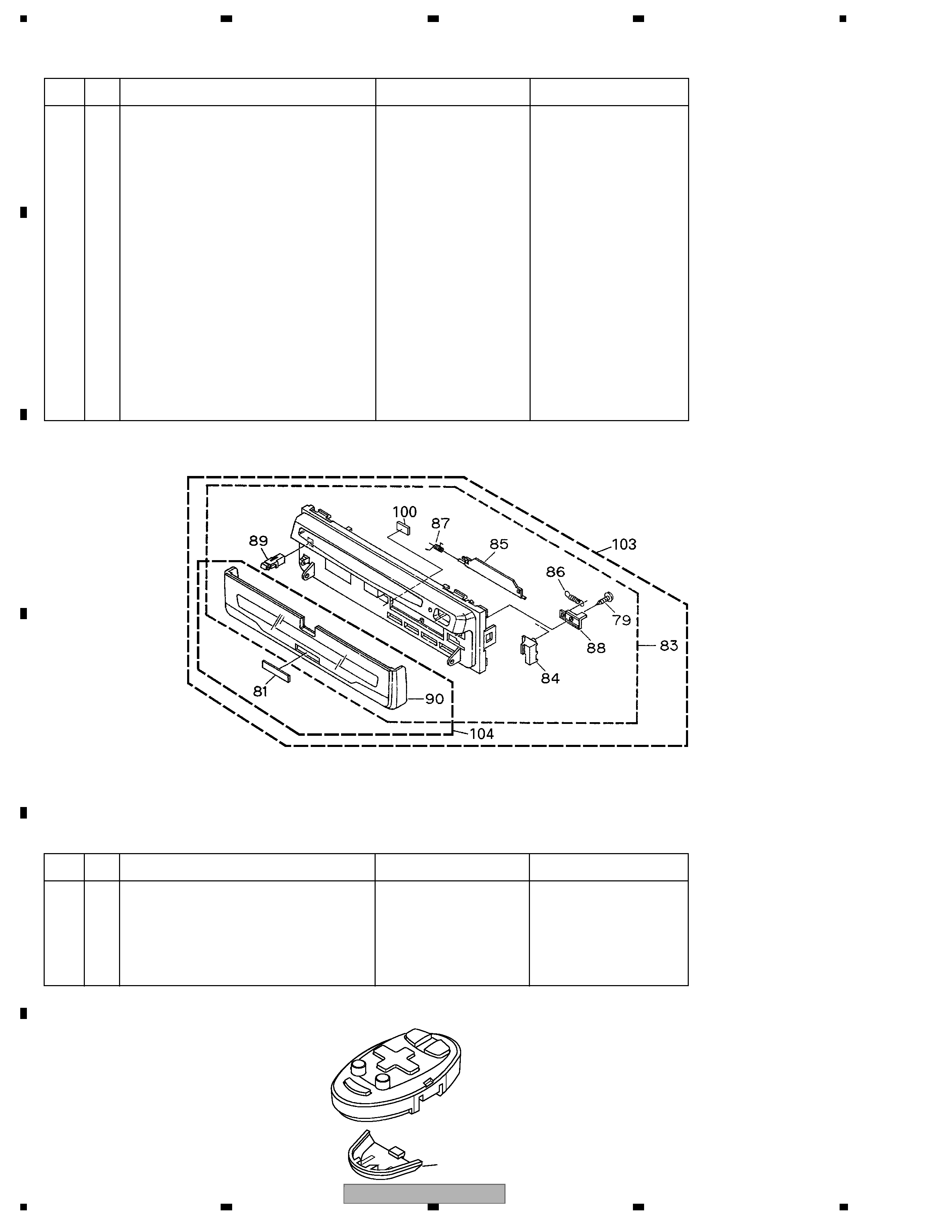
EXTERIOR(Page 12)
EXTERIOR SECTION PARTS LIST
Mark No.
Description
AVIC-90DVD/UC
AVIC-880DVD/UC
1
Screw
BMZ20P025FMC
BMZ20P025FTC
2
Screw
BMZ26P040FMC
BMZ26P040FTC
23
CC Unit
CWM8391
CWM9059
36
Screw
IMS26P030FMC
IMS26P030FTC
37
Main Unit
CWM8484
CWM9642
73
GPS Unit
CWX2591
CWX2925
79
Screw
BPZ20P050FMC
BPZ20P050FTC
83
Grille Unit
CXB9890
CXC4908
90
Door Unit
CXB7566
CXC3674
91
DVD Mechanism Module(MS2)
CXK6160
CXK6121
96
Cord Assy
CDE7062
CDE7725
103 Grille Unit
GXX1229
GXX1251
104 Door Unit
GXX1223
GXX1247
REMOTE CONTROL ASSY(Page 16)
REMOTE CONTROL ASSY SECTION PARTS LIST
Mark No.
Description
AVIC-90DVD/UC
AVIC-880DVD/UC
1
Remote Control Assy
CXB9118
Not used
2
Cover
CZN5432
Not used
3
Scroll Stick
CZA5047
Not used
4
3D View Stick
CZA5085
Not used
5
Cover
Not used
CZN5497
5
AVIC-880DVD/UC
5
56
7
8
56
7
8
C
D
F
A
B
E
ELECTRICAL PARTS LIST(Page 110)
The > mark found on some component parts indicatesthe importance of the safety factor of the part.
Therefore, when replacing, be sure to use parts of identical designation.
MAIN UNIT
Circuit Symbol and No.
AVIC-90DVD/UC
AVIC-880DVD/UC
IC571 IC
S-81250SGUP
S-812C50AUA-C3E
IC631 IC
S-8423AFS
S-8424AABFT
D1841 Diode
MA110
MA111
>FU1801 Fuse 2A
CEK1190
CEK1257
>FU1802, 1804 Fuse 4A
CEK1199
CEK1260
>FU1850, 3251 Fuse 1A
CEK1191
CEK1254
GY572 Sensor
CSX1052
CSX1050
R607
RS1/16S104J
Not used
R608
Not used
RS1/16S104J
Page 31 7-B
ADJUSTMENT
USING THE TEST DISC(Page 166)
AVIC-90DVD/UC
AVIC-880DVD/UC
TEST DISC
GGV1059(CNDK-LT0102)
GGV1132(S-57364)
Circuit Symbol and No.
AVIC-90DVD/UC
AVIC-880DVD/UC
IC110 IC
PD6403B
PD6444B
IC111 IC
PD6404B
PD6445B
>FU801 Fuse 4A
CEK1199
CEK1260
>FU802, 803 Fuse 2.5A
CEK1209
CEK1258
GPS UNIT
Circuit Symbol and No.
AVIC-90DVD/UC
AVIC-880DVD/UC
IC502 IC
PD6362B
PD6452A
CC UNIT