PIONEER CORPORATION
4-1, Meguro 1-Chome, Meguro-ku, Tokyo 153-8654, Japan
PIONEER ELECTRONICS (USA) INC.
P.O.Box 1760, Long Beach, CA 90801-1760 U.S.A.
PIONEER EUROPE NV
Haven 1087 Keetberglaan 1, 9120 Melsele, Belgium
PIONEER ELECTRONICS ASIACENTRE PTE.LTD. 253 Alexandra Road, #04-01, Singapore 159936
C PIONEER CORPORATION 2003
K-ZZU. JUNE 2003 Printed in Japan
ORDER NO.
CRT3039
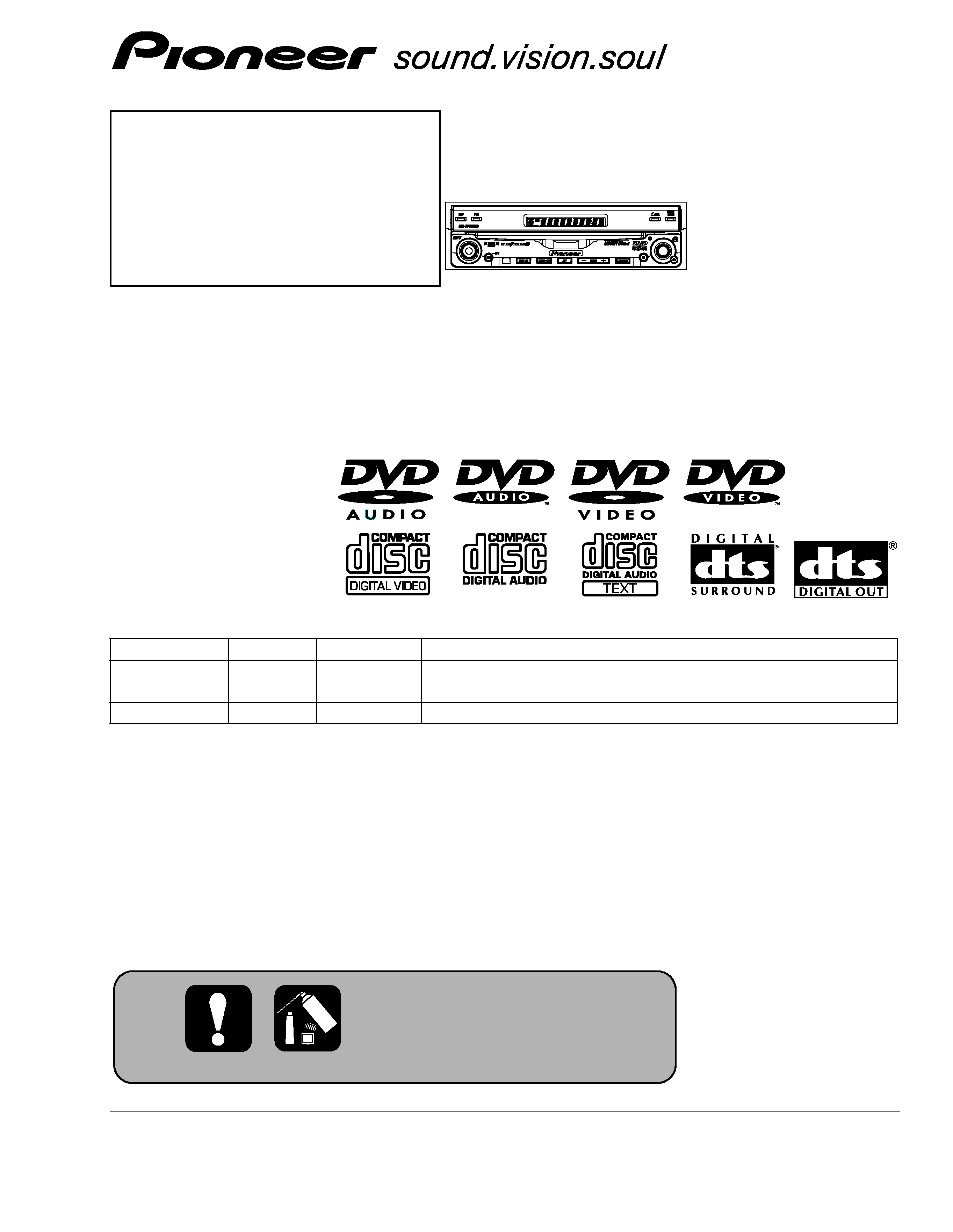
7 INCH WIDE FULLY MOTORIZED LCD COLOR DISPLAY WITH 5 CHANNEL HIGH-POWER DVD/VCD/CD RECEIVER
Service
Manual
AVH-P7500DVD/UC
NOTE:
- Manufactured under license from Dolby Laboratories. "Dolby" and the double-D symbol are trademarks of Dolby
Laboratories.
- Inverter for LCD back light becomes a high voltage.
For details, refer to "Important symbols for good services".
- This service manual should be used together with the following manual(s):
Model No.
Order No.
Mech. Module Remarks
AVH-P7500DVD
CRT3112
ADJUSTMENT, GENERAL INFORMATION AND OPERATIONS
/UC,EW
CX-3016
CRT3056
MS3
DVD Mech. Module:Circuit Description, Mech.Description, Disassembly
AVH-P7500DVD
UC,EW
2
1
234
12
34
F
E
D
C
B
A
AVH-P7500DVD/UC
SAFETY INFORMATION
- DVD Player Service Precautions
1. Before disassembling the unit, be sure to turn off the power. Unplugging and plugging the connectors during
power-on mode may damage the ICs inside the unit.
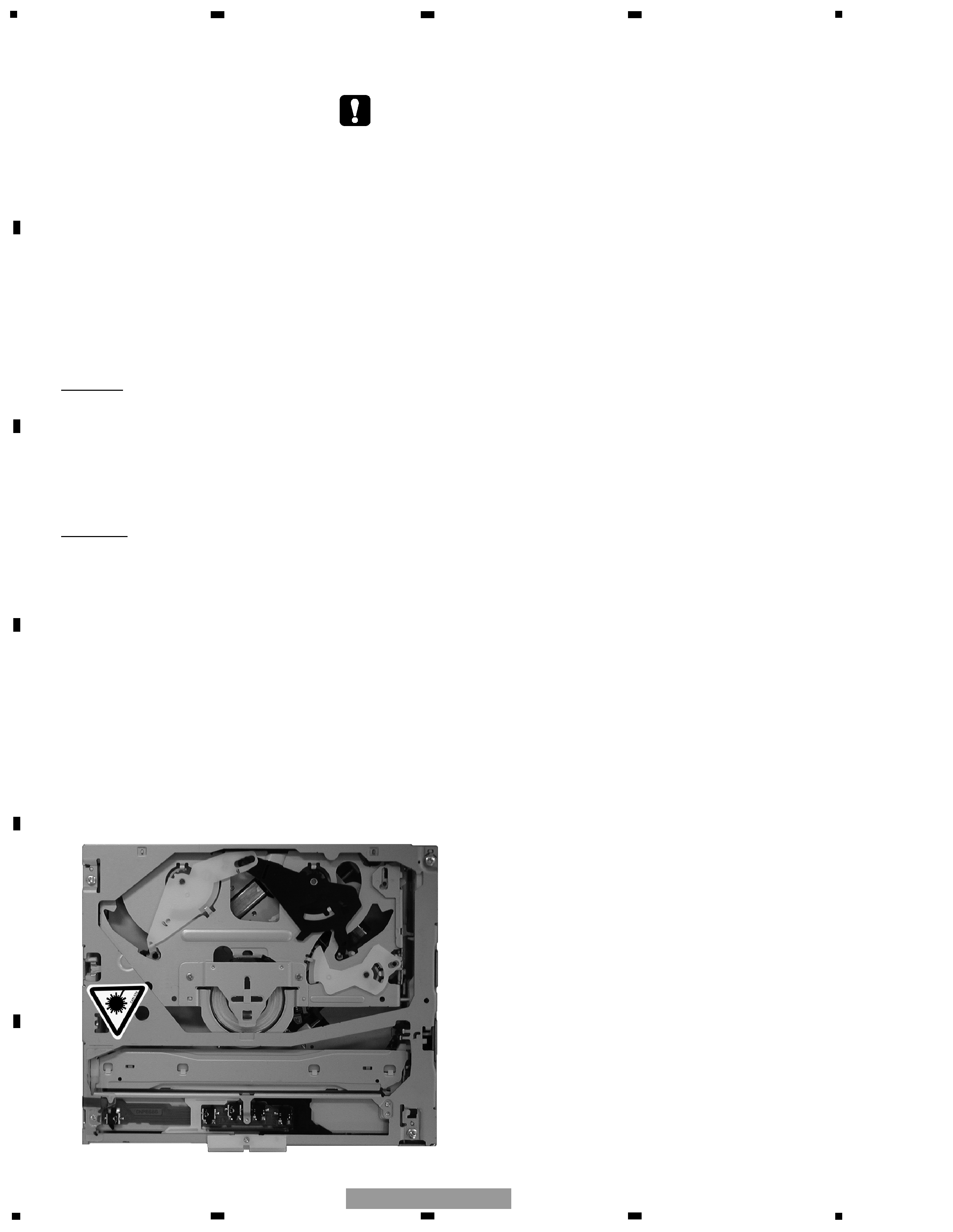
2. To protect the pickup unit from electrostatic discharge during servicing, take an appropriate treatment (shorting-sol-
der) by referring to " the DISASSEMBLY" on page 49 of CRT3112.
3. Please adjusting the skew after changing the pickup unit(see page 8 of CRT3112).
4. During disassembly, be sure to turn the power off since an internal IC might be destroyed when a connector is
plugged or unplugged.
UC
CAUTION
This service manual is intended for qualified service technicians; it is not meant for the casual do-it-yourselfer.
Qualified technicians have the necessary test equipment and tools, and have been trained to properly and safely repair
complex products such as those covered by this manual.
Improperly performed repairs can adversely affect the safety and reliability of the product and may void the warranty.
If you are not qualified to perform the repair of this product properly and safely, you should not risk trying to do so
and refer the repair to a qualified service technician.
WARNING
This product contains lead in solder and certain electrical parts contain chemicals which are known to the state of
California to cause cancer, birth defects or other reproductive harm.
Health & Safety Code Section 25249.6 - Proposition 65
EW
1. Safety Precautions for those who Service this Unit.
· Follow the adjustment steps (see pages 4 of CRT3112 through 48 of CRT3112)in the service manual when servicing-
this unit. When checking or adjusting the emitting power of the laser diode exercise caution in order to get safe,
reliable results.
Caution:
1. During repair or tests, minimum distance of 13cm from the focus lens must be kept.
2. During repair or tests, do not view laser beam for 10 seconds or longer.
2. The triangular label is attached to the mechanism
unit frame.
3
5
6
7
8
F
E
D
C
B
A
5
6
7
8
AVH-P7500DVD/UC
On the top of the player.
CAUTION :
VORSICHT :
ADVARSEL :
VARNING :
VARO!
:
VISIBLE AND INVISIBLE LASER RADIATION WHEN OPEN.
AVOID EXPOSURE TO BEAM.
SICHTBARE UND UNSICHTBARE LASERSTRAHLUNG, WENN
ABDECKUNG GEÖFFNET NICHT DEM STRAHL AUSSETZEN!
SYNLIG OG USYNLIG LASERSTRÅLING VED ÅBNING
UNDGÅ UDSÆTTELSE FOR STRÀLING.
SYNLIG OCH OSYNLIG LASERSTRÅLNING NÄR DENNA
DEL ÄR ÖPPNAD BETRAKTA EJ STRÅLEN.
AVATTAESSA ALTISTUT NÄKYVÄ JA NÄKYMÄTTÖMÄLLE
LASERSATEIL YLLE. ÄLÄ KATSO SÄTEESEN.
VRW1860
CLASS 1
LASER PRODUCT
WARNING!
The AEL (accessible emission level )of the laser power output is less than CLASS 1
but the laser component is capable of emitting radiation exceeding the limit for
CLASS 1.
A specially instructed person should do servicing operation of the apparatus.
Laser diode characteristics
Wave length:
DVD:640~660nm
CD:770~810nm
Maximum output:2.44mw(Emitting period :9sec.)
DVD:743mw(Emitting period : unlimited)
Additionla Laser Caution
Transistors Q1101 and Q1102 in PCB drive the laser diodes for DVD and CD
respectively. When Q1101 or Q1102 is shorted between their terminals,
the laser diodes for DVD or CD will radiate beam. If the top cover is removed
with no disc loaded while such short-circuit is continued, the naked eyes may
be exposed to the laser beam.
CAUTION
Danger of explosion if battery is incorrectly replaced.
Replaced only with the same or equivalent type recommended by the manufacture.
Discord used batteries according to the manufacture's instructions.
4
[ Important symbols for good services ]
In this manual, the symbols shown-below indicate that adjustments, settings or cleaning should be made securely.
When you find the procedures bearing any of the symbols, be sure to fulfill them:
2. Adjustments
To keep the original performances of the product, optimum adjustments or specification confirmation is indispensable.
In accordance with the procedures or instructions described in this manual, adjustments should be performed.
3. Cleaning
For optical pickups, tape-deck heads, lenses and mirrors used in projection monitors, and other parts requiring cleaning,
proper cleaning should be performed to restore their performances.
5. Lubricants, glues, and replacement parts
Appropriately applying grease or glue can maintain the product performances. But improper lubrication or applying
glue may lead to failures or troubles in the product. By following the instructions in this manual, be sure to apply the
prescribed grease or glue to proper portions by the appropriate amount.For replacement parts or tools, the prescribed
ones should be used.
4. Shipping mode and shipping screws
To protect the product from damages or failures that may be caused during transit, the shipping mode should be set or
the shipping screws should be installed before shipping out in accordance with this manual, if necessary.
1. Product safety
You should conform to the regulations governing the product (safety, radio and noise, and other regulations), and
should keep the safety during servicing by following the safety instructions described in this manual.
1
234
12
34
F
E
D
C
B
A
AVH-P7500DVD/UC

5
5
6
7
8
F
E
D
C
B
A
5
6
7
8
AVH-P7500DVD/UC
CONTENTS
SAFETY INFORMATION ...............................................................................................................2
1. SPECIFICATIONS...........................................................................................................................6
2. EXPLODED VIEWS AND PARTS LIST ........................................................................................10
2.1 PACKING................................................................................................................................10
2.2 EXTERIOR(1) .........................................................................................................................14
2.3 EXTERIOR(2) .........................................................................................................................16
2.4 EXTERIOR(3) .........................................................................................................................18
2.5 TUNER SELECTOR ASSY(UC MODEL) ...............................................................................20
2.6 TUNER SELECTOR ASSY(EW MODEL)...............................................................................22
2.7 DVD MECHANISM MODULE ...............................................................................................24
3. BLOCK DIAGRAM AND SCHEMATIC DIAGRAM ......................................................................26
3.1 BLOCK DIAGRAM .................................................................................................................26
3.2 OVERALL CONNECTION DIAGRAM....................................................................................38
3.3 MOTHER PCB(SYSTEM)(GUIDE PAGE) ..............................................................................40
3.4 MOTHER PCB(GDC)(GUIDE PAGE)......................................................................................46
3.5 MOTHER PCB(DSP)(GUIDE PAGE) ......................................................................................52
3.6 MOTHER PCB(POWER)(GUIDE PAGE) ................................................................................58
3.7 RELAY PCB ............................................................................................................................64
3.8 EXTENSION PCB...................................................................................................................65
3.9 DVD CORE UNIT(MS3)(SODC)(GUIDE PAGE) ....................................................................66
3.10 DVD CORE UNIT(MS3)(CPU)(GUIDE PAGE) .....................................................................72
3.11 COMPOUND UNIT(A) AND COMPOUND UNIT(B)...........................................................80
3.12 PU UNIT(REFERENCE)........................................................................................................81
3.13 TUNER SELECTOR UNIT(TUNER SELECTOR)(UC MODEL)(GUIDE PAGE)....................82
3.14 TUNER SELECTOR UNIT(TV POWER)(UC MODEL)(GUIDE PAGE).................................88
3.15 TUNER SELECTOR UNIT(EW MODEL)(GUIDE PAGE) .....................................................94
3.16 MONITOR PCB,UPPER PCB AND SENSE PCB(GUIDE PAGE) .......................................100
3.17 INVERTER PCB ..................................................................................................................106
3.18 PANEL PCB ........................................................................................................................107
3.19 GRILLE PCB .......................................................................................................................108
3.20 MAIN UNIT,SW UNIT AND VOLUME UNIT ....................................................................110
3.21 TV TUNER UNIT(UC MODEL)(GUIDE PAGE) ..................................................................112
4. PCB CONNECTION DIAGRAM ....................................................................................................118
4.1 MOTHER PCB ......................................................................................................................118
4.2 RELAY PCB AND EXTENSION PCB ...................................................................................122
4.3 DVD CORE UNIT(MS3) .......................................................................................................124
4.4 COMPOUND UNIT(A) AND COMPOUND UNIT(B)...........................................................128
4.5 TUNER SELECTOR UNIT ....................................................................................................130
4.6 INVERTER PCB ....................................................................................................................134
4.7 MONITOR PCB ....................................................................................................................136
4.8 UPPER PCB ..........................................................................................................................140
4.9 SENSE PCB..........................................................................................................................141
4.10 GRILLE PCB .......................................................................................................................142
4.11 PANEL PCB ........................................................................................................................143
4.12 TV TUNER UNIT(UC MODEL) ..........................................................................................144
4.13 MAIN UNIT ........................................................................................................................146
4.14 SW UNIT AND VOLUME UNIT ........................................................................................148
5. ELECTRICAL PARTS LIST ............................................................................................................149