ORDER NO.
PIONEER CORPORATION 4-1, Meguro 1-chome, Meguro-ku, Tokyo 153-8654, Japan
PIONEER ELECTRONICS (USA) INC. P.O. Box 1760, Long Beach, CA 90801-1760, U.S.A.
PIONEER EUROPE NV Haven 1087, Keetberglaan 1, 9120 Melsele, Belgium
PIONEER ELECTRONICS ASIACENTRE PTE. LTD. 253 Alexandra Road, #04-01, Singapore 159936
PIONEER CORPORATION 2002
PAUSE
ATT
AVH-P6400CD/UC
CRT2853
AV RECEIVER/CD PLAYER WITH 6.5 INCH WIDE DISPLAY
AVH-P6400CD
UC
AVH-P6400CD
EW
AVH-P6450CD
ES
This service manual should be used together with the following manual(s):
-
-
-
-The inverter of this unit is at a high voltage when electrified, so there is a risk of electric
shocks. Make sure that power supply to the unit is OFF once again before operation.
Model No.
Order No.
Mech.Module
Remarks
CX-961
CRT2503
H2
CD Mech. module:Circuit Description, Mech.Description, Disassembly
For details, refer to "Important symbols for good services"
K-ZZU. APR. 2002.printed in Japan
AVH-P6400CD/UC
A
B
C
D
12
34
12
3
4
2
SAFETY INFORMATION
- Service Precautions
CD section precaution
1. Before disassembling the unit, be sure to turn off
the power. Unplugging and plugging the connectors
during power-on mode may damage the ICs inside
the unit.
2. To protect the pickup unit from electrostatic
discharge during servicing, take an appropriate
treatment (shorting pin) by referring to "the
DISASSEMBLY" on page 98.
3. After replacing the pickup unit, be sure to check
the grating. (See p.92.)
CAUTION
This service manual is intended for qualified service technicians; it is not meant for the casual do-it-yourselfer.
Qualified technicians have the necessary test equipment and tools, and have been trained to properly and safely repair
complex products such as those covered by this manual.
Improperly performed repairs can adversely affect the safety and reliability of the product and may void the warranty.
If you are not qualified to perform the repair of this product properly and safely, you should not risk trying to do so
and refer the repair to a qualified service technician.
WARNING
This product contains lead in solder and certain electrical parts contain chemicals which are known to the state of
California to cause cancer, birth defects or other reproductive harm.
Health & Safety Code Section 25249.6 - Proposition 65
UC
ES
CAUTION
Danger of explosion if battery is incorrectly replaced.
Replaced only with the same or equivalent type.
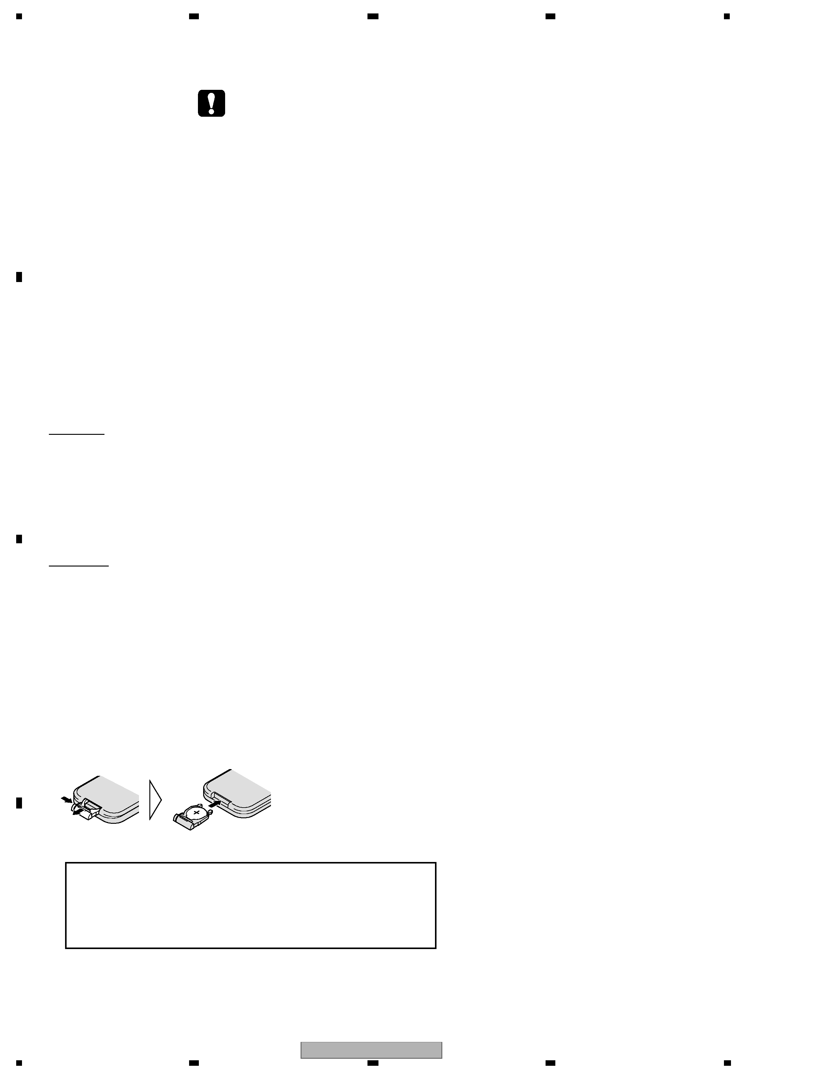
Battery
Slide the tray out on the back of the
remote controller and insert the battery
with the (+) and () poles pointing in
the proper direction.
Note :
· Use a CR2025 (3V) lithium battery
only. Never use other types of battery
with this unit.

AVH-P6400CD/UC
A
B
C
D
56
7
8
56
7
8
3
EW
This service manual is intended for qualified service technicians; it is not meant for the casual do-it-yourselfer.
Qualified technicians have the necessary test equipment and tools, and have been trained to properly and safely repair
complex products such as those covered by this manual.
Improperly performed repairs can adversely affect the safety and reliability of the product and may void the warranty.
If you are not qualified to perform the repair of this product properly and safely, you should not risk tr
and refer the repair to a qualified service technician.
1. Safety Precautions for those who Service this Unit.
· When checking or adjusting the emitting power of the laser diode exercise caution in order to get safe, reliable
results.
Caution:
1. During repair or tests, minimum distance of 13cm from the focus lens must be kept.
2. During repair or tests, do not view laser beam for 10 seconds or longer.
2. A "CLASS 1 LASER PRODUCT" label is affixed to the
bottom of the player.
3. The triangular label is attached to the mechanism
unit frame.
4. Specifications of Laser Diode
Specifications of laser radiation fields to which human access is possible during service.
Wavelength
=
800 nanometers
CLASS 1
LASER PRODUCT
ying to do so
CAUTION
Danger of explosion if battery is incorrectly replaced.
Replaced only with the same or equivalent type recommended by the manufacture.
Discord used batteries according to the manufacture's instructions.
AVH-P6400CD/UC
A
B
C
D
12
34
12
3
4
4
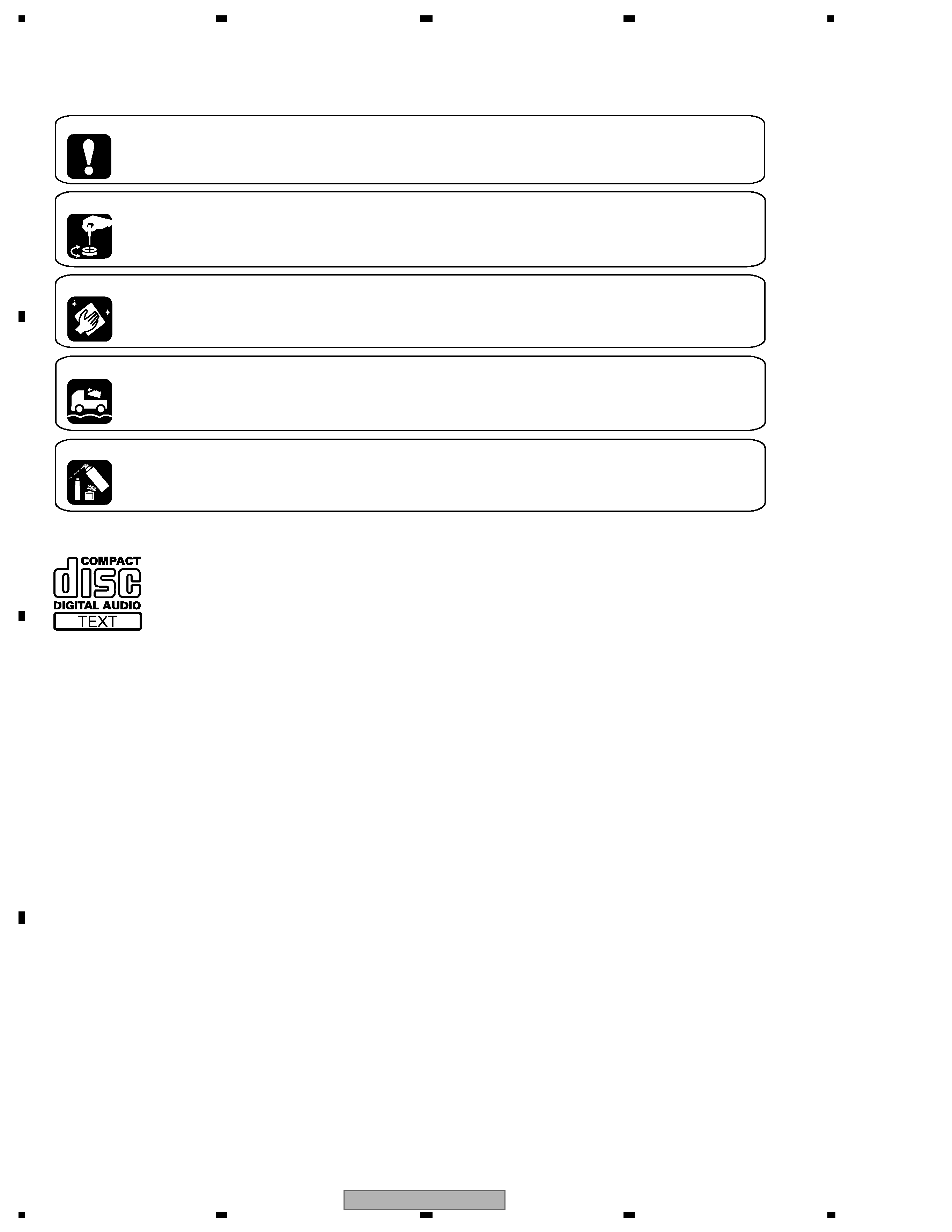
[ Important symbols for good services ]
In this manual, the symbols shown-below indicate that adjustments, settings or cleaning should be made securely.
When you find the procedures bearing any of the symbols, be sure to fulfill them:
2. Adjustments
To keep the original performances of the product, optimum adjustments or specification confirmation is indispensable.
In accordance with the procedures or instructions described in this manual, adjustments should be performed.
3. Cleaning
For optical pickups, tape-deck heads, lenses and mirrors used in projection monitors, and other parts requiring cleaning,
proper cleaning should be performed to restore their performances.
5. Lubricants, glues, and replacement parts
Appropriately applying grease or glue can maintain the product performances. But improper lubrication or applying
glue may lead to failures or troubles in the product. By following the instructions in this manual, be sure to apply the
prescribed grease or glue to proper portions by the appropriate amount.For replacement parts or tools, the prescribed
ones should be used.
4. Shipping mode and shipping screws
To protect the product from damages or failures that may be caused during transit, the shipping mode should be set or
the shipping screws should be installed before shipping out in accordance with this manual, if necessary.
1. Product safety
You should conform to the regulations governing the product (safety, radio and noise, and other regulations), and
should keep the safety during servicing by following the safety instructions described in this manual.

AVH-P6400CD/UC
A
B
C
D
56
7
8
56
7
8
5
CONTENTS
SAFETY INFORMATION. . . . . . . . . . . . . . . . . . . . . . . . . . . . . . . . . . . . . 2
1. SPECIFICATIONS . . . . . . . . . . . . . . . . . . . . . . . . . . . . . . . . . . . . . . . 6
2. EXPLODED VIEWS AND PARTS LIST . . . . . . . . . . . . . . . . . . . . . . . . . . . . 8
2.1 PACKING . . . . . . . . . . . . . . . . . . . . . . . . . . . . . . . . . . . . . . . . . 8
2.2 EXTERIOR(1) . . . . . . . . . . . . . . . . . . . . . . . . . . . . . . . . . . . . . . . 10
2.3 EXTERIOR(2) . . . . . . . . . . . . . . . . . . . . . . . . . . . . . . . . . . . . . . . 12
2.4 EXTERIOR(3) . . . . . . . . . . . . . . . . . . . . . . . . . . . . . . . . . . . . . . . 14
2.5 CD MECHANISM MODULE . . . . . . . . . . . . . . . . . . . . . . . . . . . . . . . . 16
3. BLOCK DIAGRAM AND SCHEMATIC DIAGRAM . . . . . . . . . . . . . . . . . . . . . . . 18
3.1 BLOCK DIAGRAM(1) . . . . . . . . . . . . . . . . . . . . . . . . . . . . . . . . . . . 18
3.2 BLOCK DIAGRAM(2) . . . . . . . . . . . . . . . . . . . . . . . . . . . . . . . . . . . 20
3.3 OVERALL CONNECTION DIAGRAM . . . . . . . . . . . . . . . . . . . . . . . . . . . 22
3.4 MOTHER PCB(GUIDE PAGE). . . . . . . . . . . . . . . . . . . . . . . . . . . . . . . 24
3.5 TUNER PCB . . . . . . . . . . . . . . . . . . . . . . . . . . . . . . . . . . . . . . . . 30
3.6 GRILLE PCB. . . . . . . . . . . . . . . . . . . . . . . . . . . . . . . . . . . . . . . . 32
3.7 RELAY PCB . . . . . . . . . . . . . . . . . . . . . . . . . . . . . . . . . . . . . . . . 33
3.8 INVERTER PCB . . . . . . . . . . . . . . . . . . . . . . . . . . . . . . . . . . . . . .34
3.9 MONITOR UNIT . . . . . . . . . . . . . . . . . . . . . . . . . . . . . . . . . . . . . .36
3.10 ENCODER UNIT . . . . . . . . . . . . . . . . . . . . . . . . . . . . . . . . . . . . . 40
3.11 CD MECHANISM MODULE . . . . . . . . . . . . . . . . . . . . . . . . . . . . . . . 42
4. PCB CONNECTION DIAGRAM . . . . . . . . . . . . . . . . . . . . . . . . . . . . . . . . 46
4.1 MOTHER PCB . . . . . . . . . . . . . . . . . . . . . . . . . . . . . . . . . . . . . . .46
4.2 TUNER PCB . . . . . . . . . . . . . . . . . . . . . . . . . . . . . . . . . . . . . . . . 50
4.3 GRILLE PCB. . . . . . . . . . . . . . . . . . . . . . . . . . . . . . . . . . . . . . . . 51
4.4 INVERTER PCB . . . . . . . . . . . . . . . . . . . . . . . . . . . . . . . . . . . . . .52
4.5 RELAY PCB,UPPER PCB . . . . . . . . . . . . . . . . . . . . . . . . . . . . . . . . . 53
4.6 MONITOR PCB . . . . . . . . . . . . . . . . . . . . . . . . . . . . . . . . . . . . . .54
4.7 ENCODER UNIT . . . . . . . . . . . . . . . . . . . . . . . . . . . . . . . . . . . . . 56
4.8 CD MECHANISM MODULE . . . . . . . . . . . . . . . . . . . . . . . . . . . . . . . . 58
5. ELECTRICAL PARTS LIST . . . . . . . . . . . . . . . . . . . . . . . . . . . . . . . . . . 60
6. ADJUSTMENT . . . . . . . . . . . . . . . . . . . . . . . . . . . . . . . . . . . . . . . . . 80
6.1 JIG CONNECTION DIAGRAM . . . . . . . . . . . . . . . . . . . . . . . . . . . . . . 80
6.2 MOTHER PCB ADJUSTMENT . . . . . . . . . . . . . . . . . . . . . . . . . . . . . . 81
6.3 INVERTER PCB ADJUSTMENT . . . . . . . . . . . . . . . . . . . . . . . . . . . . . 82
6.4 MONITOR PCB ADJUSTMENT . . . . . . . . . . . . . . . . . . . . . . . . . . . . . . 83
6.5 MONITOR TEST MODE . . . . . . . . . . . . . . . . . . . . . . . . . . . . . . . . . . 87
6.6 CD ADJUSTMENT . . . . . . . . . . . . . . . . . . . . . . . . . . . . . . . . . . . . 90
6.7 CHECKING THE GRATING AFTER CHANGING THE PICKUP UNIT . . . . . . . . . . 92
6.8 CD TEST MODE. . . . . . . . . . . . . . . . . . . . . . . . . . . . . . . . . . . . . .94
7. GENERAL INFORMATION . . . . . . . . . . . . . . . . . . . . . . . . . . . . . . . . . . 98
7.1 DIAGNOSIS . . . . . . . . . . . . . . . . . . . . . . . . . . . . . . . . . . . . . . . . 98
7.1.1 DISASSEMBLY . . . . . . . . . . . . . . . . . . . . . . . . . . . . . . . . . . . . .98
7.1.2 CONNECTOR FUNCTION DESCRIPTION . . . . . . . . . . . . . . . . . . . . . . 105
7.1.3 PCB LOCATION . . . . . . . . . . . . . . . . . . . . . . . . . . . . . . . . . . . . 106
7.2 IC . . . . . . . . . . . . . . . . . . . . . . . . . . . . . . . . . . . . . . . . . . . . 107
7.3 EXPLANATION . . . . . . . . . . . . . . . . . . . . . . . . . . . . . . . . . . . . . 119
7.3.1 SCHEMATIC DESCRIPTIONS . . . . . . . . . . . . . . . . . . . . . . . . . . . . 119
7.3.2 MECHANISM DESCRIPTIONS . . . . . . . . . . . . . . . . . . . . . . . . . . . . 121
7.3.3 OPERATIONAL FLOW CHART . . . . . . . . . . . . . . . . . . . . . . . . . . . . 125
7.4 CLEANING . . . . . . . . . . . . . . . . . . . . . . . . . . . . . . . . . . . . . . . 126
8. OPERATIONS . . . . . . . . . . . . . . . . . . . . . . . . . . . . . . . . . . . . . . . . 127