ORDER NO.
PIONEER CORPORATION 4-1, Meguro 1-chome, Meguro-ku, Tokyo 153-8654, Japan
PIONEER ELECTRONICS SERVICE, INC. P.O. Box 1760, Long Beach, CA 90801-1760, U.S.A.
PIONEER EUROPE N.V. Haven 1087, Keetberglaan 1, 9120 Melsele, Belgium
PIONEER ELECTRONICS ASIACENTRE PTE. LTD. 253 Alexandra Road, #04-01, Singapore 159936
PIONEER CORPORATION 2000
c
RRV2285
1. SAFETY INFORMATION ...................................... 2
2. EXPLODED VIEWS AND PARTS LIST ............... 3
3. BLOCK DIAGRAM AND SCHEMATIC DIAGRAM ..... 6
4. PCB CONNECTION DIAGRAM ......................... 16
5. PCB PARTS LIST ............................................... 21
6. ADJUSTMENT .................................................... 24
CONTENTS
7. GENERAL INFORMATION ................................ 25
7.1 IC .................................................................. 25
8. PANEL FACILITIES AND SPECIFICATIONS ....... 26
T ZZK APR. 2000 Printed in Japan
THIS MANUAL IS APPLICABLE TO THE FOLLOWING MODEL(S) AND TYPE(S).
STEREO AMPLIFIER
A-509R Direct Energy MOS
STANDBY/ON
STANDBY
OFF
ON
POWER
A
SPEAKERS
B
BASS
TREBLE
PHONES
LOUDNESS
MIN
MAX
VOLUME
DIRECT/
SB MODE
BALANCE
INPUT SELECTOR
REC SELECTOR
CD
TUNER
PHONO
TAPE 1/
CD-R/MD
LINE/
SB
TAPE 2
MONITOR
CD
TUNER
OFF
SOURCE
L
R
STEREO AMPLIFIER
A-509R
Type
Model
Power Requirement
Remarks
A-509R
MY
AC220-230V
2
A-509R
1. SAFETY INFORMATION
This service manual is intended for qualified service technicians ; it is not meant for the casual do-it-
yourselfer. Qualified technicians have the necessary test equipment and tools, and have been trained
to properly and safely repair complex products such as those covered by this manual.
Improperly performed repairs can adversely affect the safety and reliability of the product and may
void the warranty. If you are not qualified to perform the repair of this product properly and safely, you
should not risk trying to do so and refer the repair to a qualified service technician.
WARNING
This product contains lead in solder and certain electrical parts contain chemicals which are known to the state of California to cause
cancer, birth defects or other reproductive harm.
Health & Safety Code Section 25249.6 Proposition 65
NOTICE
(FOR CANADIAN MODEL ONLY)
Fuse symbols
(fast operating fuse) and/or
(slow operating fuse) on PCB indicate that replacement parts must
be of identical designation.
REMARQUE
(POUR MODÈLE CANADIEN SEULEMENT)
Les symboles de fusible
(fusible de type rapide) et/ou
(fusible de type lent) sur CCI indiquent que les pièces
de remplacement doivent avoir la même désignation.
ANY MEASUREMENTS NOT WITHIN THE LIMITS
OUTLINED ABOVE ARE INDICATIVE OF A POTENTIAL
SHOCK HAZARD AND MUST BE CORRECTED BEFORE
RETURNING THE APPLIANCE TO THE CUSTOMER.
2. PRODUCT SAFETY NOTICE
Many electrical and mechanical parts in the appliance
have special safety related characteristics. These are
often not evident from visual inspection nor the protection
afforded by them necessarily can be obtained by using
replacement components rated for voltage, wattage, etc.
Replacement parts which have these special safety
characteristics are identified in this Service Manual.
Electrical components having such features are identified
by marking with a
on the schematics and on the parts list
in this Service Manual.
The use of a substitute replacement component which does
not have the same safety characteristics as the PIONEER
recommended replacement one, shown in the parts list in
this Service Manual, may create shock, fire, or other hazards.
Product Safety is continuously under review and new
instructions are issued from time to time. For the latest
information, always consult the current PIONEER Service
Manual. A subscription to, or additional copies of, PIONEER
Service Manual may be obtained at a nominal charge from
PIONEER.
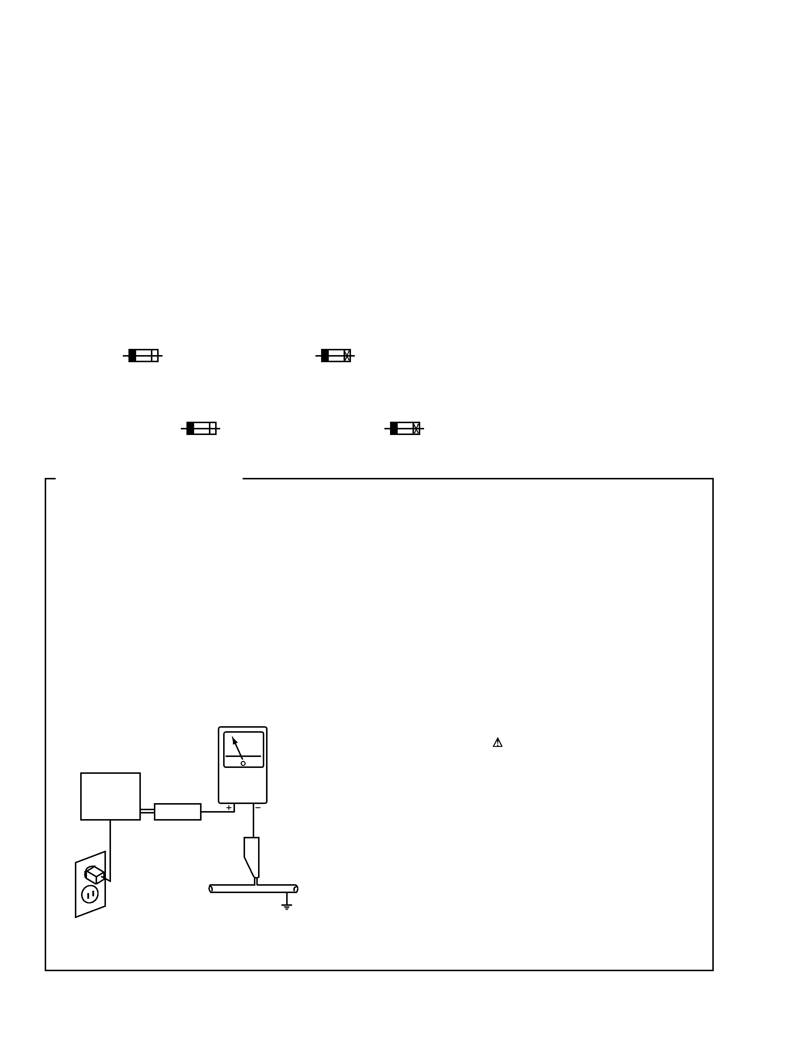
1. SAFETY PRECAUTIONS
The following check should be performed for the
continued protection of the customer and service
technician.
LEAKAGE CURRENT CHECK
Measure leakage current to a known earth ground (water
pipe, conduit, etc.) by connecting a leakage current tester
such as Simpson Model 229-2 or equivalent between the
earth ground and all exposed metal parts of the appliance
(input/output terminals, screwheads, metal overlays, control
shaft, etc.). Plug the AC line cord of the appliance directly
into a 120V AC 60Hz outlet and turn the AC power switch
on. Any current measured must not exceed 0.5mA.
(FOR USA MODEL ONLY)
Leakage
current
tester
Reading should
not be above
0.5mA
Device
under
test
Test all
exposed metal
surfaces
Also test with
plug reversed
(Using AC adapter
plug as required)
Earth
ground
AC Leakage Test
3
A-509R
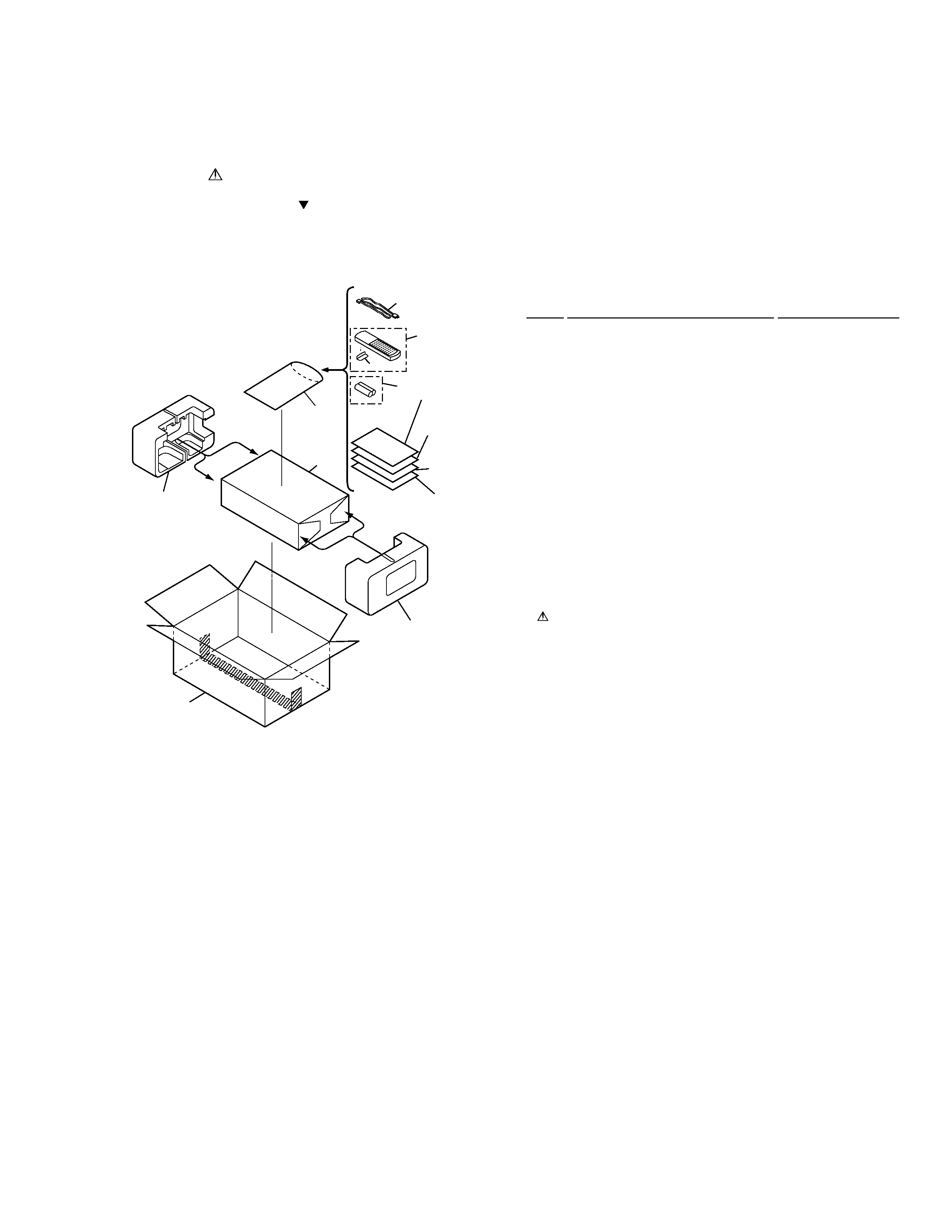
2.1 PACKING
Mark No.
Description
Part No.
2. EXPLODED VIEWS AND PARTS LIST
NOTES:
· Parts marked by "NSP" are generally unavailable because they are not in our Master Spare Parts List.
· The mark found on some component parts indicates the importance of the safety factor of the part.
Therefore, when replacing, be sure to use parts of identical designation.
· Screws adjacent to mark on the product are used for disassembly.
1
Operating Instructions
ARB7238
(English)
2
Operating Instructions
ARC7326
(German)
3
Operating Instructions
ARC7327
(French/Italian/Dutch/Swedish/Spanish/Portuguese)
NSP
4
Warranty Card
ARY7022
5
Remote Control Unit (CU-A018) AXD7187
6
Battery Cover
AZN2249
NSP
7
Dry Cell Battery (R6P,AA)
VEM-013
8
Side Protector L
AHA7127
9
Side Protector R
AHA7128
10
· · · · ·
11
Packing Case
AHD7898
NSP
12
Literature Bag
AHG-117
13
Packing Sheet
AHG1016
14
· · · · ·
15
Power Cord
ADG1154
· PACKING PARTS LIST
6
12
13
Separate
Separate
8
11
9
5
7
15
1
3
2
4
FRONT
4
A-509R
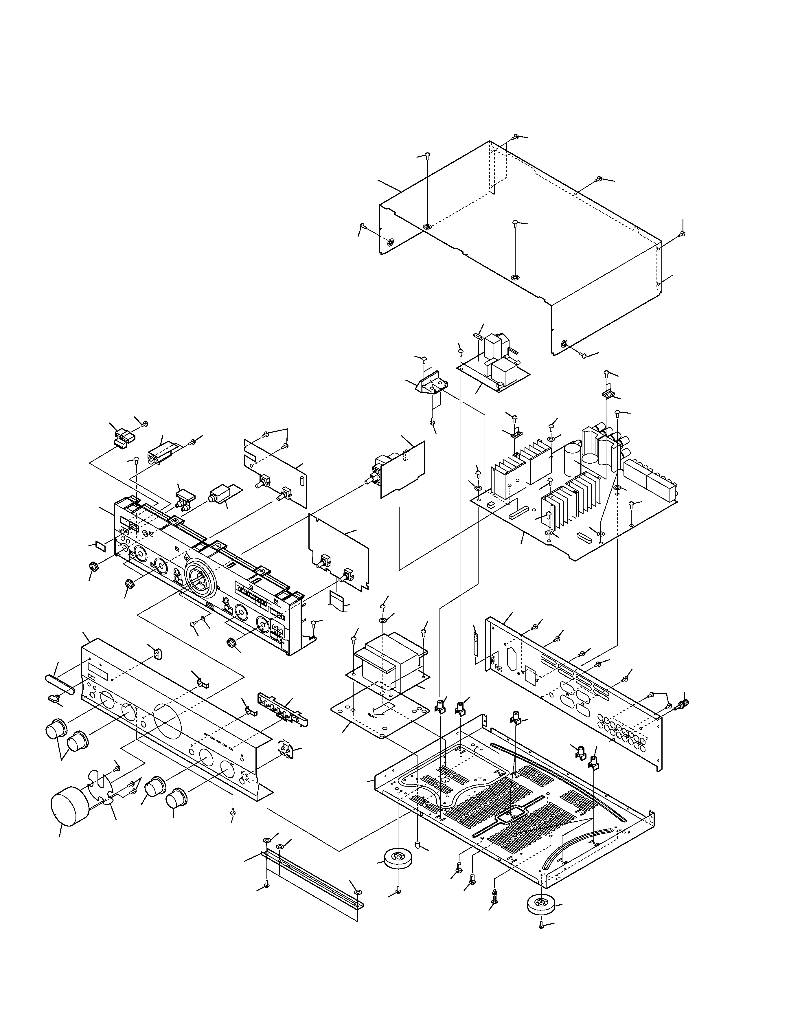
2.2 EXTERIOR
24
41
18
28
37
35
34
43
48
44
5
41
10
49
2
30
31
31
32
38
27
47
27
29
46
14
26
22
21
25
21
26
14
12
23
23
23
23
23
13
20
42
42
42
40
42
39
42
7
15
45
4
8
15
15
15
45
45
45
15
15
45
26
15
16
19
6
42
11
17
17
45
17
43
9
39
39
39
42
42
42
39
36
3
44
44
1
26
24
26
50
52
51
51
51
54
33
16
16
53

5
A-509R
1
FRONT L Assy
AWX7054
2
FRONT R Assy
AWX7718
3
POWER SW Assy
AWX7057
4
AC PRIMARY Assy
AWX7051
NSP
5
HEADPHONE Assy
AWX7052
6
VOLUME Assy
AWX7055
7
AF Assy
AWX7631
8
Fuse (FU1, T2A L250V)
AEK1057
9
Flexible Cable (J1, 21P)
ADD1114
(AF CN202 - FRONT R CN601)
10
Washer
ABE1002
11
Power Transformer (T1)
ATS7202
NSP
12
Chassis
ANA7048
13
Rear Panel
ANC7960
14
Insulator
PNW2766
15
Screw
ABA1018
16
Screw
ABA1050
17
Screw (4
× 12)
ABA1014
18
Nut
ABN-065
NSP
19
PCB Mold
AMR7222
20
Barrier
AEC7072
NSP
21
PCB Holder
AEC7057
22
Stud Cover
AEC7096
NSP
23
PCB Mold
AMR1525
NSP
24
Radiator Plate A
AMR7221
25
Locking Card Spacer
DEC1908
Mark No.
Description
Part No.
Mark No.
Description
Part No.
· EXTERIOR PARTS LIST
26
Screw
BBZ30P080FCC
27
LED Lens
AAK2459
28
IR Filter
AAK7532
29
LED Lens T
AAK7544
30
Name Plate B
PAN1376
31
Rotary Knob A
AAB7148
32
Rotary Knob B
AAB7149
33
Volume Knob
AAB7147
34
Speaker Button
AAD7435
35
Main Power Button
AAD7437
36
Bonnet Case
ANE7185
37
Panel Base
AMB7484
38
Front Panel
ANB7242
39
Screw
BBT30P080FZK
40
Terminal Screw
AKE-031
41
Nut
NK90FUC
42
Screw
BBT30P080FCC
43
Screw
BBZ30P060FCC
44
Screw
BPZ30P080FMC
45
Washer
WG40FCC
46
LED Lens B
AAK7538
47
LED Lens
PNW2019
48
Power Button
AAD7436
49
Screw
BMZ30P080FCU
50
Screw
ABA1193
51
Spacer
ABF7004
NSP
52
Sub Flame
ANG7137
53
Dump Plate
ANG7198
54
Trans Plate
ANG7228