
1
Operating Instructions
STEREO AMPLIFIER
A-109
2
POWER-CORD CAUTION
Handle the power cord by the plug. Do not pull out the plug by
tugging the cord and never touch the power cord when your
hands are wet as this could cause a short circuit or electric
shock. Do not place the unit, a piece of furniture, etc., on the
power cord, or pinch the cord. Never make a knot in the cord
or tie it with other cords. The power cords should be routed
such that they are not likely to be stepped on. A damaged
power cord can cause fire or give you an electrical shock.
Check the power cord once in a while. When you find it
damaged, ask your nearest PIONEER authorized service
center or your dealer for a replacement.
MAINTENANCE OF EXTERNAL SURFACES
÷ Use a polishing cloth or dry cloth to wipe off dust and
dirt.
÷ When the surfaces are very dirty, wipe with a soft cloth
dipped in some neutral cleanser diluted five or six times
with water, and wrung out well, and then wipe again
with a dry cloth. Do not use furniture wax or cleaners.
÷ Never use thinners, benzine, insecticide sprays or other
chemicals on or near this unit, since these will corrode
the surfaces.
Thank you for buying this PIONEER product.
Please read through these operating instructions so you will
know how to operate your model properly. After you have
finished reading the instructions, put them away in a safe
place for future reference.
In some countries or regions, the shape of the power plug and
power outlet may sometimes differ from that shown in the
explanatory drawings. However, the method of connecting
and operating the unit is the same.
WARNING: TO PREVENT FIRE OR SHOCK HAZARD,
DO NOT EXPOSE THIS APPLIANCE TO RAIN OR MOIS-
TURE.
This product complies with the Low Voltage Directive (73/
23/EEC), EMC Directives (89/336/EEC, 92/31/EEC) and CE
Marking Directive (93/68/EEC).
The lightning flash with arrowhead symbol, within an
equilateral triangle, is intended to alert the user to the
presence of uninsulated "dangerous voltage" within the
product's enclosure that may be of sufficient magnitude
to constitute a risk of electric shock to persons.
RISK OF ELECTRIC SHOCK
DO NOT OPEN
CAUTION
IMPORTANT
CAUTION:
TO PREVENT THE RISK OF ELECTRIC SHOCK, DO NOT
REMOVE COVER (OR BACK). NO USER-SERVICEABLE
PARTS INSIDE.
REFER SERVICING TO QUALIFIED
SERVICE PERSONNEL.
The exclamation point within an equilateral triangle is
intended to alert the user to the presence of important
operating and maintenance (servicing) instructions in the
literature accompanying the appliance.
IMPORTANT
FOR USE IN THE UNITED
KINGDOM
The wires in this mains lead are coloured in
accordance with the following code :
Blue
: Neutral
Brown
: Live
If the plug provided is unsuitable for your socket
outlets, the plug must be cut off and a suitable plug
fitted.
Do not connect either wire to the earth terminal of a
three-pin plug.
NOTE
After replacing or changing a fuse, the fuse cover in the
plug must be replaced with a fuse cover which corre-
sponds to the colour of the insert in the base of the plug
or the word that is embossed on the base of the plug, and
the appliance must not be used without a fuse cover. If
lost, replacement fuse covers can be obtained from your
dealer.
Only 5 A fuses approved by B.S.I. or A.S.T.A to B.S.
1362 should be used.
The cut-off plug should be disposed of and must not be
inserted into any 13 amp socket as this can result in electric
shock. The plug or adapter or the distribution panel should
be provided with a 5 amp fuse. As the colours of the wires
in the mains lead of this appliance may not correspond with
the coloured markings identifying the terminals in your plug,
proceed as follows :
The wire which is coloured blue must be connected to the
terminal which is marked with the letter N or coloured black.
The wire which is coloured brown must be connected
to the terminal which is marked with the letter L or coloured
red.
3
CONTENTS
FEATURES
7 High-power Output of 40 W+40 W/8 (DIN)
7 Wide-Range Linear Circuit
This new current feedback circuit assures improved oper-
ating stability for flat output impedance and stable driving
of speakers across the full range of frequencies.
7 Low power consumption design.
7 Complementary capacitor pair.
7 Advanced Direct Energy MOS Power Amp
Pioneer incorporates highest quality amp circuitry featur-
ing Advanced Direct Energy MOS FET devices which can
achieve higher performance. Together with Pioneer's origi-
nal Wide Range Linear Circuit technology they reduce
power consumption while maintaining the power output of
current models.
In terms of performance, this technology contributes to flat
damping factor characteristics across the audio spectrum.
It also allows a wide range and especially ultra high fre-
quencies to be reproduced more accurately and improves
power linearity.
7 Stabilizer
Transformer stabilizer and stabilizer frame (attached to
chassis) deliver powerful sound.
INSTALLATION
LOCATION
Install the unit in a well-ventilated location where it
will not be exposed to high temperatures or humid-
ity.
Do not install the unit in a location which is exposed to direct
rays of the sun, or near hot appliances or radiators. Excessive
heat can adversely affect the cabinet and internal compo-
nents. Installation of the unit in a damp or dusty environment
may also result in a malfunction or an accident.
(Avoid
installation near cookers etc., where the unit may be exposed
to oily smoke, steam or heat.)
Do not install the unit on a tottered stand, nor on an unstable
or inclined surface.
VENTILATION
÷ When installing this unit, make sure to leave space around
the unit for ventilation to improve heat radiation (at least 60
cm at top, 10 cm at rear, and 30 cm at each side). If not
enough space is provided between the unit and walls or
other equipment, heat will build up inside, interfering with
performance or causing malfunctions.
÷ Do not place on a thick carpet, bed, sofa or fabric having a
thick pile. Do not cover with fabric or other covering.
Anything that blocks ventilation will cause internal tem-
perature to rise, which may lead to breakdown or fire
hazard.
FEATURES ......................................................................... 3
INSTALLATION .................................................................. 3
CONNECTIONS .................................................................. 4
PANEL FACILITIES ............................................................. 6
OPERATIONS ..................................................................... 9
TROUBLESHOOTING ...................................................... 11
SPECIFICATIONS ............................................................. 12
4
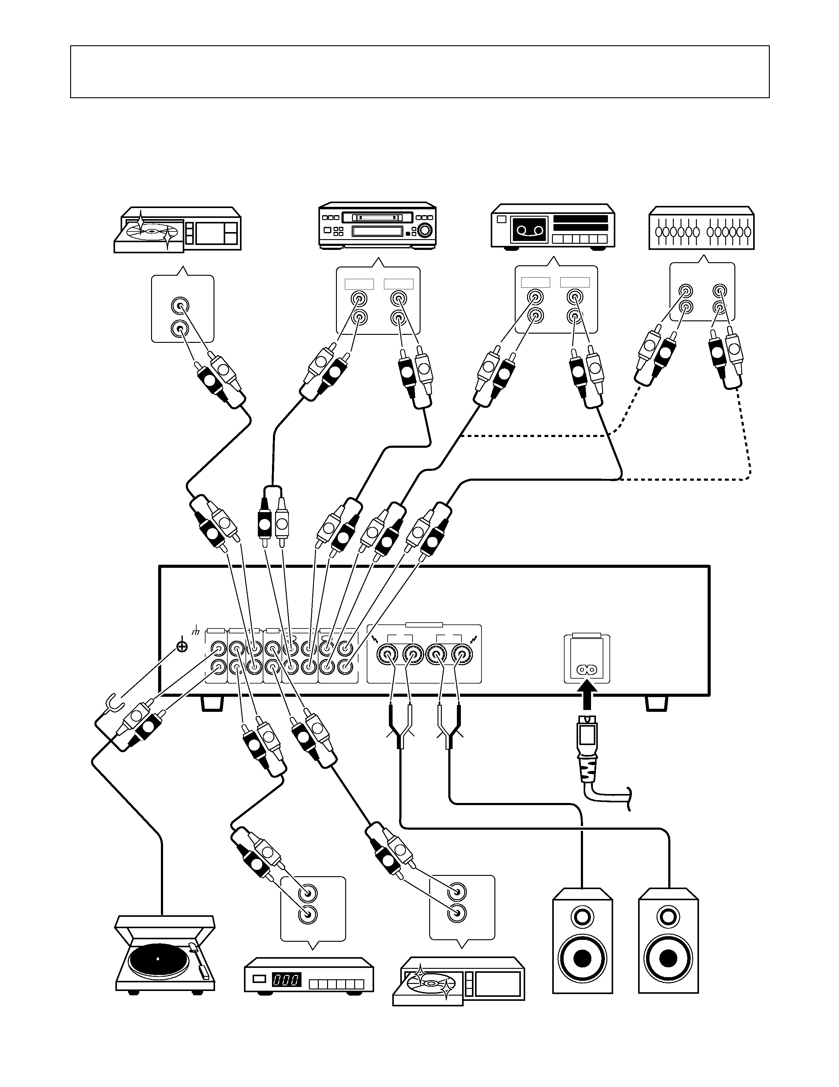
CONNECTIONS
Before making or changing the connections, switch off the power switch and disconnect the power cord from
the AC outlet.
Adaptor component
(graphic equalizer etc.)
Turntable
Tuner
DVD player, VCR, etc.
Speaker
system (Left)
Speaker
system (Right)
CD player
Cassette deck
Cassette deck/
CD recorder/
MD recorder
To an AC wall socket.
SIGNAL
GND
L
R
PHONO
IN
TUNER
IN
CD
IN
LINE
IN
TAPE 1/CD-R/MD
REC
PLAY
REC
PLAY
TAPE 2 MONITOR
OUT
IN
OUT
IN
L
R
RL
SPEAKERS
AC INLET
REC
PLAY
L
R
REC
PLAY
L
R
CD
OUT
L
R
IN
OUT
L
R
FM-AM
OUT
L
R
L
R
L
R
ª
·
ª
·
L
L
L
R
L
R
R
R
L
R
L
R
L
R
L
R
L
R
L
R
L
R
L
R
AUDIO OUT
L
R
L
R
L
R
L
R
MINIDISC
ª
·
ª
·
DVD
5
CONNECTIONS
\
NOTE:
Do not allow any of the cord conductors to protrude from the
terminals or touch any other conductors. Malfunctioning or
breakdowns may occur when conductors come into contact
with each other.
Speaker Impedance
The speaker systems used should have a rated impedance in
the range of 6 - 16
.
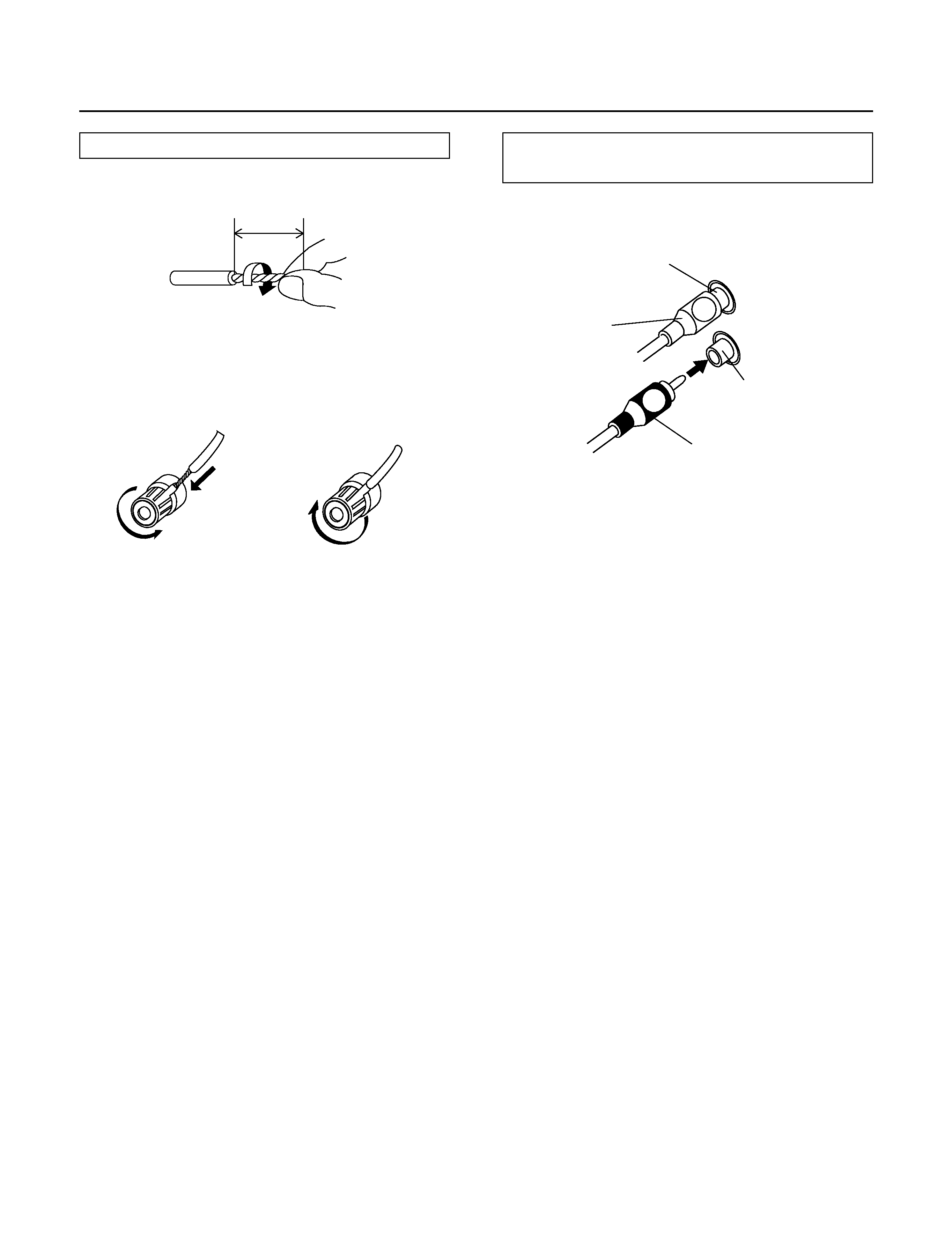
CONNECTING THE SPEAKER CORDS
2. Loosen the knob and insert the wire core into the
terminal hole.
3. Tighten the knob to fix the wire core in place.
10mm
1. Strip off the vinyl covering and twist the tip of the
wire core.
CONNECTING THE INPUT/OUTPUT
CORDS
Connect the white plug to the L (left) channel, and the red plug
to the R (right) channel. Be sure to push the plugs securely.
L
R
Left channel
White plug
Right channel
Red plug
Twist the wire core
2
3
1