Service Manual
Published by MD 0337 Service RCS
Subject to modification
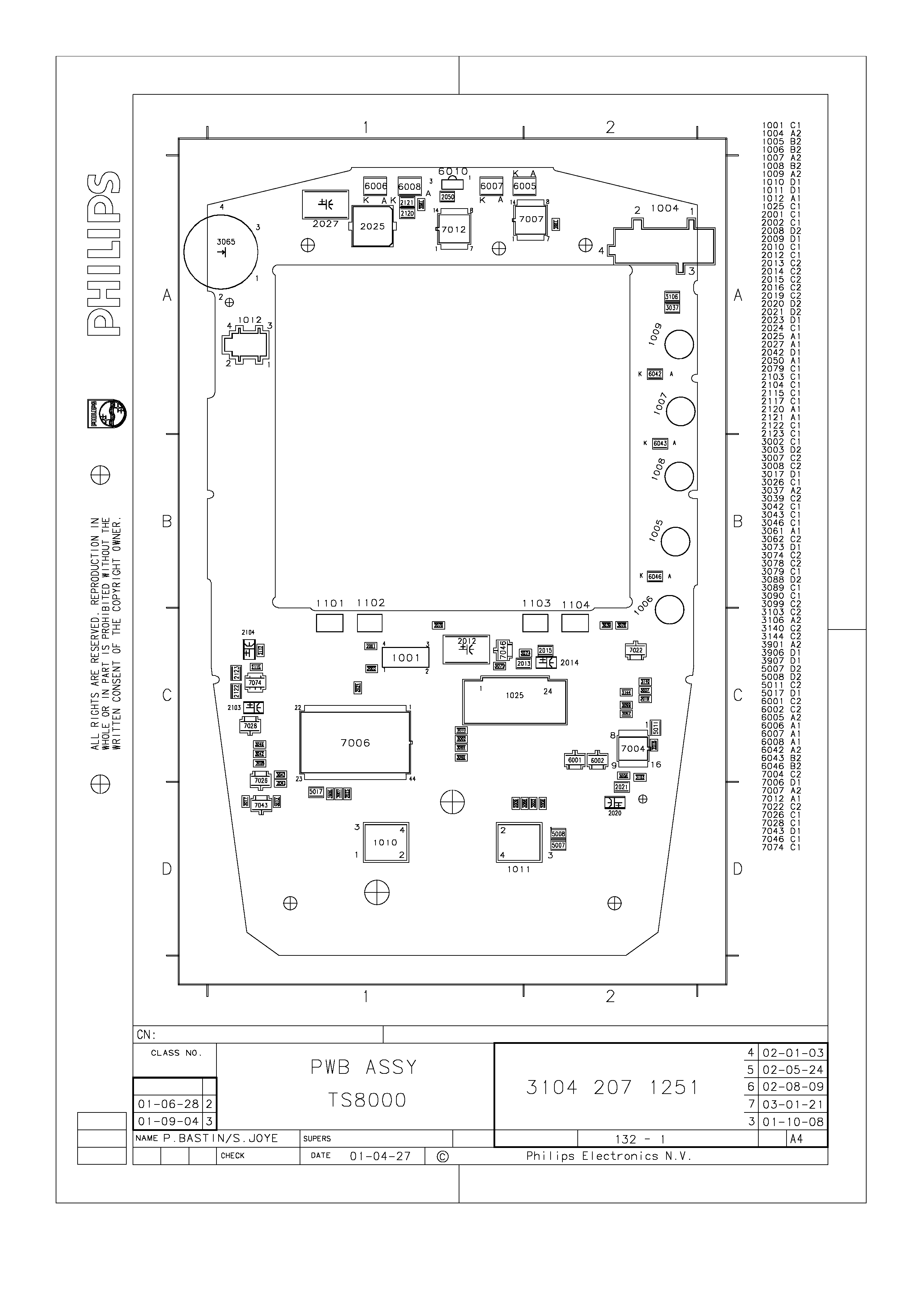
3104 205 5015-1
LCD REMOTE CONTROLLER
TABLE OF CONTENTS
Page
Mechanical Instructions .............................................................
1
USR-5RF
ONKYO
1-1
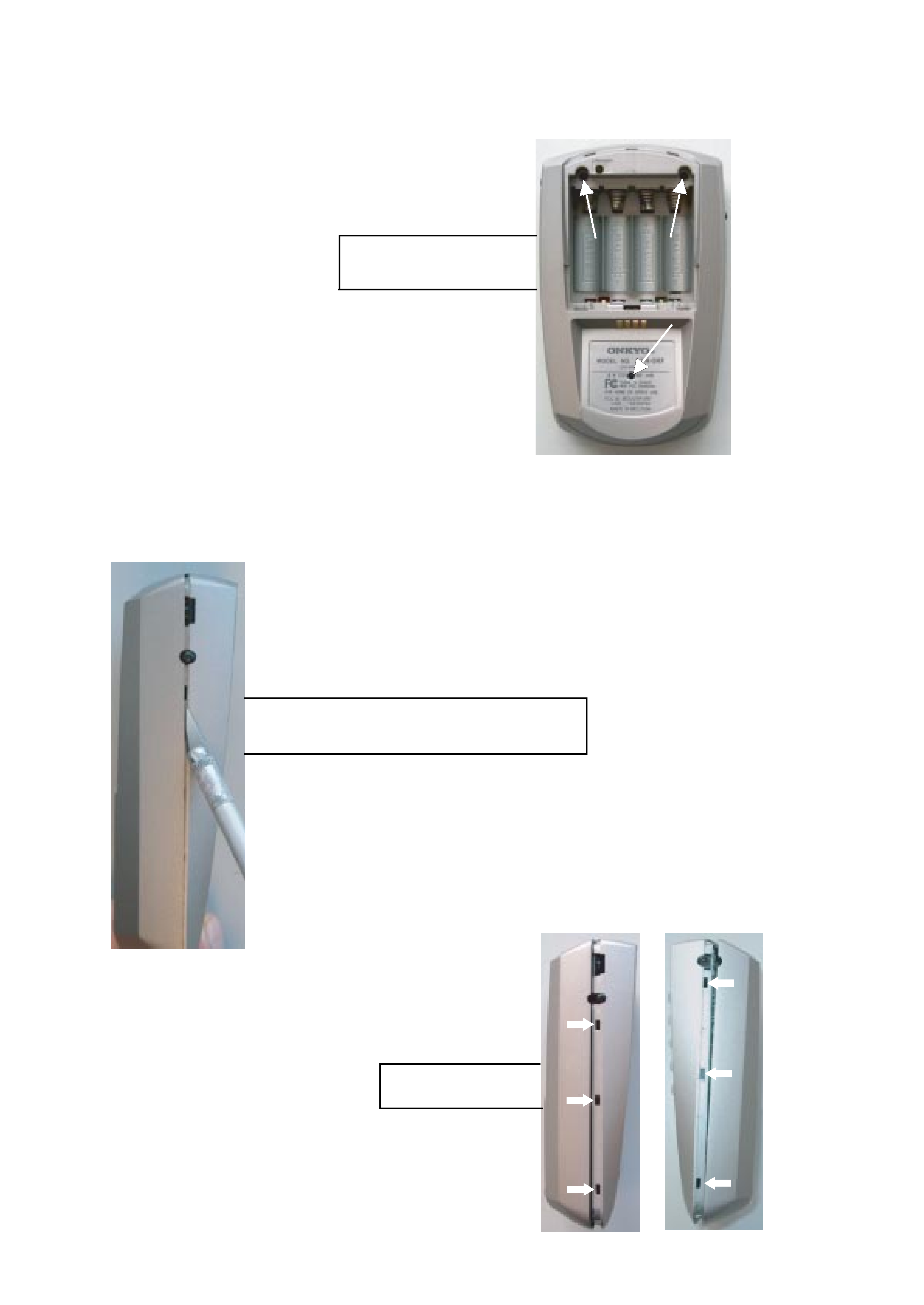
MECHANICAL INSTRUCTIONS
1. Remove battery lid
2. Remove 3 x screw (Torx)
Overview snapholes
Set Disassembly
3. Put a sharp knife between toppart and bottompart
and use this as lever to separate the two parts.
1-2
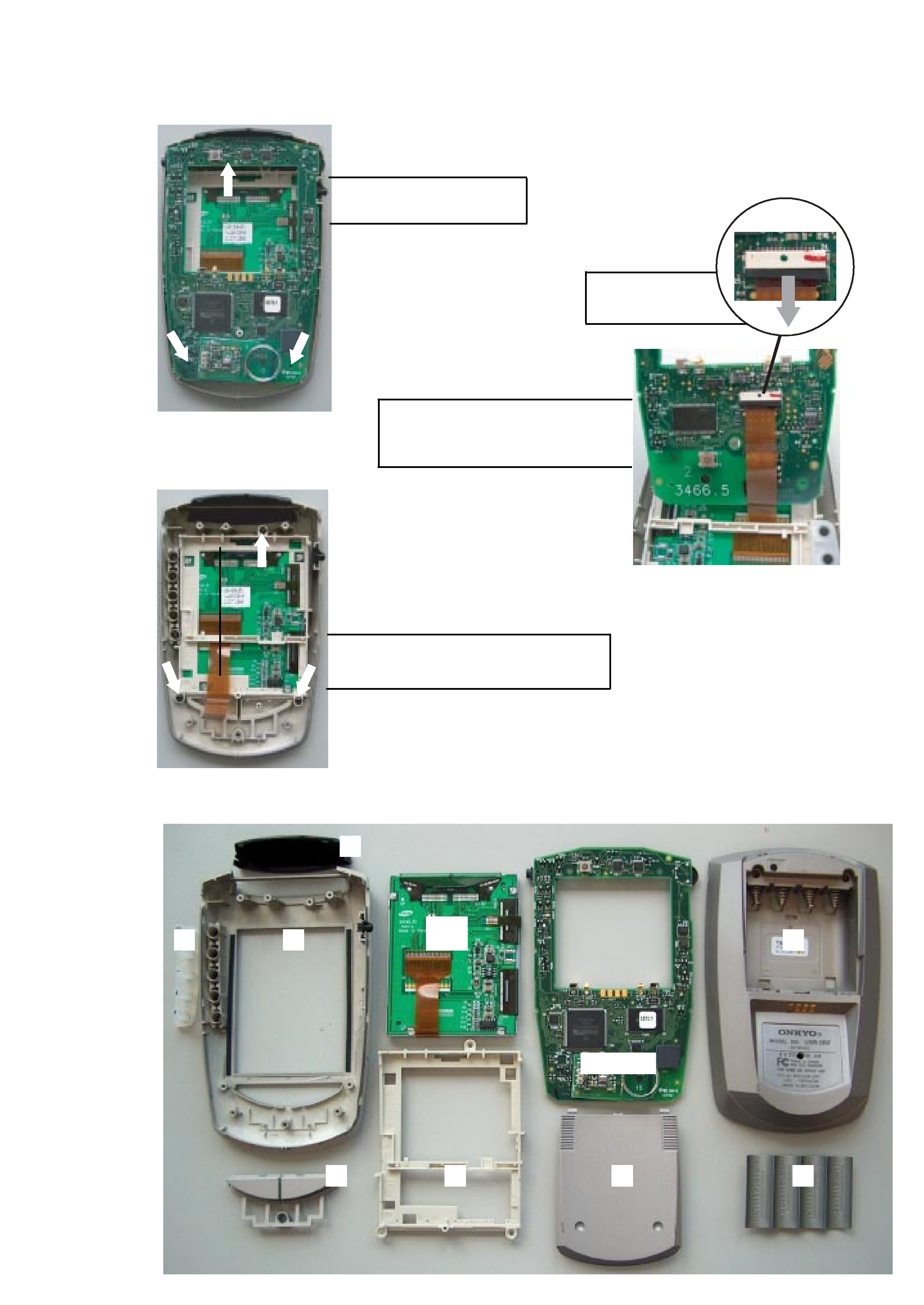
MECHANICAL INSTRUCTIONS
Disassembly LCD & Buttons
1. Remove 3 x screw (Torx)
Overview disassembled parts
4. Remove 3 x screw (Torx)
5. Remove LCD from the Toppart assy.
4
8
2
3
1
Main Board
LCD
Assy
6
7
5
2. Lift up printboard assy and remove
flex cable. For detail see picture 1
3. Remove the printboard assy
Pull flex cable lock
out in direction arrow
Picture 1
For more information:
E-mail: [email protected]
No
Part Description
Part Number
No
Part Description
Part Number
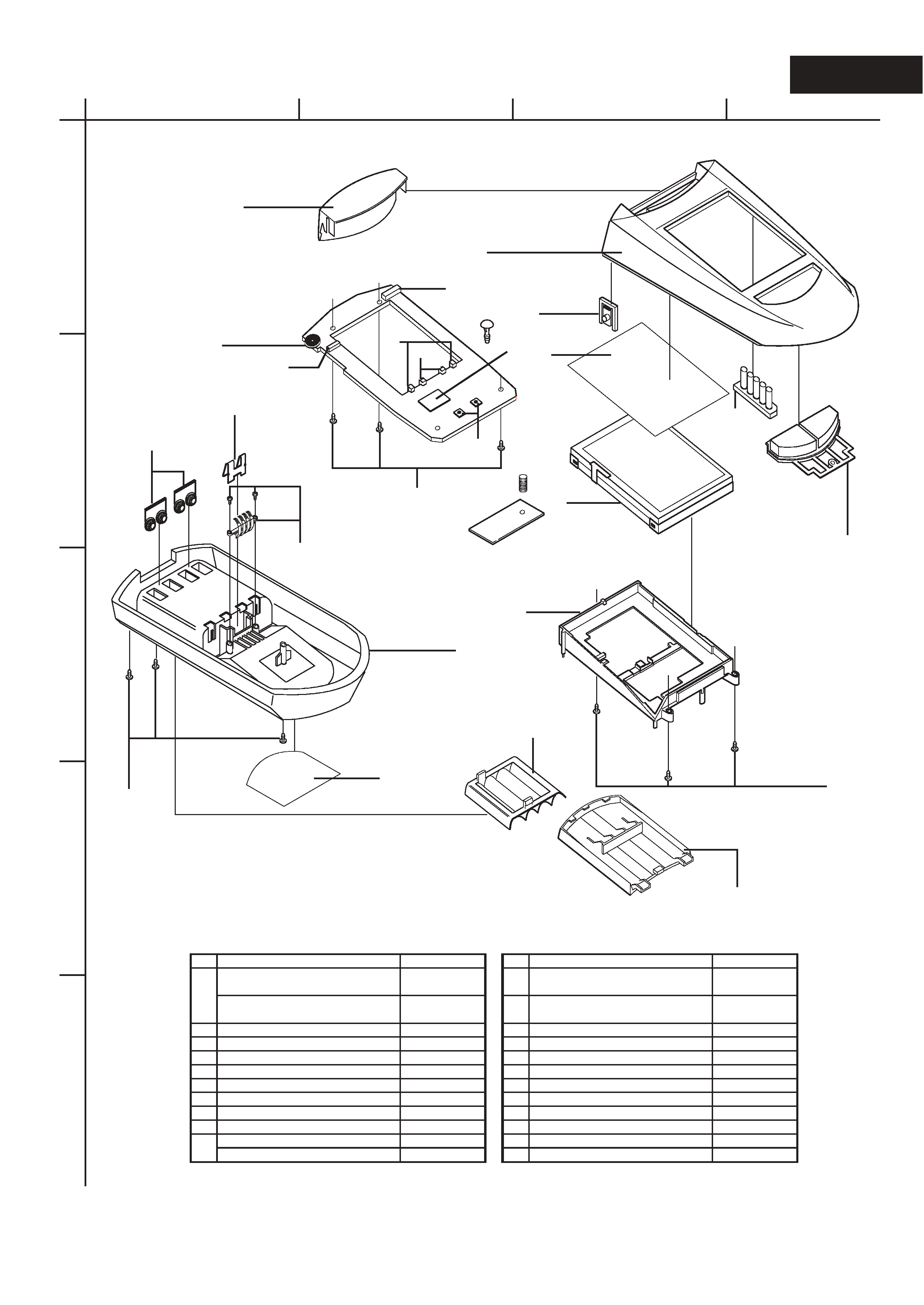
Toppart assy(ONKYO)
(includes hardkeys)
3104 207 78824
11 IC
3104 208 55353
Toppart assy(CHAD)
(includes hardkeys)
3104 207 79334
12 Contrast wheel (pot)
2120 357 90076
2
Bottompart assy
3104 207 78833
13 Serial plug
2422 026 05066
3
Backlight button
3104 204 18731
14 Contact spring
3104 201 23151
4
IR-window
3104 204 18581
15 Contact shunt
3104 201 23141
5
Keymat assy
3104 207 78851
16 Spring +/- (PWB)
3104 201 23163
6
Battery support plate
3104 204 14501
17 Spring loading (PWB)
3104 201 23173
7
LCD
3104 200 51292
18 Screw 2x4mm
3104 200 40031
8
LCD frame
3104 204 18713
19 Screw 2x8mm
3104 200 40061
9
Gasket LCD
3104 204 15983
20 Tact switch mouse/rst
2422 128 02435
Label(ONKYO)
3104 200 04461
21 Tact switch backlight
2422 128 02646
Label(CHAD)
3104 200 04491
22 Batterylid assy
3104 207 78842
1
10
USR-5RF
EXPLODED VIEW
PARTS LIST
A
1
2
3
4
5
BCD
1
2
3
4
5
6
7
8
10
11
12
13
14
15
16
17
18
19
20
21
19
These are included in Bottompart assy
This is included in
Toppart assy
22
9