RC-590M or
RC-591M
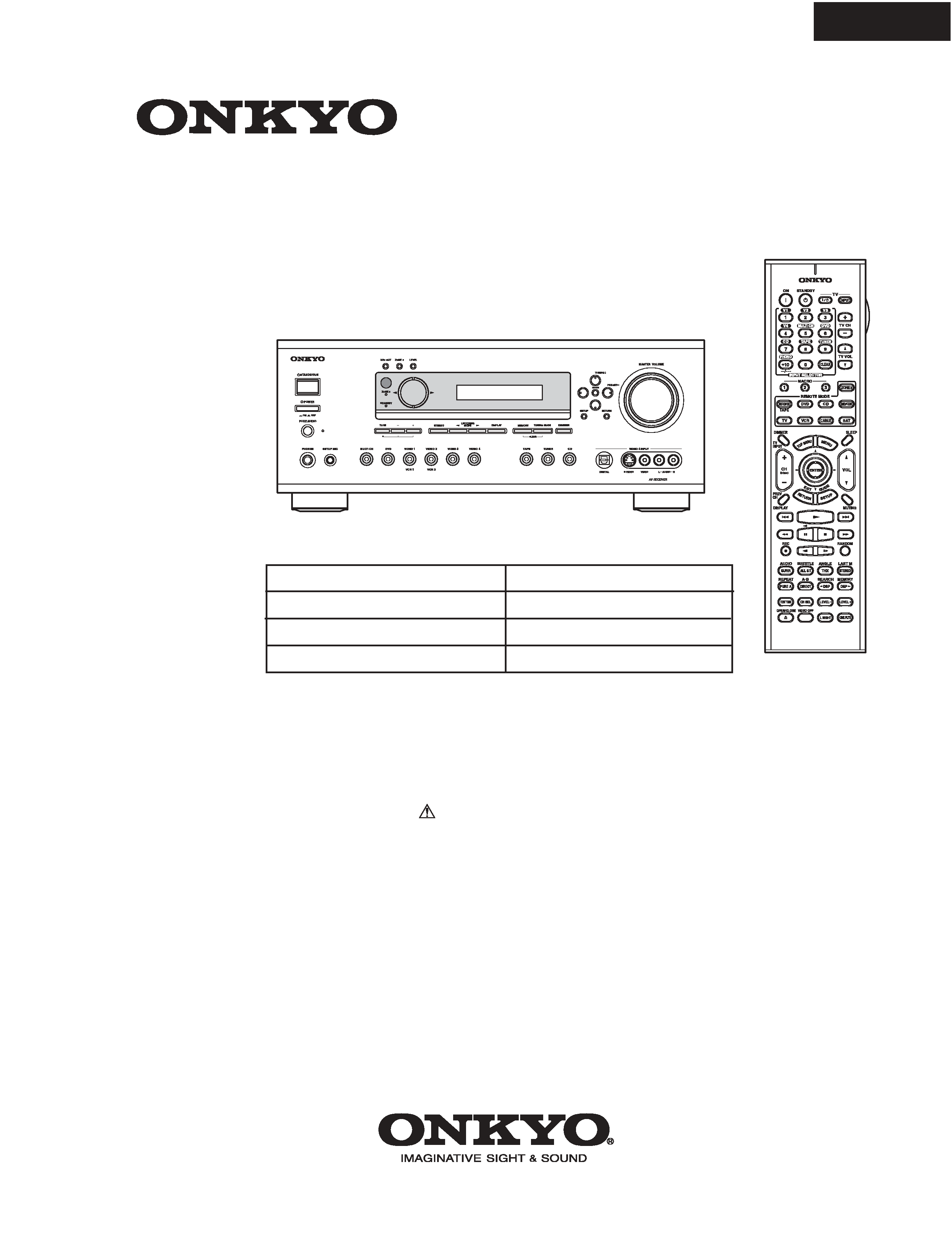
TX-SR602
TX-SR602/E
SERVICE MANUAL
SERVICE MANUAL
Ref. No. 3825
092004
120V AC, 60Hz
230-240V AC, 50Hz
120/220-230V AC, 50/60Hz
220-230V AC, 50Hz
AV RECEIVER
MODEL
TX-SR602/E/8260
Black, Golden and Silver models
BMDD,BMDC,SMDC
BMPP,SMPP,BMPA,SMPA,GMPT
BMWT,GMWT
GMGK,GMGQ,GMGR
SAFETY-RELATED COMPONENT
WARNING!!
THE MARK
FOUND ON SOME COMPONENT
PARTS INDICATES THE CRITICAL FOR RISK OF
FIRE AND ELECTRIC SHOCK.
WHEN REPLACING, BE SURE TO USE PARTS OF
IDENTICAL DESIGNATION.
MAKE LEAKAGE-CURRENT OR RESISTANCE
MEASUREMENTS TO DETERMINE THAT EXPOSED
PARTS ARE ACCEPTABLY INSULATED FROM THE
SUPPLY CIRCUIT BEFORE RETURNING THE
APPLIANCE TO THE CUSTOMER.
TX-SR602/E
SPECIFICATIONS
Amplifier Section
Video Section
Tuner Section
FM
AM
General
Video Inputs
Video Outputs
Audio Inputs
Audio Outputs
Other Jacks
Specifications and features are subject to change without
notice.
Power Output
2 channel driven:
American 85 W + 85 W (8
,20Hz~
20kHz,FTC)
European: 120W + 120 W
(6 ohm ,1kHz,DIN)
Asian: 150 W + 150 W (6 ohm ,1kHz,JEITA)
Dynamic Power
220 W + 220 W (3 ohm,Front)
165 W + 165 W (4 ohm,Front)
100 W + 100 W (8 ohm,Front)
THD (Total Harmonic
Distortion)
0.08 % (Power Rated)
Damping Factor
60 (Front,1kHz,8 ohm)
Input Sensitivity and
Impedance
200 mV/ 47 kohm (LINE)
Output Level and
Impeadance
200 mV/ 470 ohm (REC OUT)
Frequency Response
10 Hz~100 kHz/ +1 dB-3 dB (Direct
mode)
Tone Control
±10 dB, 50 Hz (BASS)
±10 dB, 10 kHz (TREBLE)
SN Ratio
106 dB (LINEIHF-A)
Speaker Impedance
American : 6 ohm~
other :4 ohm~
Input Sensitivity/Output
Level and Impedance
1 Vp-p /75 ohm (Component and S-Video Y)
0.7 Vp-p /75 ohm
ohm
(Component Pb/Cb,Pr/Cr)
0.28 Vp-p /75 ohm (S-Video C)
1 Vp-p /75 ohm (Composite)
Component Video
Frequency Response
5 Hz ~ 50 MHz
Tuning Frequency RangeAmerican: 87.5 MHz~107.9 MHz
Others : 87.5 MHz~108.0 MHz
Usable Sensitivity
Stereo; 17.2 dBf 2 µV(75 ohm IHF)
Mono; 11.2 dBf 1 µV(75 ohm IHF)
S/N Ratio
Stereo; 70 dB (IHF-A)
Mono; 76 dB (IHF-A)
THD
Stereo; 0.3 % (1kHz)
Mono 0.2 % (1kHz)
Frequency Response
30 Hz~15 kHz / ±1 dB
Stereo Separation
45 dB ( 1kHz )
Tuning Frequency RangeAmerican: 530 kHz~1700 kHz
Others: 522 kHz~1611 kHz
Usable Sensitivity
30 µV
S/N Ratio
40 dB
THD
0.70%
Power Supply
American: AC 120 V, 60 Hz
Australian and European: AC 230-240 V,
50 Hz
Others : AC 120/220-230 V, 50/60 Hz
AC 230-240 V, 50Hz
AC 220-230 V, 50/60 Hz
Power Comsumption
American : 8.1A
Others : 700 W
Standby Power
Comsumption
1.0 W
Dimensions(W x H x D) 435 W x 175 H x 430 D mm
17-1/8" W x 6-7/8" H x 16-15/16" D inches
Weight
American, Australian,
European, Singapore
and East southern asian: 13.6 kg
30.0 lbs
Others: 14.8 kg
32.6 lbs
Component Video Input 1,2,3
S-Video Compatible Jack
Input
DVD,VIDEO1,VIDEO2,VIDEO3,
VIDEO4
A/V Input
DVD,VIDEO1,VIDEO2,VIDEO3,
VIDEO4
Component Video
Output
OUT
S-Video Compatible Jack
Output
MONITOR OUT,VIDEO1,VIDEO2
A/V Output
MONITOR OUT,VIDEO1,VIDEO2
Digital Inputs
Optical : 4(American) 3(Others)
Coaxial : 2
Analog Inputs
DVD(MULTICHANNEL),VIDEO1,VID
EO2,VIDEO3,VIDEO4,TAPE,CD
Multichannel Inputs
6
Digital Outputs
Optical : 1
Analog Outputs
TAPE,VIDEO1,VIDEO2
Subwoofer Pre Outputs 1
Speaker Outputs
9
Phones
1
IR Input
1
12V Trigger Out
1
2. To initialize the unit
This device employs a microprocessor to perform various
functions and operations. If interference generated by an external
power supply, radio wave, or other electrical source results in
accident which causes the specified operations and functions to
operate abnormally.
To perform a result, please follow the procedure below.
1.Press and hold down the VIDEO-1 button, then press the
STANDBY/ON button.
2.After "CLEAR" is displayed, the preset memory and each
mode stored in the memory, such as surround, are
initialized and will return to the factory setting.
3. Unplug the power supply cord.
3. Safety-check out
(U.S.A. model only)
After correcting the original service problem, perform the
following safety check before releasing the set to the customer.
Leakage Current Check
Measure leakage current to a known earth ground(water pipe,
conduit, etc.) by connecting a leakage current tester between
the earth ground and exposed metal parts of the appliance
(input/output terminals, screwheads,metal overlays, etc.).
Plug the power supply cord directly into a 120V AC 60 Hz outlet
and turn Standby switch on. Any current meausred must not
exceed 0.5mA.
1. Replacing the fuses
This symbol located near the fuses indicates that the
fuse used is fast operating type. For continued protection against
fire hazard, replace with same type fuse. For fuse rating refer to
the marking adjacent to the symbol.
Ce symbole indique que le fusible utlise est a rapide.
Pour une protection permanente, n'untiliser que fusibles de
meme type. Ce darnier est la qu le present symbol est
appse.
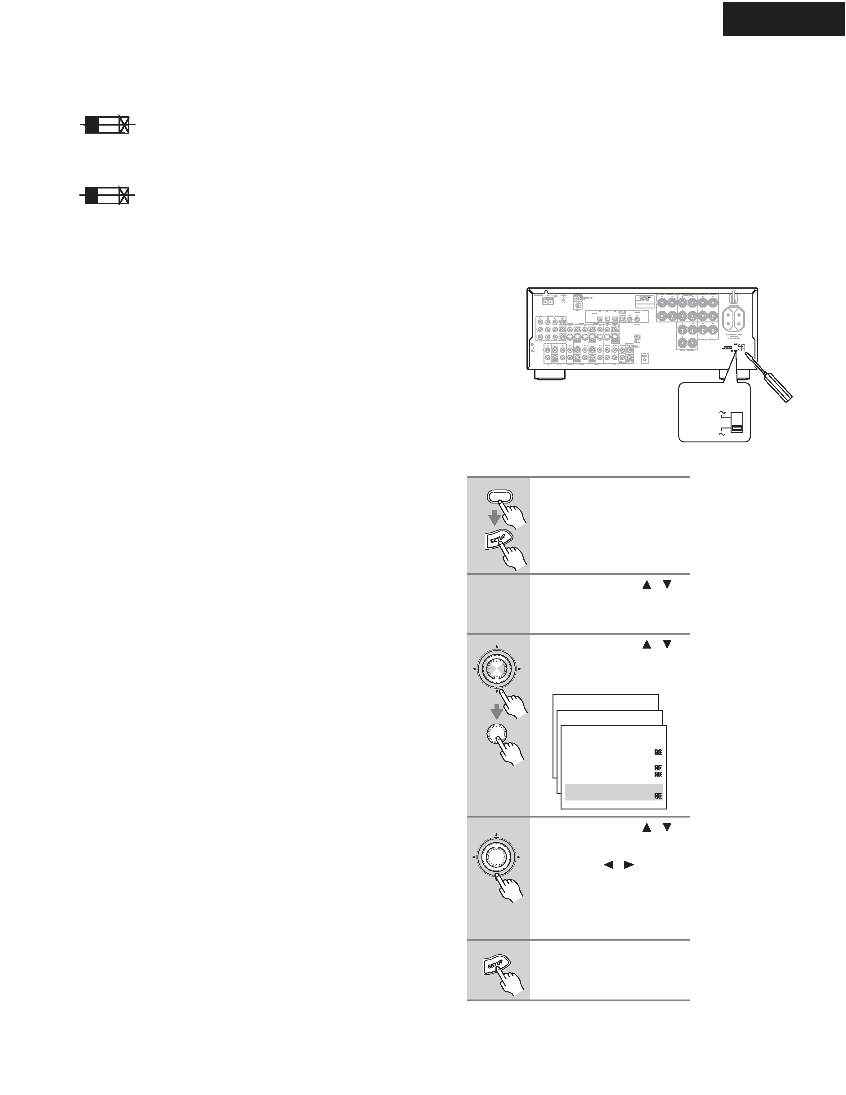
4.Setting the voltage selector (Worldwide models
only)
Worldwide models are equipped with a voltage selector to conform
with local power supplies. Be sure to set this switch to match the
voltage of the power supply in your area before plugging in the unit.
Determine the proper voltage for your area: 220-230 V or 120 V. If
the preset voltage is not correct for your area, insert a screwdriver
into the groove in the switch. Slide the switch all the way to the
upper (120 V) or to the lower (220-230 V), whichever is appropriate.
5.Setting the AM tuning step frequency
(Worldwide models only)
CIRCUIT NO. PART NO.
DESCRIPTION
Note: <D/C>:120V model only
<O>: Other models except 120V model
<WT>: Asian model only for 230V
120V
VOLTAGE
SELECTOR
220-230V
1
Press the [RECEIVER] button fol-
lowed by the [SETUP] button.
The main menu appears onscreen.
2
Use the Up and Down [
]/[
]
buttons to select "1. initial
Setup," and then press [ENTER].
The Initial Setup menu appears.
3
Use the Up and Down [
]/[
]
buttons to select "3. Hardware
Setup," and then press [ENTER].
The Hardware Setup menu appears.
4
Use the Up and Down [
]/[
]
buttons to select "d. AM Fre-
quency Step, and then use the
Left and Right [
]/[
] buttons to
select:
10 kHz: Select if 10 kHz steps are
used in your area.
9 kHz: Select if 9 kHz steps are used
in your area.
5
Press the [SETUP] button.
The setup menu closes.
RECEIVER
ENTER
ENTER
Menu
------------------------
1.Initial Setup
2.Speaker Setup
Advanced Setup
3.Surround Setup
4.Audio Adjust
5.Listening Mode Preset
6.Preference
Basic Setup
1.Initial Setup
------------------------
2.Component Video
3.Hardware Setup
1.Digital Input
1-3.Hardware Setup
------------------------
:Not Activated
b.Sp Impedance Minimum
:6ohms
c.TV Format
:NTSC
d.AM Frequency Step
: 9kHz
a.Powered Zone2
ENTER
F6901,F6902
252301 or
12A-TUL-250V or
252196
12A-UL/T-314,Fuse
F901
252199
10A-UL,Fuse <D/C/WT>
F902
252078,
5A-SE-EAK,
252244 or
5A-SE-TL250V or
252278
5A-SE-TL250V,Fuse <O>
F903
252164 or
5A-UL/T-237 or
252258
5A-T/UL-ST2,Fuse <D/C>
252075,
2.5A-SE-EAK,
252241 or
2.5A-SE-TL250V or
252275
2.5A-SE-TL250V,Fuse <O>
F9501
252160 or
2.5A-UL/T-237 or
252254
2.5A-T/UL-ST2,Fuse <D/C>
252075,
2.5A-SE-EAK,
252241 or
2.5A-SE-TL250V or
252275
2.5A-SE-TL250V,Fuse <O>
TX-SR602/E
SERVICE PROCEDURES
A038
A039
A187
A186
A031
A059
A031
A046
A091
A031
A031
A036
A031
U33
A031
A031
A042
A033
A037
A031
A211
A031
A101
Q6050
Q6055
Q6064
Q6066
A031
Q6050A
A151
A031
A031
A031
A031
T901
A070
A196
A057
E800
A056
A041
A018
A011
A006
A001
A031
A176
A017
A026
A051
A206
A201
A196
A029
A050
A013
A206
A201
A216
A101
Q6050A
A031
A031
A081
U2
U27
U36
U18
U21
U22
U12
U32
U26
U30
U31
U29
U6
U19
U5
U16
U17
U7
U13
U4
U3
U1
P761
P7502
P6931
P7501
F903
F901
F9501
F6902
F6901
P901
A009
A002
U10
U9
A005
A012
A171
U14
U23
A016
F902
A045
A021
A043
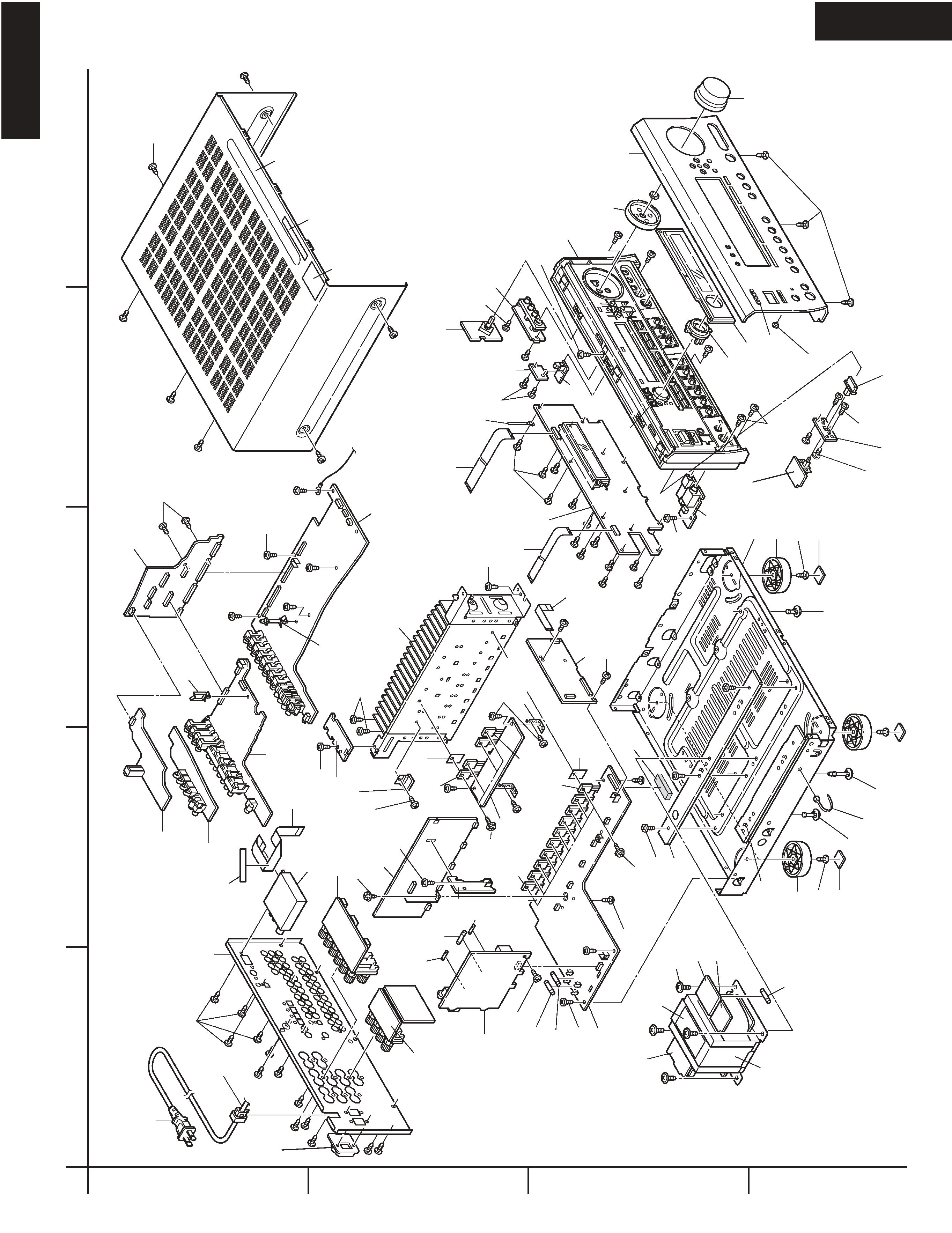
TX-SR602/E
EXPLODED VIEW
TX-SR602/E
A
1
2
3
4
BCD
E
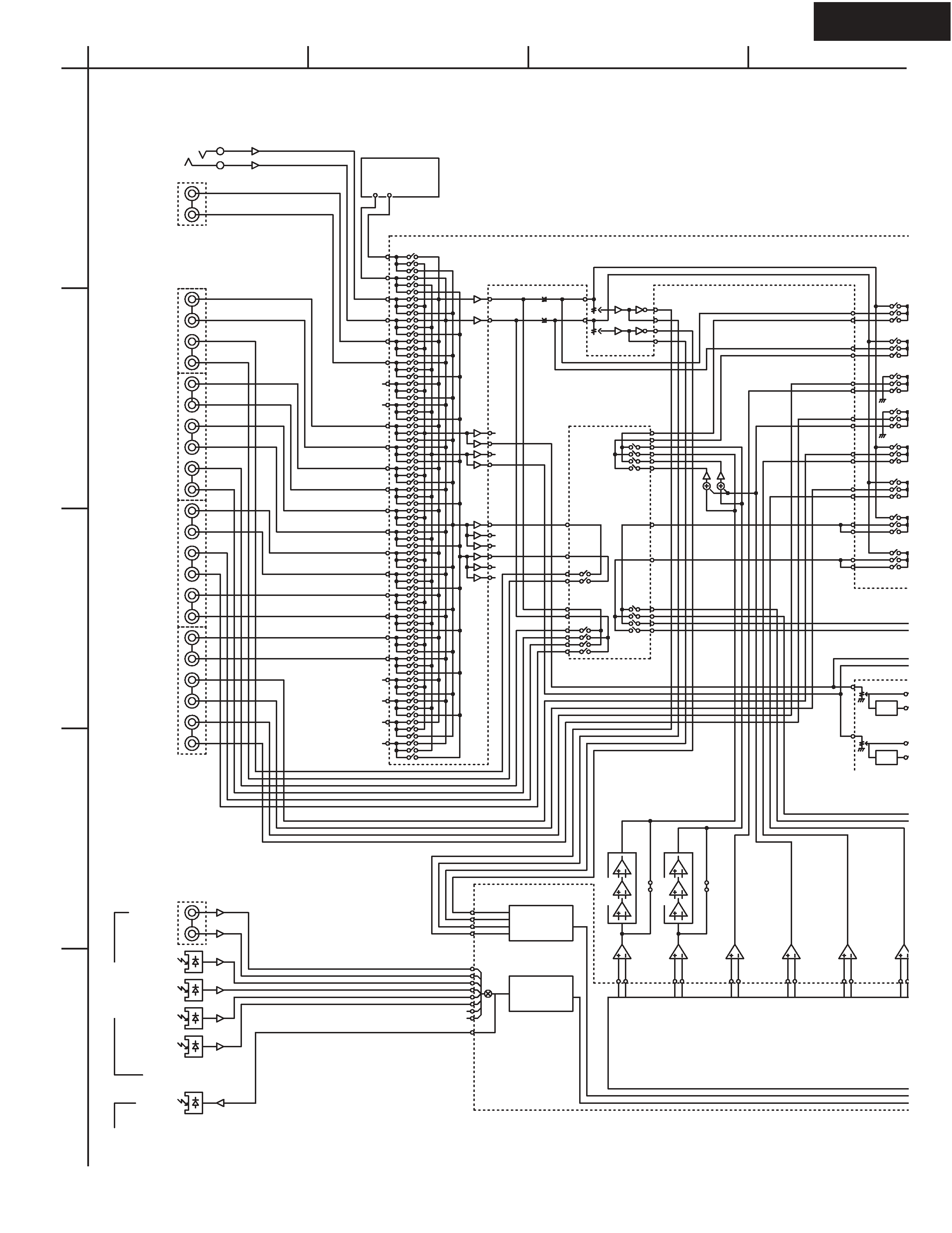
TX-SR602/E
BLOCK DIAGRAM Amplifier section
A
1
2
3
4
5
BCD
TAPE_OUT_R
TAPE_OUT_L
V2_OUT_L
V2_OUT_R
V1_OUT_L
V1_OUT_R
Z2_R
Z2_L
MIX_R
MIX_L
SOURCE_L
SOURCE_R
RECOUT_L
RECOUT_R
MCH_SR
MCH_SL
MCH_SW
MCH_CT
ADLT+
ADRT+
ADLT-
ADRT-
ADRT-
ADRT+
ADLT+
ADLT-
RX0
RX1
RX2
RX3
RX4
RX5
TX
RX6
DAC_FL
DAC_CT
DAC_SW
DAC_FR
DAC_SR
DAC_SBR
DAC_SBL
DAC_SL
VOLIN_SBR
VOLIN_SBL
MIC
TUNER PACK
VIDEO4
NJW1157
CD
TAPE OUT
TAPE IN
VIDEO3 IN
VIDEO2 OUT
VIDEO2 IN
VIDEO1 OUT
VIDEO1 IN
DVD
MSL/MSR
MC/MSW
COAX 1
COAX 2
Digital
Input
OPT FRNT
OPT1
OPT2
OPT3
OPT
Digital Output
-6dB
-6dB
+9.7dB
TC9162
DIR
2ch ADC
CS42518
8ch DAC
+6dB
VLSC
LPF
TONE
TONE
MIC AMP
+6dB
LPF
LPF
LPF
LPF
VLSC
LPF
non
VLSC
non
VLSC
52
53
54
55
56
57
58
59
60
61
62
63
64
65
66
67
68
69
70
71
73
73
51
74
41
43
23
25
22
24
26
21
27
29
28
30
44
42
46
45
48
47
93
92
91
95
90
89
88
86
85
84
83
87
82
81
80
94
9
8
12
17
10
19
20
21
11
18
4
25
3
26
2
27
22
7
23
6
5
24
16
15
14
13
49
48
43
42
47
46
45
44
50
37
36
17
19
35
34
32
33
31
30
28
29
26
27
+
+
A
A
A
A
VLSC:European model only