TX-SR703/E
SERVICE MANUAL
SERVICE MANUAL
Ref. No. 3910
102005
120V AC, 60Hz
230-240V AC, 50Hz
120/220-230V AC, 50/60Hz
220-230V AC, 50Hz
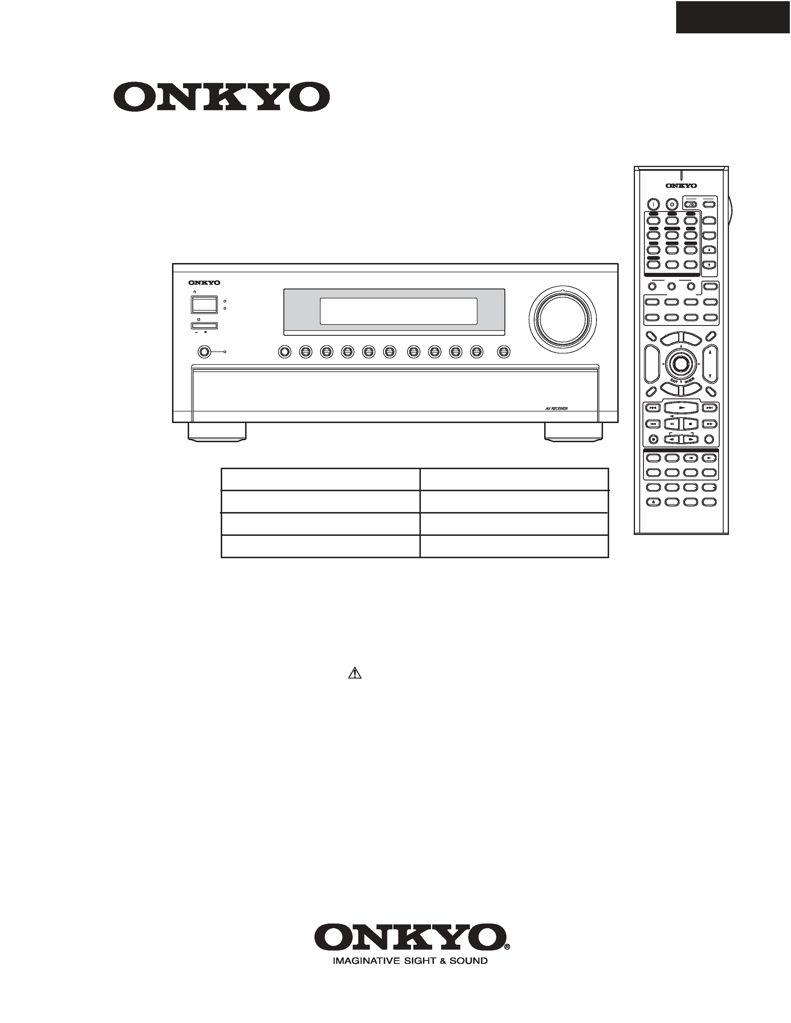
AV RECEIVER
MODEL
TX-SR703/E
Black, Golden and Silver models
BMDD,BMDC,SMDC
BMPP,SMPP,BMPA,GMPA
GMWT
GMGK,GMGQ,GMGR
SAFETY-RELATED COMPONENT
WARNING!!
THE MARK
FOUND ON SOME COMPONENT
PARTS INDICATES THE CRITICAL FOR RISK OF
FIRE AND ELECTRIC SHOCK.
WHEN REPLACING, BE SURE TO USE PARTS OF
IDENTICAL DESIGNATION.
MAKE LEAKAGE-CURRENT OR RESISTANCE
MEASUREMENTS TO DETERMINE THAT EXPOSED
PARTS ARE ACCEPTABLY INSULATED FROM THE
SUPPLY CIRCUIT BEFORE RETURNING THE
APPLIANCE TO THE CUSTOMER.
RC-620M
THX
10
--/---
11
12
REMOTE MODE
HDD
RECEIVER
TAPE/AMP
DVD
CD
ZONE2
SAT
TV
VCR
CABLE
MD
CDR
STEREO
SURR
DIRECT
SUBTITLE
AUDIO
ALLST
PLAY MODE
VIDEO OFF
REPEAT
RANDOM
REC
PLAYLIST
OPEN/CLOSE
Re-EQ
+
-
TV CH
TV VOL
ENTER
SET
UP
TO
P M
ENU
MEN
U
VOL
+
-
CH
DISPLAY
PREV
CH
DIMMER
SLEEP
MUTING
LISTENING MODE
INPUT SELECTOR
3
2
MACRO
1
+10
0
CLEAR
12
3
45
6
78
9
INPUT
I
ON
STANDBY
TV
CD
V1
V2
V3
MULTI CH
DVD
TUNER
PHONO
DISC
ALBUM
V4
TAPE
PURE A
TEST TONE
CH SEL
LEVEL
LEVEL
L NIGHT
RE
TURN
RC-620M
STANDBY/ON
STANDBY
MASTER VOLUME
PHONO
ZONE 2
DISPLAY
PURE AUDIO
TUNER
TAPE
VIDEO 4
VIDEO 3
VIDEO 2
VIDEO 1
DVD
MULTI CH
CD
OFF
ON
POWER
PUSH TO OPEN
TX-SR703
TX-SR703/E
SPECIFICATIONS
Amplifier Section
Video Section
Tuner Section
FM
AM
General
Video Inputs
Video Outputs
Audio Inputs
Audio Outputs
Specifications and features are subject to change without
notice.
Power Output
2 channels driven:
North American: 100 W + 100 W
(8
, 20 Hz-20 kHz, FTC)
European: 130 W + 130 W
(6
, 1 kHz, DIN)
Others: 160 W + 160 W
(6
, 1 kHz, JEITA)
Dynamic Power
230 W + 230 W (3
, Front)
170 W + 170 W (4
, Front)
115 W + 115 W (8
, Front)
THD (Total Harmonic
Distortion)
0.08% (Power Rated)
Damping Factor
60 (Front, 1 kHz, 8 )
Input Sensitivity and
Impedance
200 mV/ 47 k
(LINE)
2.5 mV/47 k
(PHONO MM)
Output Level and
Impedance
200 mV/ 470
(REC OUT)
Phono Overload
70 mV (MM 1 kHz, 0.5%)
Frequency Response
10 Hz-100 kHz/ +1 dB-3 dB (LINE)
Tone Control
±10 dB, 50 Hz (BASS)
±10 dB, 20 kHz (TREBLE)
Signal to Noise Ratio
106 dB (LINE, IHF-A)
80 dB (PHONO, IHF-A)
Speaker Impedance
4
min. or 6
Input Sensitivity/Output
Level and Impedance
1 Vp-p /75
(Component and S-Video Y)
0.7 Vp-p /75
(Component Pb/Cb,Pr/Cr)
0.28 Vp-p /75
(S-Video C)
1 Vp-p /75
(Composite)
Component Video
Frequency Response
5 Hz - 100 MHz
Tuning Frequency
Range
North American: 87.5 MHz- 107.9 MHz
Other: 87.5 MHz-108.0 MHz
Usable Sensitivity
Stereo: 22.2 dBf (75
IHF)
Mono: 15.2 dBf (75
IHF)
Signal to Noise Ratio
Stereo: 67 dB (IHF-A)
Mono: 73 dB (IHF-A)
THD
Stereo: 0.5% (1 kHz)
Mono:0.3% (1 kHz)
Frequency Response
30 Hz-15 kHz / ±1 dB
Stereo Separation
40 dB (1 kHz)
Tuning Frequency
Range
North American: 530 kHz-1710 kHz
European: 522 kHz-1611 kHz
Asian: 530/522 kHz-1710/1611 kHz
Usable Sensitivity
300 µV/m
Signal to Noise Ratio
40 dB
THD
0.70%
Power Supply
North American: AC 120 V, 60 Hz
Australian and European:
AC 230-240 V, 50 Hz
Others: AC 120/220-240 V, 50/60 Hz
AC 230-240 V, 50Hz
AC 220-230 V, 50/60 Hz
Power Consumption
North American: 7.5 A
Others: 680 W
Standby Power
Consumption
North American: 0.1 W
Australian and European: 0.2 W
Others: 0.5 W
Dimensions
(W
× H × D)
435
× 173.5 × 430 mm
17-1/8"
× 6-13/16" × 16-15/16"
Weight
North American: 13.3 kg
29.3 lbs.
European: 13.5 kg
29.8 lbs.
Others: 13.3 kg
29.3 lbs.
Component
IN1, IN2, IN3
S-Video
DVD, VIDEO1, VIDEO2, VIDEO3,
VIDEO4
Composite
DVD, VIDEO1, VIDEO2, VIDEO3,
VIDEO4
Component
OUT
S-Video
MONITOR OUT, VIDEO1, VIDEO2
Composite
MONITOR OUT, VIDEO1, VIDEO2
Digital Inputs
Optical: 5 (1 on Front Panel)
Coaxial: 2
Analog Inputs
DVD (MULTICHANNEL), VIDEO1,
VIDEO2, VIDEO3, VIDEO4, TAPE, CD,
PHONO
Multichannel Input
7.1 ch (DVD)
Digital Output
Optical: 1
Analog Outputs
TAPE, VIDEO1, VIDEO2, ZONE2
Multichannel Pre
Outputs
7.1 ch
Speaker Outputs
L, R, C, SL, SR, SBL, SBR
ZONE2 (L, R)
Phones
1
RS232
1 (Other than North American and
Australian)
IR Input/Output
1/0
12 V Trigger Out
ZONE2
min.
TX-SR803/E
SERVICE PROCEDURES
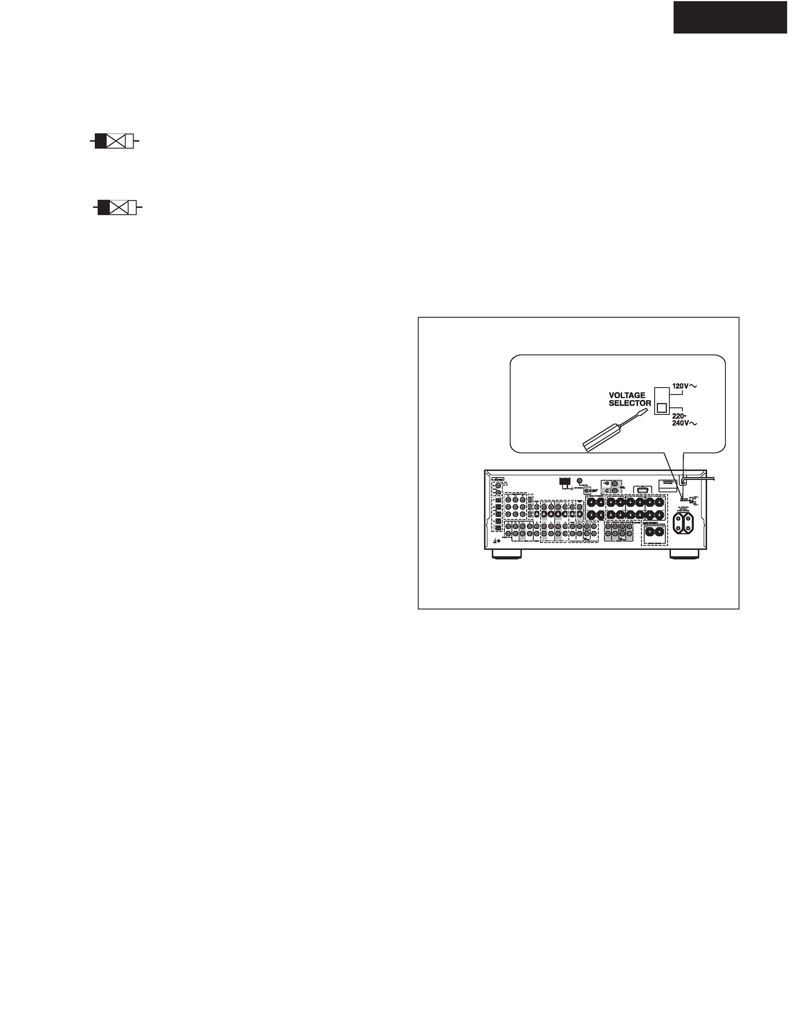
Worldwide models are equipped with a voltage selector to conform with
local power supplies. Be sure to set this switch to match the voltage of
the power supply in your area before plugging in the unit.
1. Determine the proper voltage for your area: 220-240 V or
120 V.
2. If the preset voltage is not correct for your area, insert a screw-
driver into the groove in the switch. Slide the switch all the way
to the right (120 V) or to the left (220-240 V), whichever is
appropriate.
4.Setting the Voltage selector (Worldwide models
only)
1. Replacing the fuses
This symbol located near the fuses indicates that the
fuse used is fast operating type. For continued protection against
fire hazard, replace with same type fuse. For fuse rating refer to
the marking adjacent to the symbol.
Ce symbole indique que le fusible utlise est a rapide.
Pour une protection permanente, n'untiliser que fusibles de
meme type. Ce darnier est la qu le present symbol est
appse.
CIRCUIT NO.
PART NO.
DESCRIPTION
2. To initialize the unit
This device employs a microprocessor to perform various
functions and operations. If interference generated by an external
power supply, radio wave, or other electrical source results in
accident which causes the specified operations and functions to
operate abnormally.
To perform a result, please follow the procedure below.
1.Press and hold down the VIDEO-1 button, then press the
STANDBY button.
2.After "Clear" is displayed, the preset memory and each
mode stored in the memory, such as surround, are
initialized and will return to the factory setting.
5. Changing the AM band step
With the exception of the worldwide models, a tuning step selector
switch is not provided. When you change the band step, change
the parts as shown below.
To 10kHz
To 9kHz
R714
Open
10 k
Note: <D>:120V model only
<P>: European model only
<Q/R/K>: 230V model only
<T>:Worldwide model only
<A>: Australian model only
3. Safety-check out
(U.S.A. model only)
After correcting the original service problem, perform the
following safety check before releasing the set to the customer.
Leakage Current Check
Measure leakage current to a known earth ground(water pipe,
conduit, etc.) by connecting a leakage current tester between
the earth ground and exposed metal parts of the appliance
(input/output terminals, screwheads,metal overlays, etc.).
TX-SR703/E
F6901,F6902
252301GR
12A-TUL-250V,Fuse
F901
252079GR
6.3A-SE-EAK,Fuse <P/A/Q/R/K>
252330GR
10A-UL/T-233, Fuse <D/C>
F902
252079GR
6.3A-SE-EAK Fuse <T>
F903
252075GR
2.5A-SE-EAK,Fuse <P/A/Q/R/K>
252326GR
5A-UL/T-233,Fuse <D/C>
F931,F932
252073GR
1.6A-SE-EAK,Fuse
F951,F952
252079GR
6.3A-SE-EAK,Fuse
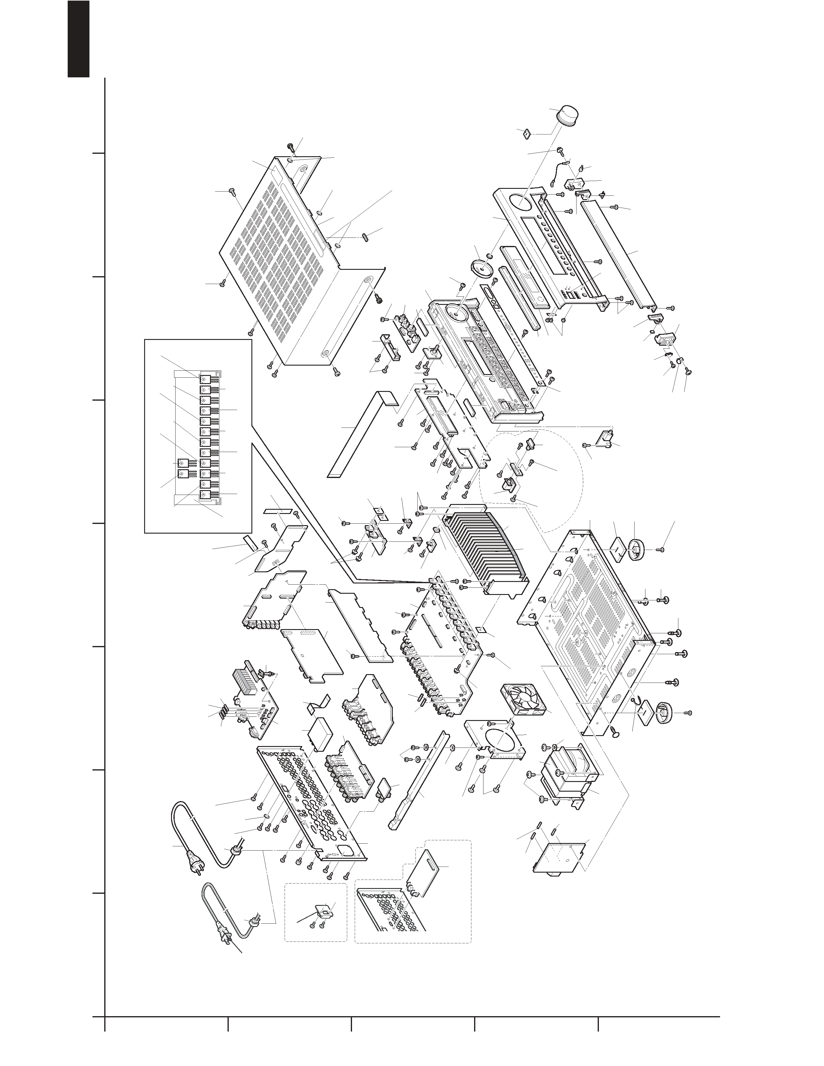
TX-SR703/E
EXPLODED VIEW
Q6050
Q6051
Q6053
Q6055
Q6052
Q6054
Q6060
Q6061
Q6063
Q6066
Q6065
Q6062
Q6064
Q6056
A080
A040
A035
A025
A022
A036
A029
A010
A019
A412
A009
A032
A411
A027
A039
A030
A038
A031
A033
A023
A410
A005
A001
A003
A002
A418
U047
U063
A080
A105
A052
A060
T901
A065
A051
F6901
F901
F902
F903
F6902
A077
A090
A059
A401
A405
A404
A403
P691
P7534
U033
U053
U05
U046
U044
U04
U02
U06
U062
U064
U045
U03
U032
U11
U042
P701
P901
F951
F952
F932
F931
U043
U052
Q6050a
x 12 sheets
Q6050a
x 2 sheets
A081
A100
x 4 pcs.
A037
x 5 pcs.
A003
x 5 pcs.
A003
x 2 pcs.
A416
x 2 pcs.
A105
x 2 pcs.
A056
x 4 pcs.
A105
x 3 pcs.
A105
x 2 pcs.
A105
x 3 pcs.
A082
x 2 pcs.
A105
x 3 pcs.
A105
x 4 pcs.
A087
x 2 pcs.
A082
x 12 pcs.
A105
x 2 pcs.
A057
x 2 pcs.
A402
x 44 pcs.
A062
x 4 pcs.
A417
x 2 pcs.
A054
x 3 pcs.
A053
x 3 pcs.
A055
x 11 pcs.
A003
x 3 pcs.
A003
x 15 pcs.
A011
x 3 pcs.
A037
x 2 pcs.
A101
x 4 pcs.
A095
A099
A096
A409
x 3 pcs.
A420
A406
R model
D/C models
U08
A050
A119
x 4 pcs.
A111
x 4 pcs.
A114
x 4 pcs.
A063
x 3 pcs.
A081
A081
x 4 pcs.
A044
A020
A020
P901
A110
A405
P/T/R/K
models
A089
A
1
2
3
4
5
B
C
DE
FG
H

TX-SR703/E
EXPLODED VIEW-PARTS LIST
NOTE: THE COMPONENTS IDENTIFIED BY MARK !
ARE CRITICAL FOR RISK OF FIRE AND
ELECTRIC SHOCK. REPLACE ONLY WITH
PART NUMBER SPECIFIED.
CAUTION: Replacement for transistor of mark *, if necessary
must be made from the same beta group (hFE) as
the original type.
NOTE: <B>: Black model only <G>: Golden model only <S>: Silver model only
<D>: USA model only <P>: European model only <A>:Australian model only
<T>: Worldwide model only <R>: Chinese model only <C>:Canadian model only
<K>:Korean model only <Q>:Hongkong model only
<NSP>: No spare part
REF.NO.
PART NO.
DESCRIPTION
A001
27111421B
Front bracket <B>
27111422B
Front bracket <S>
27111423B
Front bracket <G>
A002
27191153B
Holder, Jack
A003
801618
3TTB+8B(CU)SR,Screw
A005
28200006
Facet, volume
A009
28192074
Clear plate <B>
28192075
Clear plate <S/G>
A010
27215374
Decorative frame <B>
27215375
Decorative frame <S>
27215376
Decorative frame <G>
A011
28198905
Facet
A019
28135244
Badge <B>
28135245
Badge <G>
28135298
Badge <S>
A020
28141562
t5*30*5,Cushion
A022
27230047
091Y,Push latch
A023
27191173
Holder L <B>
27191174
Holder L <S/G>
A025
27191175
Holder R <B>
27191176
Holder R <S/G>
A027
28180156
Hinge L <B>
28180157
Hinge L <S/G>
A029
28180158
Hinge R <B>
28180159
Hinge R <S/G>
A030
27301947
B20B, Damper
A031
27301946
Gear
A032
27141828A
Retainer B
A033
831430088GR
3TTW+8B(3BC),Screw
A035
801433GR
3SMS8W.SW+14B(BC),Screw
A036
2061112100UL
TCW21,Cord As
A037
838430088GR
3TTB+8B(3BC),Screw
A038
838120088GR
2TTB+8B(3CM),Screw
A039
28141511
t1.0*5*5,Cushion
A040
28326232
Knob, volume <B>
28326234
Knob, volume <G>
28326436
Knob, volume <S>
A044
28141637
Cushion
A050
27100468A
NSP
Chassis
A051
27130991A
Bracket FR
A052
27190470
KGLS-18S,Holder
A053
27190524
KGLS-14RT,Holder
A054
27190991
Holder
A055
260208
BSK-1,Wire tie
A056
830440089GR
4TTC+8C(3BC),Screw
A057
801618
3TTB+8B(CU)SR,Screw
A059
27190802
KGPS-14RF,Holder
A060
27130990
Bracket, fan
A062
838450108GR
5TTB+10B(3BC),Screw
A063
27270439
Spacer
A064
27190608-1
Holder, clamper
A065
27270147
8X3X0.188,Spacer
A077
801612
3TTB+8B(CU),Screw
A080
27160565A
Heat sink
A081
29110083
Tape, cloth