BMDD,BMDC
120V AC, 60Hz
BMPP,BMPA,SMPP,GMPA
230~240V AC, 50Hz
BMWT,GMWT,GMWR,GMWQ
120/220~230V AC, 50/60Hz
GMGK
220V AC, 50Hz
0
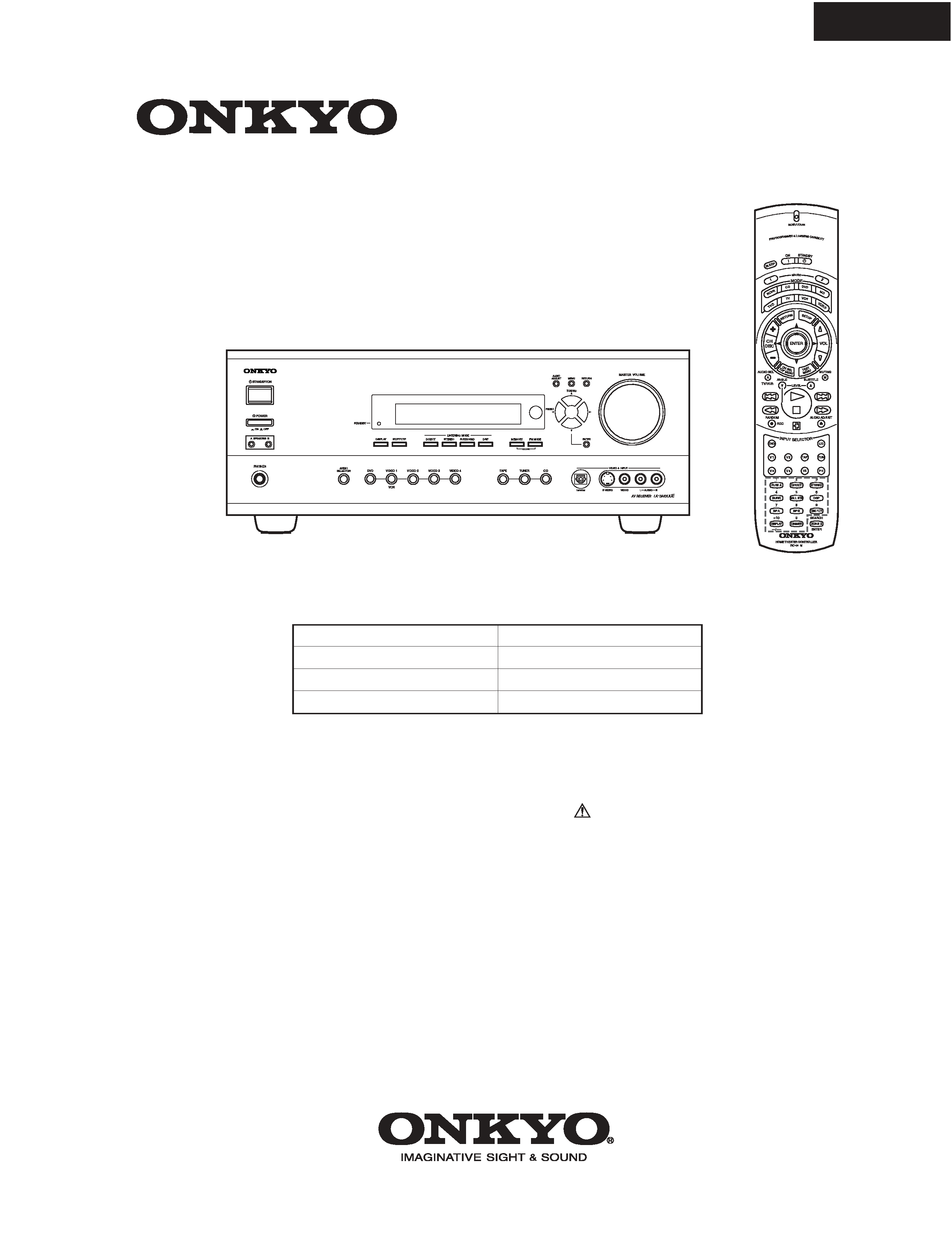
TX-SR600/E
SERVICE MANUAL
SERVICE MANUAL
AV RECEIVER
Black, Golden and Silver models
MODEL
TX-SR600/E
Ref. No. 3730
052002
RC-480M
SAFETY-RELATED COMPONENT
WARNING!!
COMPONENTS IDENTIFIED BY MARK
ON THE
SCHEMATIC DIAGRAM AND IN THE PARTS LIST ARE
CRITICAL FOR RISK OF FIRE AND ELECTRIC SHOCK.
REPLACE THESE COMPONENTS WITH ONKYO
PARTS WHOSE PART NUMBERS APPEAR AS SHOWN
IN THIS MANUAL.
MAKE LEAKAGE-CURRENT OR RESISTANCE
MEASUREMENTS TO DETERMINE THAT EXPOSED
PARTS ARE ACCEPTABLY INSULATED FROM THE
SUPPLY CIRCUIT BEFORE RETURNING THE
APPLIANCE TO THE CUSTOMER.

AMPLIFIER SECTION
Continuous average power output (FTC)
All channels:
80 W per channel min. RMS at 8 ohm,
2 channels driven from 20 Hz to 20
kHz with no more than 0.08% total
harmonic distortion.
105 W min. RMS at 6 ohm, 2 channels
driven from 1 kHz with no more
than 0.1% total harmonic distortion.
Continuous power output (DIN) 115 W at 6 ohm
Maximum power output (EIAJ)
145 W at 6 ohm
Dynamic power output (stereo)
2
215 W at 3 ohm
2
160 W at 4 ohm
2
95 W at 8 ohm
Total harmonic distortion:
0.08% at rated power
0.08% at 1 W output
IM distortion:
0.08% at rated power
0.08% at 1 W output
Damping factor:
60 at 8 ohm
Input sensitivity and impedance
LINE (CD, TAPE, DVD,
VIDEO 1-4):
200 mV, 47 kohm
MULTICHANNEL INPUT
(FRONT L/C/R, SURROUND
L/R):
200 mV, 47 kohm
(SUBWOOFER):
36 mV, 47 kohm
COAXIAL (DIGITAL):
0.5 Vp-p, 75 ohm
DVD, VIDEO 1, 2, 3, 4:
1 Vp-p, 75 ohm
1 Vp-p, 75 ohm (Y)
0.28 Vp-p, 75 ohm (C)
COMPONENT VIDEO 1, 2:
1 Vp-p, 75 ohm (Y)
0.7 Vp-p, 75 ohm (PB, PR)
Output level and impedance
Rec out (TAPE, VIDEO 1):
200 mV, 470 ohm
Pre out:
1 V, 470 ohm
VIDEO (VIDEO 1,
MONITOR OUT):
1 Vp-p, 75 ohm
1 Vp-p, 75 ohm (Y)
0.28 p-p, 75 ohm(C)
COMPONENT VIDEO OUT:
1 Vp-p, 75 ohm (Y)
0.7 Vp-p, 75 ohm (PB, PR)
Frequency response:
10 Hz to 100 kHz:+1/-3 dB
(CD in Direct mode)
Tone control
Bass:
±12 dB at 50 Hz
Treble:
±12 dB at 20,000 Hz
Signal-to-noise ratio (stereo)
CD/Tape:
100 dB (IHF A, 0.5 V input)
Muting:
- 50 dB
TUNER SECTION
FM
Tuning range:
87.5-108.0 MHz (50-kHz steps)
Usable sensitivity
Mono:
11.2 dBf, 1.0 µV (75 ohm IHF)
0.9 µV (75 ohm DIN)
Stereo:
17.2 dBf, 2.0 µV (75 ohm IHF)
23 µV (75 ohm DIN)
50 dB quieting sensitivity
Mono:
17.2 dBf, 2.0 µV (75 ohm )
Stereo:
37.2 dBf, 20 µV (75 ohm )
Capture ratio:
2.0 dB
Image rejection ratio
USA & Canadian models:
40 dB
Other area models:
85 dB
IF rejection ratio:
90 dB
Signal-to-noise ratio
Mono:
76 dB
Stereo:
70 dB
Alternate channel attenuation:
55 dB
Selectivity:
50 dB (DIN)
AM suppression ratio:
50 dB
Total harmonic distortion
Mono:
0.2%
Stereo:
0.3%
Frequency response:
30 Hz - 15 kHz, ±1.0 dB
Stereo separation:
45 dB at 1 kHz
30 dB at 100 Hz - 10 kHz
AM
Tuning range
USA & Canadian models:
530 to 1,710 kHz (10-kHz steps)
European & Australian models: 522 to 1,611 kHz (9-kHz steps)
Worldwide models:
531 to 1,602 kHz (9-kHz steps)
530 to 1,710 kHz (10-kHz steps)
Usable sensitivity:
30 µV
Image rejection ratio:
40 dB
IF rejection ratio:
40 dB
Signal-to-noise ratio:
40 dB
Total harmonic distortion:
0.7%
GENERAL
Power supply
USA & Canadian models:
AC 120 V, 60 Hz
European & Australian models: AC 230 - 240 V, 50 Hz
Some Asian models:
AC 220 - 230 V, 50/60 Hz
Worldwide models:
AC 220 - 230 and 120 V switchable,
50/60 Hz
Power consumption
USA & Canadian models:
5.5 A
Other models:
450 W
Dimensions (W H
D):
435
175 431.5 mm
17-1/8"
6-7/8"
16-15/16"
Weight
USA & Canadian models:
24.5 lbs.
Other models:
12.1 kg
REMOTE CONTROLLER
Transmitter:
Infrared
Signal range:
Approx. 16 ft., 5 meters
Power supply:
Two "AA" batteries (1.5 V
2)
Specifications and features are subject to change without notice.
RIAA deviation:
20 Hz to 20 kHz:±0.8 dB
TX-SR600/E
SPECIFICATIONS
L
27122965
REMOTE
CONTROL
CAUTION: SPEAKER IMPEDANCE
6 OHMS MIN. /SPEAKER
ANTENNA
FM
75
AM
COAXIAL
OPTICAL
1
2
IN
IN
IN
IN
FRONT
SURR
CENTER
SUB
WOOFER
VIDEO 2
VIDEO 1
OUT
DIGITAL INPUT
DVD
MONITOR
OUT
DVD
TAPE
CD
SUBWOOFER
PRE OUT
L
R
FRONT
SPEAKERS
SURROUND
SPEAKERS
CENTER
SPEAKER
R
L
R
L
R
VIDEO 3
VIDEO 2
VIDEO 3
VIDEO 1
VIDEO
OPTICAL
IN
IN
IN
IN
DIGITAL
OUTPUT
IN
INPUT 1
INPUT 2
OUTPUT
COMPONENT VIDEO
PR
PB
Y
OUT
OUT
A
B
SURROUND BACK
SPEAKER
DIGITAL
INPUT
L
R
R
L
S VIDEO
AC OUTLETS
AV RECEIVER
MODEL NO.
TX-SR600E
SWITCHED
TOTAL 100W MAX.
AC 230-240V
50 Hz
4. Memory Preservation
This unit does not require memory preserv ation batteries. A
built-in memory power back-up system preserves the contents
of the memory during po wer f ailures and e ven when the unit is
unplugged. The unit must be plugged in order to char ge the
back-up system.
The memory preserv ation period after the unit has been
unplugged v aries depending on climate and placement of the
unit. On the average, memory contents are protected over a
period of a fe w weeks after the last time the unit has been
unplugged. This period is shorter when the unit is e xposed to a
highly humid climate.
2. To initialize the unit
This device employs a microprocessor to perform various
functions and operations. If interference generated by an external
power supply, radio wave, or other electrical source results in
accident which causes the specified operations and functions to
operate abnormally.
To perform a result, please follow the procedure below.
1.Press and hold down the VIDEO-1 button, then press the
STANDBY/ON button.
2.After "clear" is displayed, the preset memory and each
mode stored in the memory, such as surround, are
initialized and will return to the factory setting.
3. Safety-check out
(Only U.S.A. model)
After correcting the original service problem, perform the
following safety check before releasing the set to the customer.
Connect the insulating-resistance tester between the plug of power
supply cord and screw on the back panel.
Specifications: 3.3Mohm+/-10% at 500V.
1. Replacing the fuses
This symbol located near the fuses indicates that the
fuse used is fast operating type. For continued protection against
fire hazard, replace with same type fuse. For fuse rating refer to
the marking adjacent to the symbol.
Ce symbole indique que le fusible utlise est a rapide.
Pour une protection permanente, n'untiliser que fusibles de
meme type. Ce darnier est la qu le present symbol est
appse.
CIRCUIT NO. PART NO.
DESCRIPTION
Note: <D>:120V model only
<O>: Other models except 120V model
<T>: Asian model only for 230V
<R>: Chinese model only
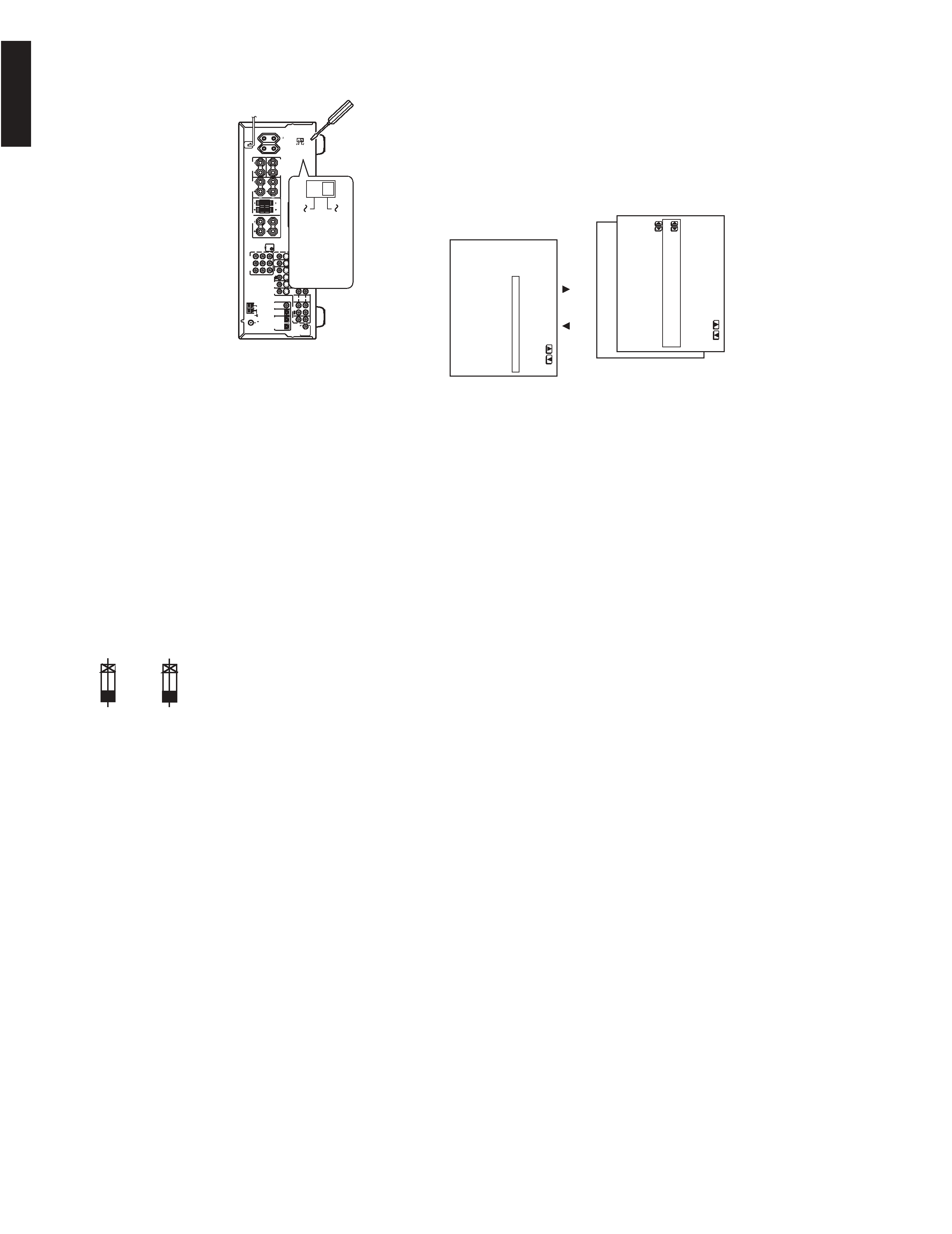
5.Setting the voltage selector (Worldwide models
only)
Worldwide models are equipped with a voltage selector to conform
with local power supplies. Be sure to set this switch to match the
voltage of the power supply in your area before plugging in the unit.
Determine the proper voltage for your area: 220-230 V or 120 V. If
the preset voltage is not correct for your area, insert a screwdriver
into the groove in the switch. Slide the switch all the way to the
upper (120 V) or to the lower (220-230 V), whichever is appropriate.
6.Setting the AM tuning step frequency
(Worldwide models only)
F6901,F6902
F901
F902
F903
F9501
ONT
SURR
CENTER
SUB
WOOFER
VIDEO 1
DVD
L
R
SURROUND
BACK
R
L
PRE OUT
OUT
S
IR
IN
AV RECEIVER
MODEL NO.
TX-SR700E
120V
220-230V
120V
VOLTAGE
SELECTOR
220-230V
1. Press the MENU button on the front panel or SETUP
button on the remote controller.
The main menu appears.
* Menu *****************
1.Speaker Config
2.Speaker Distance
3.Level Calibration
4.Input Setup
5.OSD Setup
6.Preference
|ENTER|Quit:|SETUP|
2. Use the
and
cursor buttons to select " 6.
Preference
" and then press the ENTER button.
* Menu *****************
1.Speaker Config
2.Speaker Distance
3.Level Calibration
4.Input Setup
5.OSD Setup
6.Preference
6.Preference
***********************
a.Headphones Level
: 0dB
b.AM Frequency Step
:9 kHz
Quit:|SETUP|
b. AM Frequency Step
This setting only appears on the worldwide model. It determines the
increment amount or decrement amount when adjusting the AM
tuner frequency. The initial setting is 9 kHz, and this needs only to be
changed if you are using the unit in a 10-kHz region.
252199
10A-UL,Fuse <D>
252100
10A-EAK,Fuse <O>
F901
252261
8A-T/UL-ST2,Fuse <D/T/Q/R>
252198 or
8A-UL or
252077,
4A-SE-EAK,
252243 or
4A-SE-TL250V or
252277
4A-SE-TL250V,Fuse <O>
252075,
2.5A-SE-EAK,
252241 or
2.5A-SE-TL250V or
252275
2.5A-SE-TL250V,Fuse <O>
252160 or
2.5A-UL/T-237 or
252254
2.5A-T/UL-ST2,Fuse <D>
252075,
2.5A-SE-EAK,
252241 or
2.5A-SE-TL250V or
252275
2.5A-SE-TL250V,Fuse <O>
TX-SR600/E
SERVICE PROCEDURES
1
2
4
5
6
7
8
9
10
11
14
16
21
22
23
24
25
26
31
32
33
34
41
51
52
F6901
F901
F902
F9501
P101
P6931
P7501
P7502
P901
Q6050
Q6065
Q6055
Q6060
T901
U1
U2
U3
U4
U5
U6
U11
U12
U8
U14
U16
U17
U19
U20
U21
U27
U28
U24
U26
U29
U31
U32
U36
42
42
9
42
4
4
4
14
6
12
46
47
4
24
F6902
U23
27
36
36
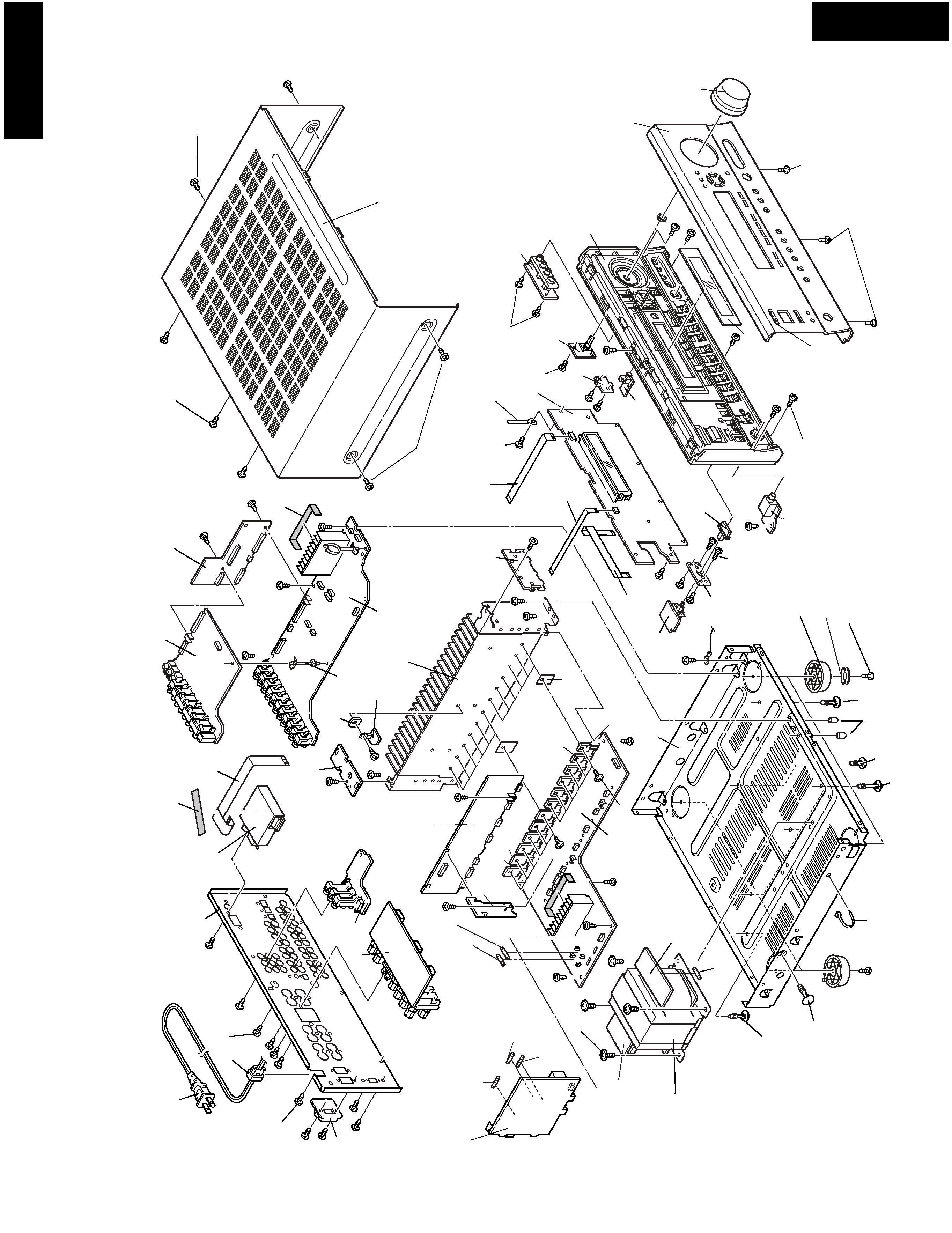
TX-SR600/E
EXPLODED VIEW
TX-SR600/E
F903
REF.NO. PART NO.
DESCRIPTIONS
1
27111271B
Front bracket <B>
27111273B
Front bracket <G>
27111272B
Front bracket <S>
2
27212382
Front panel <D>
27212383
Front panel <B> <T/A>
27212384
Front panel <B> <P>
27212385
Front panel <S>
27212386
Front panel <G>
4
838130088
3TTB+8B,Self-tapping screw
5
28135244
Badge <B>
28135245
Badge <G/S>
6
838430088
3TTB+8B(BC),Self-tapping screw
7
28325907
Knob, volume <D>
28326010
Knob, volume <B> <O>
28326011
Knob, volume <S>
28326012
Knob, volume <G>
8
27122964A
Rear panel <D>
27122965A
Rear panel <P>
27122966A
Rear panel <T>
27122967A
Rear panel <A>
27122968A
Rear panel <R/Q>
27122970A
Rear panel <K>
9
838430088
3TTB+8B(BC),Self-tapping screw
10
82143010
3P+10FN(BC),Pan head screw
11
27191130
Holder, outlet <R>
12
28325497A
Knob, power <B> <O>
28325499A
Knob, power <G>
28325547A
Knob, power <S>
14
27255004
CS-1U,Clip
16
28191957
Clear plate <B>
28191958
Clear plate <G/S>
21
27100418A
Chassis
22
27190693A
KGLS-6RF,Holder
23
27190428A
KGLS-10RF,Holder
24
27190266
KGLS-12RF,Holder
25
27190657
KGLS-18RF,Holder
26
27190369
Holder
27
27300750
Bushing, cord
31
27160504
Heat sink
32
801433
3SMS8W.SW+14B(BC),Self-tapping screw
33
830440089
4TTC+8C(BC),Self-tapping screw
34
28330135A
Cap
36
29110083
Tape,cloth
41
28184835
Top cover <B>
28184837
Top cover <G>
28184836
Top cover <S>
42
838430088
3TTB+8B(BC),Self-tapping screw <B>
838930088
3TTB+8B(UN),Self-tapping screw <G/S>
46
27175319B
Leg
47
28141494
Cushion
51
260208
Binder
52
223024
AC238,Isolated sheet
F6901,
252199
10A-UL,Fuse <D>
F6902
252100
10A-EAK,Fuse <O>
REF.NO. PART NO.
DESCRIPTIONS
F901
252261
8A-T/UL-ST2,Fuse <D/T/Q/R>
252198 or
8A-UL or
F902
252077,
4A-SE-EAK,
252243 or
4A-SE-TL250V or
252277
4A-SE-TL250V,Fuse <O>
F903
252075,
2.5A-SE-EAK,
252241 or
2.5A-SE-TL250V or
252275
2.5A-SE-TL250V,Fuse <O>
F9501
252160 or
2.5A-UL/T-237 or
252254
2.5A-T/UL-ST2,Fuse <D>
252075,
2.5A-SE-EAK,
252241 or
2.5A-SE-TL250V or
252275
2.5A-SE-TL250V,Fuse <O>
P101
2047152522
NCFC7-152522,Flexible cable
P6931
2047134512
NCFC7-134512,Flexible cable
P7501
2047113022
NCFC7-113022,Flexible cable
P7502
2047061522
NCFC7-061522,Flexible cable
P901
253332HIT or
AS-UC-2 or
253333VOL
AS-UC-2,Power supply cord <D>
253197HIT or
AS-SAA or
253307VOL
AS-SAA,Power supply cord <A>
253233KAW
AS-CEE-2,Power supply cord <P/T/K>
253198HIT
AS-BS,Power supply cord <Q>
253337HIT or
AS-CCEE or
253338VOL
AS-CCEE,Power supply cord <R>
P902A
25052665
NSCT-2P2561,AC outlet <K>
Q6050~
2202843 or
2SC5242-O or
Q6052
2202842
2SC5242-R,Transistor
Q6053~
2203663,
MN130S-O,
Q6055
2202842,
2SC5242-R,
2202843,
2SC5242-O,
2203664 or
MN130S-Y or
2203666
MN130S-P,Transistor
Q6060~
2202833 or
2SA1962-O or
Q6062
2202832
2SA1962-R,Transistor
Q6063~
2203673,
MP130S-O,
Q6065
2202832,
2SA1962-R,
2202833,
2SA1962-O,
2203674 or
MP130S-Y or
2203676
MP130S-P,Transistor
T901
2301584
NPT-1438D,Power transformer <D>
2301585
NPT-1438P,Power transformer <P/A>
2301586
NPT-1438DG,Power transformer <T/K/Q/R>
!
!
!
!
!
!
*
*
*
*
*
*
*
*
*
*
*
*
*
*
!
!
!
!
!
!
!
!
!
!
!
!
!
!
!
!
!
!
!
!
<B>:Black model only
<S>:Silver model only
<G>:Golden model only
<D>:120V model only
<O>:Other models except 120V model
<P>:European model only
<T>:Asian model only
<A>:Australian model only
<R>:Chinese model only
<Q>:Hongkong model only
<K>:korean model only
NOTE:
CAUTION: Replacement for transistor of mark *, if necessary
must be made from the same beta group (HFE) as
the original type.
NOTE: THE COMPONENTS IDENTIFIED BY MARK !
ARE CRITICAL FOR RISK OF FIRE AND
ELECTRIC SHOCK. REPLACE ONLY WITH
PART NUMBER SPECIFIED.
TX-SR600/E
EXPLODED VIEW
PARTS LIST