AMPLIFIER SECTION
Power Output (FTC)
All channels 22 watts per channel min.
RMS. into 6 ohms two channel driven,
1,000 Hz with no more than 0.6 % total
harmonic distortion.
Continuous power output (DIN)
All channels 22 watts per channel min.
RMS. into 6 ohms two channel driven,
1,000 Hz
Maximun power output (EIAJ)
5 x 28 watts at 6 ohms
Dynamic power output
2 x 26 watts at 6 ohms
2 x 22 watts at 8 ohms
Total Harmonic Distortion 0.6 % at rated power
IM Distortion
0.6 % at rated power
Damping Factor
40 at 8 ohms
Input Sensitivity and Impedance
DIGITAL INPUT DVD, HD (OPTICAL) 0.5 Vp-p, 75 ohms
DIGITAL INPUT VIDEO 2 (COAXIAL)
0.5 Vp-p, 75 ohms
LINE (DVD/CD, VIDEO 1, 2, HD, TAPE/MD) 150 mV/50 kohms
Composite (DVD/CD, VIDEO 1, 2)
1 Vp-p, 75 ohms
S-VIDEO (DVD/CD, VIDEO 1, 2)
Y: 1 Vp-p, 75 ohms
C: 0.28 Vp-p, 75 ohms
TUNER SECTION
Tuning Range
FM: 87.50 to 108.00 MHz (50 kHz steps)
AM: (USA and Canadian models)
530 to 1710 kHz (10 kHz steps)
Usable Sensitivity
FM: Mono
11.2 dBf, 1.0 µV (75 ohms IHF)
0.9 µV (75 ohms DIN)
Stereo
17.2 dBf, 2.0 µV (75 ohms IHF)
23 µV (75 ohms DIN)
AM: 30 µV
50 dB Quieting Sensitivity
FM: Mono
17.2 dBf, 2.0 µV (75 ohms)
Stereo
37.2 dBf, 20.0 µV (75 ohms)
Capture Ratio
FM: 2.0 dB
Image Rejection Ratio
FM: (USA and Canadian models)
40 dB
AM: 40 dB
IF Rejection Ratio
FM: 90 dB
AM: 40 dB
Signal-to-noise Ratio
FM: Mono
76 dB, IHF
Stereo
70 dB, IHF
AM: 40 dB
Alternate Channel Att. (+/ 400 kHz) FM: Mono
55 dB, IHF
Selectivity
FM: 50 dB, DIN
AM Suppression Ratio
FM: 50 dB
Harmonic Distortion
FM: Mono
0.2 %
Stereo
0.3 %
AM:
0.7 %
Frequency response
FM: 30 to 15,000 Hz (+/ 1.0 dB)
Stereo Separation
FM: 45 dB at 1,000 Hz
30 dB at 100 to 10,000 Hz
Stereo Threshold
FM: 17.2 dBf, 20 µV (75 ohms)
GENERAL
Power Supply Rating
(USA and Canadian models)
and Power Consumption AC 120 V, 60Hz
120W
(Some Asian models)
AC 220-230 V, 50/60Hz 105W
(Other models)
AC 230-240 V, 50Hz 105W
Specifications and features are subject to change without notice.
Output Level and Impedance
REC OUT (VIDEO 1, TAPE/MD, HD)
150 mV, 2.2 kohms
SUB WOOFER PRE OUT
1 V, 2.2 kohms
Composite (MON OUT, VIDEO 1)
1 Vp-p, 75 ohms
S-VIDEO (MON OUT, VIDEO 1)
Y: 1 Vp-p, 75 ohms
C: 0.28 Vp-p, 75 ohms
Frequency Response
10 to 70,000 Hz : +/ 1.5 dB
Acoustic Control
1: +6 dB at 40 Hz
2: +10 dB at 40 Hz
+7 dB at 10,000 Hz
Signal-to-noise Ratio
100 dB (IHF)
Muting
dB
(Other models)
522 to 1611 kHz (9 kHz steps)
(Other models)
85 dB
Dimensions (W x H x D) 435 x 81 x 377 mm (17-1/8 x 3-3/16 x 14-13/16 ins.)
Weight
6.1 kg (13.4 lb.)
8
TX-L5
SPECIFICATIONS
SUBWOOFER MODE
SURROUND
STEREO
ON
STANDBY
POWER
STANDBY/ ON
ON
OFF
PHONES
ACOUSTIC
CONTROL
TUNING/PRESET
DVD/CD
VIDEO
1
VIDEO
2
H D
MD/TAPE
FM
AM
INPUT
VOLUME
AV RECEIVER
TX-L
5
MEMORY
FM MODE
RDS
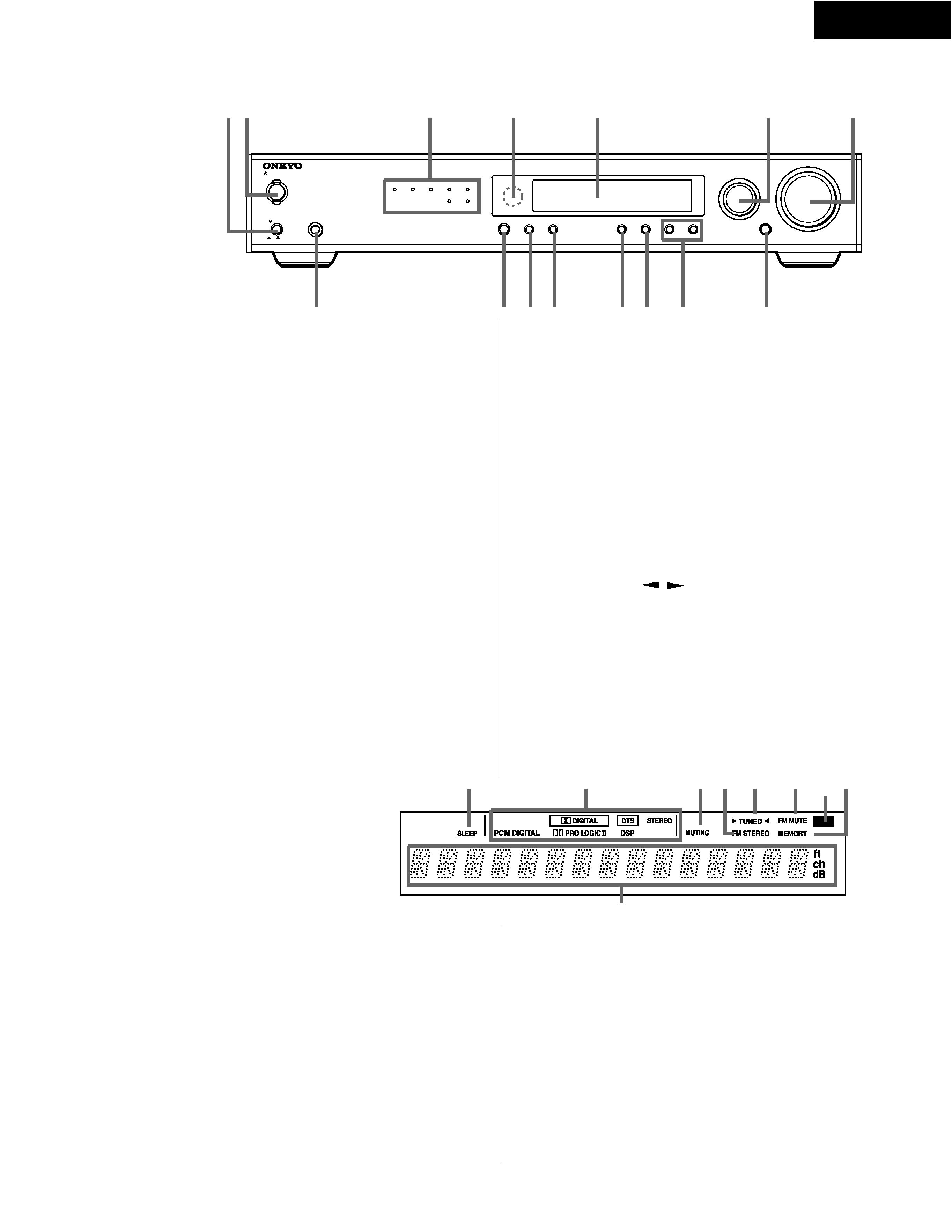
SLEEP indicator
Lights up when the sleep timer is active.
Source/Listening mode indicators
One of these indicators lights to show the format of the current
source as "PCM DIGITAL", " DIGITAL" or "DTS". In addition, one
of the listening mode indicators "PRO LOGIC II", "DSP" and
"STEREO" lights according to the current listening mode.
MUTING indicator
Flashes when the mute function is active.
FM STEREO indicator
Lights up when an FM stereo broadcast station is received.
TUNED indicator
Lights up when a radio station is received.
FM MUTE indicator
Lights up to indicate FM muting. It extinguishes when the monaural
reception mode is started by pressing the FM MODE button.
RDS indicator (European models only)
Lights up when a RDS station is received.
MEMORY indicator
Lights up when the MEMORY button is pressed in the radio station
preset operation.
Multi function display
In usual operation, shows the current input source and volume.
When the FM or AM input is selected, it shows the frequency and
preset number. When the DISPLAY button is pressed, it shows the
listening mode and input source format. However, it does not show
the source format when the input source signal is analog, or when
the FM or AM source is selected.
POWER switch
Turns on the main power supply for the TX-L5. The
TX-L5 enters standby state and the STANDBY indicator lights up.
Pressing the switch again to the off position ( OFF) shuts down the
main power supply into the TX-L5.
STANDBY/ON button, ON indicator, STANDBY indicator
When STANDBY/ON button is pressed to ON while the POWER
switch is set to ON, the display will light to show the current volume
setting for about 5 seconds then show the current sound input
source and listening mode. Pressing the button again returns the
TX-L5 to the standby state. This state turns off the display, disables
control functions.
Source indicators
One of these indicators lights to show the current source.
Remote control sensor
This sensor receives the control signals from the remote controller.
Display
INPUT dial
The INPUT dial is used to select the input source.
VOLUME dial
The VOLUME dial is used to control the volume level. Turn the dial
clockwise to increase the volume level and counterclockwise to
decrease it.
PHONES jack
This is a standard stereo jack for connecting stereo headphones.
The audio for the front right and left speakers are sent to the
headphone speakers. When the headphones are plugged in, the
listening mode automatically changes to STEREO and sounds are
not output from the speakers.
SURROUND button
Press this button to select a surround mode for current input source.
STEREO button
Press this button to change the sound to stereo.
SUBWOOFER MODE button
Press to select the subwoofer mode.
MEMORY button
This button is used to assign the radio station that is currently tuned
in to a preset channel or delete a previously preset station.
FM MODE button
Press to switch the reception mode between stereo and monaural. If
audio is interrupted or noise interferes with audio during FM stereo
broadcasting, press this button to switch to the monaural reception
mode.
TUNING/PRESET
/
button
Use these buttons to change the tuner frequency. The tuner
frequency is displayed in the front display and it can be changed in
50 kHz increments for FM and 10 kHz (or 9 kHz) increments for AM.
Also, These buttons make it possible to store desired radio stations
under the desired preset numbers and recall them with an easy
operation.
ACOUSTIC CONTROL button/indicator
Press to change the acoustic mode to enjoy more dynamic sounds
by boosting the super bass/high frequency sounds.
1 2
3
4
5
6
7
8
9
10 11
12 13
14
15
1
2
3
4
5
6
7
8
9
10
11
12
13
14
15
1
2
3
4
5
6
7 8
9
1
2
3
4
5
6
7
8
9
TX-L5
PANEL VIEWS
Front Panel
R
L
FRONT SPEAKERS
SURROUND
SPEAKERS
CENTER
SPEAKER
R
L
ANTENNA
AM
FM 75
REMOTE
CONTROL
S VIDEO
SUB
WOOFER
PRE OUT
MON OUT
VIDEO
IN
IN
OUT IN
IN
OUT
IN
IN
DVD/CD
MON
OUT
DVD/CD
L
R
IN
AUDIO
VIDEO 1
VIDEO 2
MD/TAPE
OUT
IN
OUT
IN
OUT
IN
IN
HD
DVD/CD
L
R
VIDEO 1
VIDEO 2
VIDEO 2
VIDEO 1
DIGITAL INPUT
(OPTICAL)
(COAXIAL)
VIDEO 2
DVD
HD
(OPTICAL)
AV RECEIVER
MODEL NO.
TX-L5
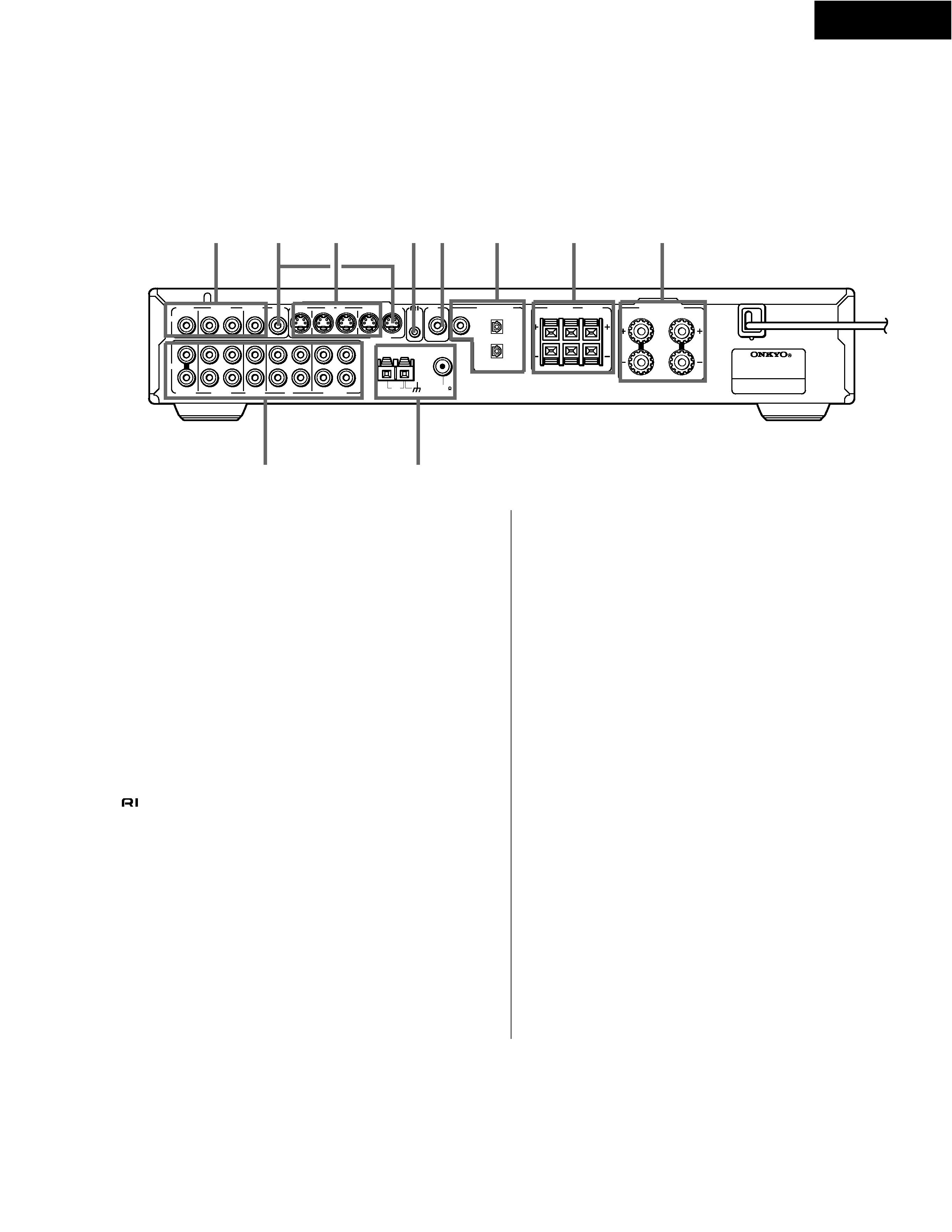
1.VIDEO (DVD/CD IN / VIDEO 1 OUT/IN / VIDEO 2 IN)
There are 3 video inputs and 1 output. Connect DVD players, LD
players, VCRs or other video components to the video inputs. The
video output channel can be used to be connected to video tape
recorder for making recordings.
2.MON OUT
The monitor output includes both RCA type and S video
configurations. This output is for connecting television monitors or
projectors.
3.S VIDEO (DVD/CD IN / VIDEO 1 OUT/IN / VIDEO 2 IN)
There are 3 video inputs and 1 output. Connect DVD players, LD
players, VCRs or other video components to the video inputs. The
video output channel can be used to be connected to video tape
recorder for making recordings.
(REMOTE CONTROL)
Connect the Onkyo components that have connectors such as a
CD player, and cassette tape deck using the cables provided
with them. When these components are interconnected, they can be
controlled from the remote controller provided with the TX-L5.
After connecting the connectors, check the operation of the
remote controller buttons for use in controlling other components.
· The connectors are only effective if they are used in
conjunction with an Onkyo amplifier with an connector. Do not
connect to a component other than Onkyo component with an
connector. Doing so may damage the TX-L5.
· Connecting cable only does not make the system operational.
You must also connect the audio cables as well.
· If the connected component has two connectors, you can use
either one to connect to the TX-L5. The other one can be used to
daisy chain with another component.
SUB WOOFER PRE OUT
This terminal is for connecting an active subwoofer.
DIGITAL INPUT (DVD, HD (OPTICAL), VIDEO 2 (COAXIAL))
These are the digital audio inputs. There are 2 digital inputs with
optical jacks and 1 with a coaxial jack. The inputs accept digital
audio signals from DVD players, hard disk recorders, CD players, or
other digital source component.
SURROUND SPEAKERS L/R, CENTER SPEAKER
Speaker terminals are provided for the center, surround left and
surround right speakers.
8. FRONT SPEAKERS L/R
Speaker terminals are provided for the front left, front right speakers.
Speaker outputs are compatible with banana plug connectors (other
than European models).
9. AUDIO L/R (DVD/CD IN / VIDEO 1 OUT/IN / VIDEO 2 IN /
HD OUT/IN / MD/TAPE OUT/IN)
These are the analog audio inputs and outputs. There are 5 audio
inputs and 3 audio outputs. The audio inputs and outputs require
RCA type connectors.
When connecting a VCR or other video component, make sure you
connect the audio and video leads together (i.e., both to VIDEO 1).
10. ANTENNA
These terminals are for connecting the FM antenna and AM
antenna.
4.
5.
6.
7.
1
2
3
4
5
6
7
8
9
10
TX-L5
PANEL VIEWS
Rear Panel