BMDD
BMPP,SMPP
BMPA,GMPA
BMWT,GMWT
GMWR
120V AC, 60Hz
230-240V AC, 50Hz
220-230V/120V AC,
50/60 Hz
Black, Golden and Silver models
Ref. No. 3678
042001
SERVICE MANUAL
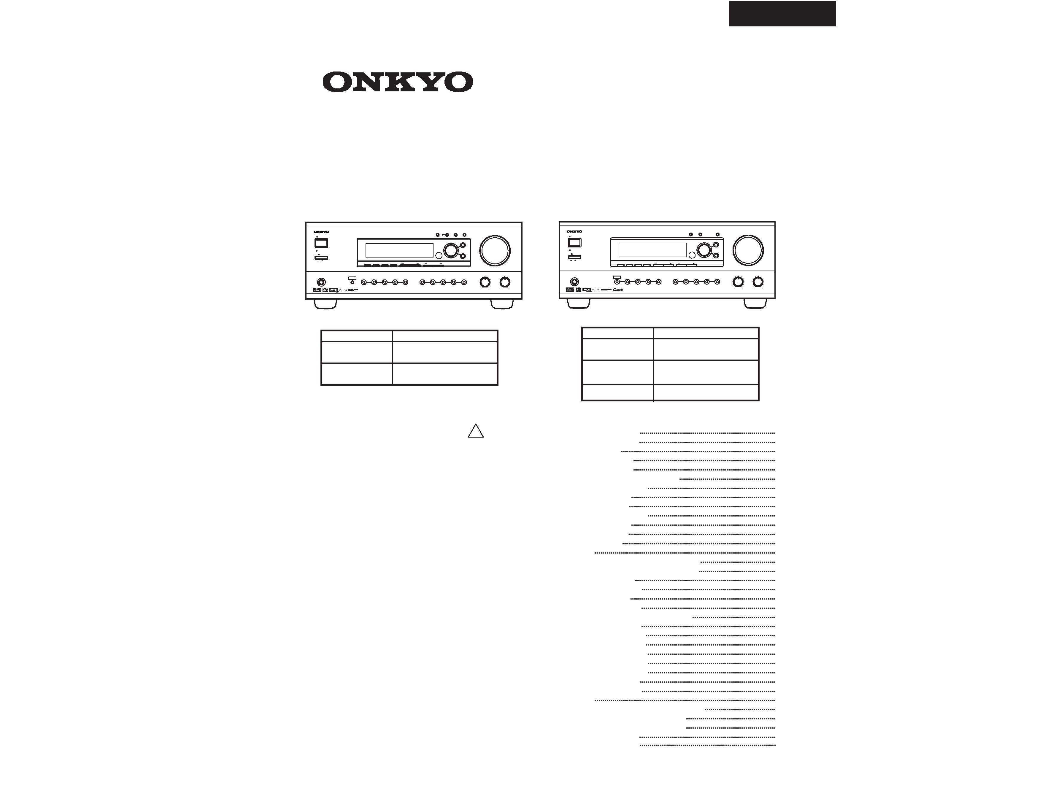
AUDIO VIDEO
CONTROL RECEIVER
MODEL TX-DS696
TABLE OF CONTENTS
2
3
4
5
8
11
20
20
22
24
24
26
27
28
29
34
39
41
43
45
47
47
51
55
59
63
67
71
75
81
87
89
93
97
98
SAFETY-RELATED COMPONENT WARNING!!
COMPONENTS IDENTIFIED BY MARK
ON THE
CRITICAL FOR RISK OF FIRE AND ELECTRIC SHOCK.
REPLACE THESE COMPONENTS WITH ONKYO
PARTS WHOSE PART NUMBER APPEAR AS SHOWN
IN THIS MANUAL.
MAKE LEAKAGE CURRENT OR RESISTANCE
MEASUREMENTS TO DETERMINE THAT EXPOSED
PARTS ARE ACCEPTABLY INSULATED FROM THE
SUPPLY CIRCUIT BEFORE RETURNING THE
APPLIANCE TO THE CUSTOMER.
SCHEMATIC DIAGRAM AND IN THE PARTS LIST ARE
AUDIO VIDEO
CONTROL RECEIVER
MODEL TX-DS595
BMDD
BMPP,SMPP
BMPA,GMPA
BMWT,GMWT
GMWR
120V AC, 60Hz
230-240V AC, 50Hz
220-230V/120V AC,
50/60 Hz
Black, Golden and Silver models
GMGT
220-230V AC,50 Hz
Specifications TX-DS595
Specifications TX-DS696
Service procedures
Panel views TX-DS595
Panel views TX-DS696
IC block diagrams and descriptions
Microprocessor TX-DS595
Main microprocessor
Sub microprocessor
Microprocessor TX-DS696
Main microprocessor
Sub microprocessor
About debug mode
FL tube view
Printed circuit board-parts list TX-DS595
Printed cirucit board-parts list TX-DS696
Wiring view TX-DS595
Block diagram TX-DS595
Wirng view TX-DS696
Block diagram TX-DS696
Schematic diagrams & PC board views
Input section TX-DS595
Input section TX-DS696
Power amplifier section 1
Power amplifier section 2
Display section TX-DS595
Display section TX-DS696
Video section TX-DS595
Video section TX-DS696
DSP section
Adjustments and confirmation procedures
Exploded view & Parts list TX-DS595
Exploded view & Parts list TX-DS696
Packing view TX-DS595
Packing view TX-DS696
STANDBY/ON
STANDBY
OFF
ON
POWER
MASTER VOLUME
BASS
TREBLE
AV RECEIVER
TX-DS
696
PHONES
FM
AM
PHONO
C D
TAPE
DVD
REC OUT
ZONE
2
ZONE
2 LEVEL
CH LEVEL
VIDEO
3
VIDEO
4
VIDEO
2
VIDEO
1
VCR
2
VCR
1
AUDIO
SELECTOR
TUNING
PRESET
SMART SCAN NAVIGATOR
PRESET MEMORY
FM MODE
DISPLAY
DIMMER
PUSH TO ENTER
DSP/MODE ADJ
SETUP
RETURN
STANDBY/ON
STANDBY
OFF
ON
POWER
MASTER VOLUME
BASS
TREBLE
AV RECEIVER
TX-DS
595
PHONES
FM
AM
PHONO
C D
TAPE
CH LEVEL
VIDEO
2
VIDEO
3
VIDEO
1
DVD
VCR
TUNING
PRESET
SMART SCAN NAVIGATOR
PRESET MEMORY
FM MODE
DISPLAY
RT/PTY/TP
PUSH TO ENTER
DSP/MODE ADJ
SETUP
RETURN
AB
SPEAKERS
AUDIO
SELECTOR
!
TX-DS595/696

AMPLIFIER SECTION
Continuous Average Power output (FTC)
All channels:
75 W per channel min. RMS at 8
ohm , 2 channels driven from 20Hz
to 20 kHz with no more than
0.08% total harmonic distortion.
100 W min. RMS at 6 ohm, 2
channels driven from 1 kHz with
no more than 0.1% total
harmonic distortion.
Continuous Power output (DIN)
110 W at 6 ohm
Maximum Power output (EIAJ)
140 W at 6 ohm
Dynamic Power Output (Stereo) 2
210 W at 3
2
155 W at 4
2
90 W at 8
Total Harmonic Distortion:
0.08% at rated power
0.08% at 1 W output
IM Distortion:
0.08% at rated power
0.08% at 1 W output
Damping Factor:
60 at 8
Input Sensitivity and Impedance
PHONO:
2.5 mV, 50 k
LINE (CD, TAPE, DVD,
VIDEO 1,2,3):
200 mV, 50 k
MULTICHANNEL INPUT
(FRONT L/C/R, SURROUND L/R):
200 mV, 50 k
(SUBWOOFER):
36 mV, 50 k
COAXIAL 1, 2 (DIGITAL):
0.5 Vp-p, 75
DVD, VIDEO1,2,3:
1 Vp-p, 75
1 Vp-p, 75
(Y)
0.28 Vp-p, 75
(C)
Output Level and Impedance
Rec out (TAPE, VIDEO 1):
200 mV, 2.2 k
Pre out:
1 V, 470 ohm
VIDEO (VIDEO 1, MONITOR OUT):
1 Vp-p, 75 ohm
1 Vp-p, 75 ohm (Y)
0.28 Vp-p, 75
(C)
Phono Overload:
180 mV RMS at 1 kHz, 0.5% T.H.D.
Frequency Response:
10 Hz to 100 kHz: +1 dB, - 3 dB
RIAA Deviation:
20 Hz to 20 kHz : ±0.8 dB
Tone Control
Bass:
±10 dB at 50 Hz
Treble:
±10 dB at 20 kHz
Signal-to-Noise Ratio (Stereo)
Phono:
80 dB (IHF A, 5 mV input)
CD/Tape:
100 dB (IHF A, 0.5 V input)
Muting:
50 dB
TUNER SECTION
FM
Tuning Range:
87.5 to 108.0 MHz (50-kHz steps)
Usable Sensitivity
Mono:
11.2 dBf, 1.0 µV (75 ohm IHF)
0.9 µV (75 ohm DIN)
Stereo:
17.2 dBf, 2.0 µV (75 ohm IHF)
23 µV (75 ohm DIN)
50 dB Quieting Sensitivity
Mono:
17.2 dBf, 2.0 µV (75 ohm)
Stereo:
37.2 dBf, 20 µV (75 ohm)
Capture Ratio:
2.0 dB
Image Rejection Ratio:
USA & Canadian models:
40 dB
Other area models:
85 dB
IF Rejection Ratio:
90 dB
Signal-to-Noise Ratio
Mono:
76 dB
Stereo:
70 dB
Alternate Channel Attenuation:
55 dB
Selectivity:
50 dB (DIN)
AM Suppression Ratio:
50 dB
Total Harmonic Distortion
Mono:
0.2%
Stereo:
0.3%
Frequency Response:
30 Hz to 15 kHz, ±1.0 dB
Stereo Separation:
45 dB at 1 kHz
30 dB at 100 Hz to 10 kHz
AM
Tuning Range
USA & Canadian models:
530 to 1,710 kHz (10-kHz steps)
European & Australian models:
522 to 1,611 kHz (9-kHz steps)
Worldwide models:
531 to 1,602 kHz (9-kHz steps)
530 to 1,710 kHz (10-kHz steps)
Usable Sensitivity:
30 µV
Image Rejection Ratio:
40 dB
IF Rejection Ratio:
40 dB
Signal-to-Noise Ratio:
40 dB
Total Harmonic Distortion:
0.7%
GENERAL
Power Supply:
AC 120 V, 60 Hz
(USA & Canadian models)
AC 230-240 V, 50 Hz
(European & Australian models)
AC 220-230 and 120 V switchable,
50/60 Hz (Worldwide models)
Power Consumption:
4.7 A
380 W
Dimensions (W
H
D):
435
175
431 mm
17-1/8"
6-7/8"
16-15/16"
Weight:
25.4 lbs. (USA & Canadian models)
12.5 kg (Other models)
REMOTE CONTROLLER
Transmitter:
Infrared
Signal range:
Approx. 5 meters, 16 ft.
Power supply:
Two " AA " batteries (1.5 V 2)
Specifications and features are subject to change without notice.
Power supply and voltage vary depending on the area in which the
unit is purchased.
ohm
ohm
ohm
ohm
ohm
ohm
ohm
ohm
ohm
ohm
ohm
ohm
ohm
ohm
TX-DS595
SPECIFICATIONS

AMPLIFIER SECTION
Continuous Average Power output (FTC)
All channels:
100 W per channel min. RMS at 8
ohm , 2 channels driven from 20Hz
to 20 kHz with no more than
0.08% total harmonic distortion.
125 W min. RMS at 6 ohm, 2
channels driven from 1 kHz with
no more than 0.1% total
harmonic distortion.
Continuous Power output (DIN)
130 W at 6 ohm
Maximum Power output (EIAJ)
160 W at 6 ohm
Dynamic Power Output (Stereo) 2
230 W at 3
2
170 W at 4
2
115 W at 8
Total Harmonic Distortion:
0.08% at rated power
0.08% at 1 W output
IM Distortion:
0.08% at rated power
0.08% at 1 W output
Damping Factor:
60 at 8
Input Sensitivity and Impedance
PHONO:
2.5 mV, 50 k
LINE (CD, TAPE, DVD,
VIDEO 1-4):
200 mV, 50 k
MULTICHANNEL INPUT
(FRONT L/C/R, SURROUND L/R):
200 mV, 50 k
(SUBWOOFER):
36 mV, 50 k
COAXIAL 1, 2 (DIGITAL):
0.5 Vp-p, 75
DVD, VIDEO1-4:
1 Vp-p, 75
1 Vp-p, 75
(Y)
0.28 Vp-p, 75
(C)
COMPONENT VIDEO 1, 2:
1 Vp-p, 75
(Y)
0.7 Vp-p, 75
(CB /CR, PB /PR )
Output Level and Impedance
Rec out (TAPE, VIDEO 1, 2):
200 mV, 2.2 k
Pre out:
1 V, 470 ohm
VIDEO (VIDEO 1, 2, MONITOR OUT):
1 Vp-p, 75 ohm
1 Vp-p, 75 ohm (Y)
0.28 Vp-p, 75
(C)
COMPONENT VIDEO OUT:
1 Vp-p, 75 ohm (Y)
0.7 Vp-p, 75 ohm (CB/CR, PB/PR)
Phono Overload:
110 mV RMS at 1 kHz, 0.5% T.H.D.
Frequency Response:
5 Hz to 100 kHz: +1 dB, -3 dB
RIAA Deviation:
20 Hz to 20 kHz : ±0.8 dB
Tone Control
Bass:
±10 dB at 50 Hz
Treble:
±10 dB at 20 kHz
Signal-to-Noise Ratio (Stereo)
Phono:
80 dB (IHF A, 5 mV input)
CD/Tape:
100 dB (IHF A, 0.5 V input)
Muting:
50 dB
TUNER SECTION
FM
Tuning Range:
87.5 to 108.0 MHz (50-kHz steps)
Usable Sensitivity
Mono:
11.2 dBf, 1.0 µV (75 ohm IHF)
0.9 µV (75 ohm DIN)
Stereo:
17.2 dBf, 2.0 µV (75 ohm IHF)
23 µV (75 ohm DIN)
50 dB Quieting Sensitivity
Mono:
17.2 dBf, 2.0 µV (75 ohm)
Stereo:
37.2 dBf, 20 µV (75 ohm)
Capture Ratio:
2.0 dB
Image Rejection Ratio:
USA & Canadian models:
40 dB
Other area models:
85 dB
IF Rejection Ratio:
90 dB
Signal-to-Noise Ratio
Mono:
76 dB
Stereo:
70 dB
Alternate Channel Attenuation:
55 dB
Selectivity:
50 dB (DIN)
AM Suppression Ratio:
50 dB
Total Harmonic Distortion
Mono:
0.2%
Stereo:
0.3%
Frequency Response:
30 Hz to 15 kHz, ±1.0 dB
Stereo Separation:
45 dB at 1 kHz
30 dB at 100 Hz to 10 kHz
AM
Tuning Range
USA & Canadian models:
530 to 1,710 kHz (10-kHz steps)
European & Australian models:
522 to 1,611 kHz (9-kHz steps)
Worldwide models:
531 to 1,602 kHz (9-kHz steps)
530 to 1,710 kHz (10-kHz steps)
Usable Sensitivity:
30 µV
Image Rejection Ratio:
40 dB
IF Rejection Ratio:
40 dB
Signal-to-Noise Ratio:
40 dB
Total Harmonic Distortion:
0.7%
GENERAL
Power Supply:
AC 120 V, 60 Hz
(USA & Canadian models)
AC 230-240 V, 50 Hz
(European & Australian models)
AC 220-230 and 120 V switchable,
50/60 Hz (Worldwide models)
Power Consumption:
5.7 A
460 W
Dimensions (W
H
D):
435
175
431 mm
17-1/8"
6-7/8"
16-15/16"
Weight:
27.8 lbs. (USA & Canadian models)
13.5 kg (Other models)
REMOTE CONTROLLER
Transmitter:
Infrared
Signal range:
Approx. 5 meters, 16 ft.
Power supply:
Two " AA " batteries (1.5 V 2)
Specifications and features are subject to change without notice.
Power supply and voltage vary depending on the area in which the
unit is purchased.
ohm
ohm
ohm
ohm
ohm
ohm
ohm
ohm
ohm
ohm
ohm
ohm
ohm
ohm
ohm
ohm
TX-DS696
SPECIFICATIONS
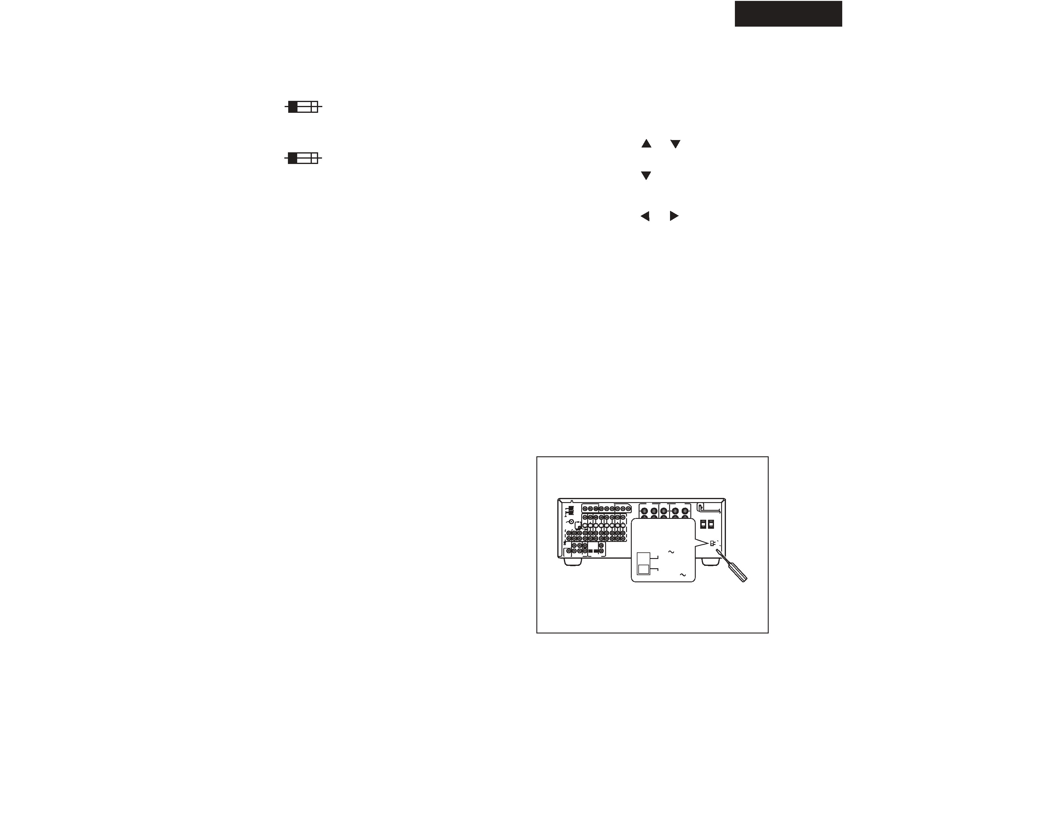
SERVICE PROCEDURES
W
local po
the po
1. Determine the proper v
120 V.
2. If the preset v
driver into the groove
to the right (120
orldwide models are equipped with a voltage selector to conform with
wer supplies. Be sure to set this switch to match the voltage of
wer supply in your area before plugging in the unit.
oltage for your area: 220-230 V or
oltage is not correct for your area, insert a screw-
in the switch. Slide the switch all the way
V) or to the left (220-230 V), whichever is
appropriate.
5.Setting the AM tuning step frequency
(Wolrdwide models only)
6.Setting the Voltage selector (Worldwide models
only)
A
es the contents
ge the
ver a
xposed to a
7. Changing the AM band step
With the exception of the worldwide models,a tuning step step setup
mode is not provided. When you change the band step, change
the parts as shown below.
To 10kHz
To 9kHz
R7780,R7781
330 ohm
Open
R7880,R7881
Open
2.2 kohm
4. Memory Preservation
This unit does not require memory preserv ation batteries.
built-in memory po wer back-up system preserv
of the memory during po wer f ailures and even when the unit is
unplugged. The unit must be plugged in order to char
back-up system.
The memory preserv ation period after the unit has been
unplugged v aries depending on climate and placement of the
unit. On the a verage, memory contents are protected o
period of a fe w weeks after the last time the unit has been
unplugged. This period is shorter when the unit is e
highly humid climate.
2. To initialize the unit
This device employs a microprocessor to perform various
functions and operations. If interference generated by an external
power supply, radio wave, or other electrical source results in
accident which causes the specified operations and functions to
operate abnormally.
To perform a result, please follow the procedure below.
1.Turn POWER to on.
2.Press and hold down the PRESET MEMORY button, then press the
STANDBY button.
After "clear" is displayed, the preset memory and each
mode stored in the memory, such as surround, are
initialized and will return to the factory setting.
3.Disconnect Power supply cord.
3. Safety-check out
(Only U.S.A. model)
After correcting the original service problem, perform the
following safety check before releasing the set to the customer.
Connect the insulating-resistance tester between the plug of power
supply cord and screw on the back panel.
Specifications: 3.3Mohm+/-10% at 500V.
1. Replacing the fuses
This symbol located near the fuses indicates that the
fuse used is fast operating type. For continued protection against
fire hazard, replace with same type fuse. For fuse rating refer to
the marking adjacent to the symbol.
Ce symbole indique que le fusible utlise est a rapide.
Pour une protection permanente, n'untiliser que fusibles de
meme type. Ce darnier est la qu le present symbol est
appse.
CIRCUIT NO.
PART NO.
DESCRIPTION
F901
F902
F903
F9501
CIRCUIT NO.
PART NO.
DESCRIPTION
F901
F902
F903
F9501
Note: <D>:120V model only
<P>: European model only
<WT>: Worldwide model only
<WR>: Asian model only for 230V
<GT>: 220-230V model only
<A>: Australian model only
252198
252077
252075
252160
252075
8A-UL,Fuse <D/WT/WR>
4A-SE-EAK,Fuse <P/WT/WR/A>
2.5A-SE-EAK,Fuse <P/A>
2.5A-UL/T-237,Fuse <D>
2.5A-SE-EAK,Fuse <P/A/WR/WT>
TX-DS696
TX-DS595
252166
252076
252075
252160
252075
6.3A-UL/T237,Fuse <D/WT/WR>
3.15A-SE-EAK,Fuse <P/WT/WR/A/GT>
2.5A-SE-EAK,Fuse <P/A>
2.5A-UL/T-237,Fuse <D>
2.5A-SE-EAK,Fuse <P/A/WR/WT/GT>
CAUTION:
6 OHMS
MIN.
/ SPEAKER
RL
PB
PR
Y
REMOTE
CONTROL
INPUT 1
INPUT 2
OUTPUT
FM
75
AM
ANTENNA
GND
PB
PR
Y
PB
PR
Y
COMPONENT VIDEO
SEE INSTRUCTION MANUAL
FOR CORRECT SETTING.
4 OHMS
MIN.
/ SPEAKER
FRONT
SPEAKERS
CENTER
SPEAKER
ZONE 2
SPEAKERS
R
L
RL
R
L
FRONT
SURR
L
R
1
2
PRE OUT
CENTER
L
R
VIDEO
S VIDEO
VIDEO 1
VIDEO 2
DVD
VIDEO 4
IN
OUT
IN
OUT
IN
IN
IN
MONITOR
OUT
VIDEO 3
L
R
CENTER
SUB
WOOFER
FRONT
SURR
SUBWOOFER
OPTICAL
COAXIAL
1
2
12
PRE OUT
MULTI
CHANNEL INPUT
DIGITAL INPUT
L
R
OUT
IN
PHONO
TAPE
CD
SWITCHED
100W MAX.
AC OUTLET
120V
VOLTAGE
SELECTOR
220-230V
AV RECEIVER
TX-DS696
MODEL NO. /
:
IMPEDANCE SELECTOR
SET BEFORE POWER ON
SURROUND
SPEAKERS
120V
VOLTAGE
SELECTOR
220-230V
The initializing setting is 9 kHz, and this needs only to be changed if you
are using the unit in a 10-kHz region.
1. Press the SETUP button.
Turn the jog dial or press the
and
cursor buttons on the remote
controller to display "3. PREFERENCE."
2. Press the jog dial or ENTER button on the remote controller.
Turn the jog dial or press the
cursor buttons on the remote
controller to display "AM FREQ STEP?".
3.Press the jog dial or ENTER button on the remote controller.
The currently set frequency step appears.
4.Turn the jog dial or press the
and
cursor buttons on the remote
controller to set the frequency.
5. Press the RETURN button.
"AM FREQ STEP?" appears in the FL tube.
To exit the setup mode immediately, press the SETUP button.
TX-DS595/696
STANDBY/ON
STANDBY
OFF
ON
POWER
MASTER VOLUME
BASS
TREBLE
AV RECEIVER
TX-DS
595
PHONES
FM
AM
PHONO
C D
TAPE
CH LEVEL
VIDEO
2
VIDEO
3
VIDEO
1
DVD
VCR
TUNING
PRESET
SMART SCAN NAVIGATOR
PRESET MEMORY
FM MODE
DISPLAY
RT/PTY/TP
PUSH TO ENTER
DSP/MODE ADJ
SETUP
RETURN
AB
SPEAKERS
AUDIO
SELECTOR
ch
ft
DIRECT
DSP
RDS
SLEEP
MEMORY
SPEAKERS
FM MUTE
PCM DIGITAL
TUNED
FM STEREO
dB
STEREO
AB
MPEG
DTS
See illustration below
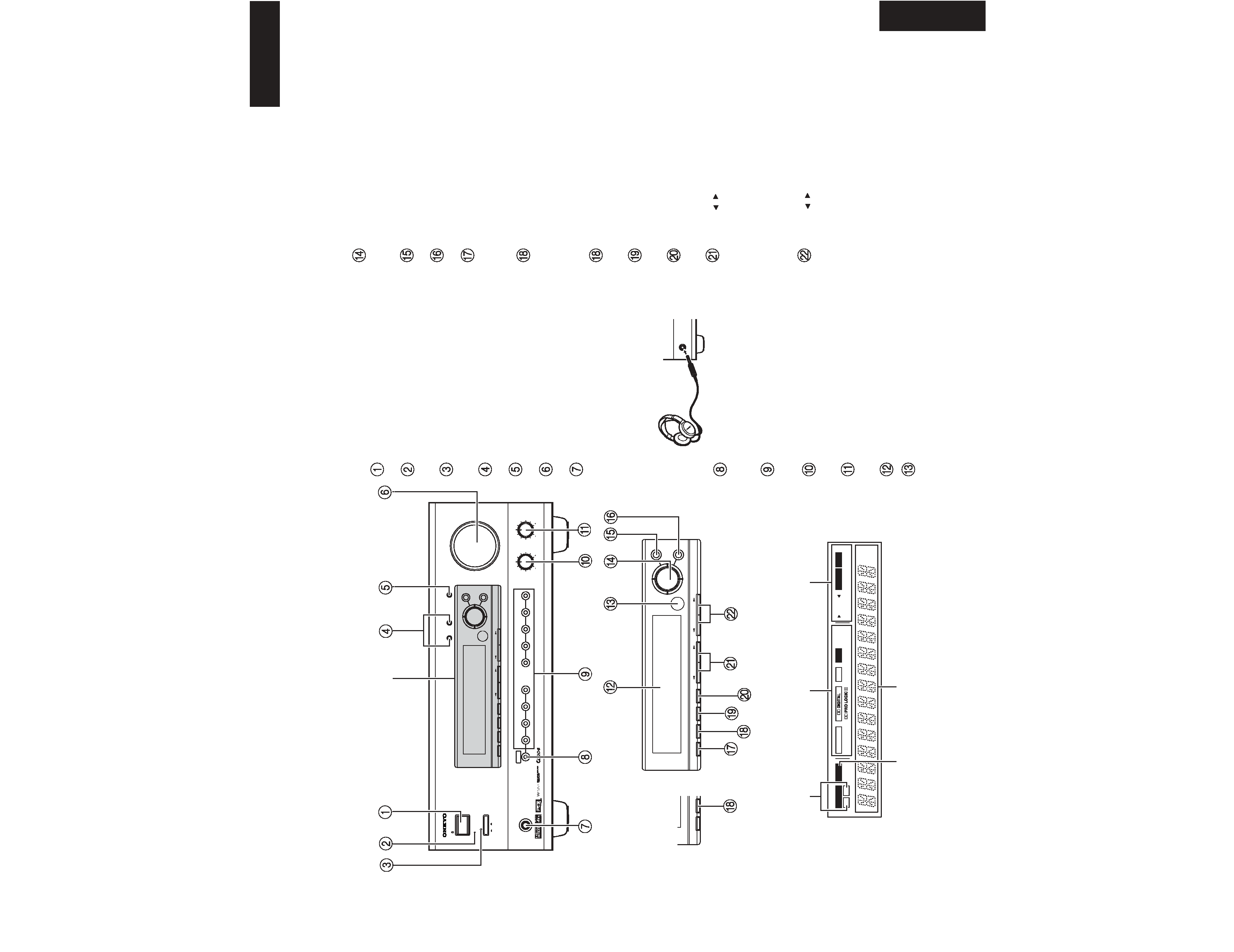
Front panel
Front panel display
TUNING
PRESET
SMART SCAN NAVIGATOR
PRESET MEMORY
FM MODE
DISPLAY
RT/PTY/TP
PUSH TO ENTER
DSP/MODE ADJ
SETUP
RETURN
DISPLAY
DIMMER
For all models other
than European model
Speakers A/B indicators
Sleep indicator
Multi function display
Listening mode or digital input
format indicators
Tuning indicators
7
POWER switch
Turns on and off the main power supply for the TX-DS595.
STANDBY indicator
Lights when the TX-DS595 is in the standby state and flashes when
a signal is received from the remote controller.
STANDBY/ON button
Press to turn on the TX-DS595 when in the standby state. Press again
to return the TX-DS595 to the standby state.
SPEAKERS A/B buttons
Press these buttons to turn on and off speakers systems A and B.
CH LEVEL button
Press to select the channel whose level is to be adjusted.
MASTER VOLUME dial
The MASTER VOLUME dial is used to control the volume.
PHONES jack
To listen with headphones, plug a pair headphones with a standard
stereo plug into the PHONES jack on the TX-DS595 front panel.
When you connect headphones, the unit will enter STEREO mode
automatically and no sound will be heard from the speakers. If you
have selected MULTI CH INPUT, you will hear sound only from the
FRONT L and R channels. Note that the volume level for the
headphones is adjustable.
AUDIO SELECTOR button
This button is used to select the type of audio input signal. Each time
pressed, the setting cycles from "AUTO"
"MULTICH"
"ANALOG" and back.
Input source buttons (DVD, VIDEO 13, TAPE, FM,
AM, PHONO, and CD)
These buttons are used to select the input source.
BASS dial
Boosts or cuts the bass response. Bass adjustment is effective only
for the front speakers and headphones.
TREBLE dial
Boosts or cuts the treble response. Treble adjustment is effective
only for the front speakers and headphones.
Front display
Remote control sensor
PHONES
SMART SCAN NAVIGATOR jog dial and indicators
Used to make settings in the setup display, change listening mode
settings, and more.
SETUP button
Press to enter and exit the setup mode.
RETURN button
Press to move up one level in the setup mode.
DISPLAY button
The DISPLAY button is used to display information about the
current input source signal. Each time you press the display button,
the screen changes to show you different information concerning the
input signal.
RT/PTY/TP (European models only) button
This button is only available on European models. Use this button to
help tune into the Radio Data System (RDS) for FM broadcasting.
RDS was developed within the European Broadcasting Union
(EBU) and is available in most European countries. Each time the
button is pressed, the display changes from RT (radio text) to PTY
(program type) to TP (traffic program) and then back to RT again.
DIMMER (other than European models) button
Press to set the brightness of the front display. There are 3 settings
available: normal, dark, and very dark.
FM MODE button
When there is too much noise in the stereo reception of an FM
broadcast, press to turn off the FM MUTE function.
PRESET MEMORY button
This button is used to assign the radio station that is currently tuned
in to a preset channel or delete a previously preset station.
TUNING
/
buttons
Use these buttons to change the tuner frequency. The tuner
frequency is displayed in the front display and it can be changed in
50 kHz increments for FM and 10 kHz (or 9 kHz) increments for
AM.
When FM is selected, you can hold down one of the tuning buttons
and then release it to activate the auto-search feature. It will search
for a station in the direction of the button you pressed and stop
when it tunes into one.
PRESET
/
buttons
When AM or FM is selected as the input source, press one of these
buttons to jump to a radio station that you preset using the PRESET
MEMORY button. Pressing the right button moves from the most
recently preset station to older ones, and pressing the left button
moves in the reverse order.
TX-DS595
PANEL VIEWS
TX-DS595