CONTENTS
Features.............................................................................................................................................. 2
Important safeguards ......................................................................................................................... 3
Precautions......................................................................................................................................... 3
Before using this unit......................................................................................................................... 4
System connections ........................................................................................................................... 5
Antenna connections.......................................................................................................................... 6
Control positions and names.............................................................................................................. 8
Connecting the power ........................................................................................................................ 9
Receiving stations ............................................................................................................................ 10
Receiving RDS ................................................................................................................................ 13
Entering characters .......................................................................................................................... 15
Setting the clock ............................................................................................................................. 16
Using the timer (for remote control only)........................................................................................ 18
Specifications................................................................................................................................... 20
Troubleshooting guide ..................................................................................................................... 20
T-4711
Instruction Manual
FM Stereo / AM Tuner
All models except European models
(FM Stereo / AM Tuner)
European model
(FM Stereo Tuner)
T-4711
T-4711
FM Stereo Tuner
2
Thank you for your purchase of the Onkyo T-4711 Tuner.
Please read this manual thoroughly before making connections and turning power on.
Following the instructions in this manual will enable you to obtain optimum performance and listening enjoyment from your
new Tuner.
Please retain this manual for future reference.
Supplied accessory
a. 1 Remote control
2 Batteries (Size AA, R6, or UM-3)
b. 1 Remote control cable
c. 1 Audio connection cable
d. 1 T-shaped FM antenna
e. 1 AM loop antenna (For models other than European models)
f. 1 75/300 ohm antenna adaptor
(For models other than European models)
g. 1 Conversion plug (Worldwide model only)
Declaration of Conformity
We, ONKYO EUROPE
ELECTRONICS GMBH
INDUSTRIESTRASSE 18/20
82110 GERMERING,
GERMANY
declare in own responsibility, that the ONKYO product described
in this instruction manual is in compliance with the corresponding
technical standards such as EN55013,EN55020,EN60555-2,
EN60065
GERMERING,GERMANY
ONKYO EUROPE ELECTRONICS GMBH
H. YAMAZOE
a.
b.
c.
d.
e.
f.
g.
Features
s RDS (AF, PS, PTY, TP, RT, CT, TA)
s 40 FM Random presets / 4 Groups
s 3 Modes APR (Auto Precision Reception)
IF Band,
High Blend, Mode
s 4 Groups Memory
s Dial Tuning Knob
s FM Cable with 25kHz step Tuning
s 10-Segment Signal Strength Bar
s 4 Mode Timer Function (Once, WeekDay, WeekEnd,
Sleep)
s ACCUCLOCK
s 7 Remote Compatible
Remarks:
FM & AM available (For USA, Canada and Asia market)
FM only (For Europe market)
q
For models having a power cord with a polarized plug.
CAUTION: TO PREVENT ELECTRIC SHOCK, MATCH
WIDE BLADE OF PLUG TO WIDE SLOT, FULLY INSERT.
q
Sur les modèles dont la fiche est polarisée.
ATTENTION: POUR ÉVITER LES CHOCS ÉLECTRIQUES,
INTRODUIRE LA LAME LA PLUS LARGE DE LA FICHE DANS
LA BORNE CORRESPONDANTE DE LA PRISE ET POUSSER
JUSQU'AU FOND.
FOR CANADIAN MODEL:
(POUR LE MODELE CANADIEN)
Memory Preservation
This unit does not require memory preservation batteries. A built-in
memory power back-up system preserves the contents of the memory
during power failures and even when the unit is unplugged. The unit
must be plugged in order to charge the back-up system.
The memory preservation period after the unit has been unplugged var-
ies depending on climate and placement of the unit. On the average,
memory contents are protected over a period of a few weeks after the
last time the unit has been unplugged. This period is shorter when the
unit is exposed to a highly humid climate.
"WARNING"
"TO REDUCE THE RISK OF FIRE OR ELECTRIC SHOCK,
DO NOT EXPOSE THIS APPLIANCE TO RAIN OR MOIS-
TURE."
CAUTION:
"TO REDUCE THE RISK OF ELECTRIC SHOCK, DO NOT
REMOVE COVER (OR BACK). NO USER-SERVICEABLE
PARTS INSIDE. REFER SERVICING TO QUALIFIED SER-
VICE PERSONNEL."
q
The lightning flash with arrowhead symbol, within
an equilateral triangle, is intended to alert the user
to the presence of uninsulated "dangerous voltage"
within the product's enclosure that may be of suffi-
cient magnitude to constitute a risk of electric shock
to persons.
q
The exclamation point within an equilateral triangle
is intended to alert the user to the presence of
important operating and maintenance (servicing)
instructions in the literature accompanying the
product.
CAUTION
RISK OF ELECTRIC SHOCK
DO NOT OPEN
3
Important safeguards
1.
Read Instructions All the safety and operating instructions should be
read before the appliance is operated.
2.
Retain Instructions The safety and operating instructions should be
retained for future reference.
3.
Heed Warnings All warnings on the appliance and in the operating
instructions should be adhered to.
4.
Follow Instructions All operating and use instructions should be fol-
lowed.
5.
Water and Moisture The appliance should not be used near water
for example, near a bathtub, washbowl, kitchen sink, laundry tub, in a wet
basement, or near a swimming pool, and the like.
6.
Carts and Stands The appliance should be used only with a cart or
stand that is recommended by the manufacturer.
7.
Wall or Ceiling Mounting The appliance should be mounted to a
wall or ceiling only as recommended by the manufacturer.
8.
Ventilation The appliance should be situated so that its location or
position does not interfere with its proper ventilation. For example, the
appliance should not be situated on a bed, sofa, rug, or similar surface that
may block the ventilation openings; or if placed in a built-in installation,
such as a book case or cabinet that may impede the flow of air through the
ventilation openings, there should be free space of at least 20 cm and open
up behind the appliance.
9.
Heat The appliance should be situated away from heat sources such as
radiators, heat registers, stoves, or other appliances (including amplifiers)
that produce heat.
10.
Power Sources The appliance should be connected to a power supply
only of the type described in the operating instructions or as marked on the
appliance.
11.
Polarization If the appliance is provided with a polarized plug having
one blade wider than the other, please read the following information: The
polarization of the plug is a safety feature. The polarized plug will only fit
the outlet one way. If the plug does not fit fully into the outlet, try revers-
ing it. If there is still trouble inserting it, the user should seek the services
of a qualified electrician. Under no circumstances should the user attempt
to defeat the polarization of the plug.
12.
Power-Cord Protection Power-supply cords should be routed so that
they are not likely to be walked on or pinched by items placed upon or
against them, especially near plugs, convenience receptacles, and the point
where they exit from the appliance.
13.
Cleaning The appliance should be cleaned only as recommended by
the manufacturer.
14.
Power Lines An outdoor antenna should be located away from power
lines.
15.
Nonuse Periods The power cord of the appliance should be unplugged
from the outlet when left unused for a long period of time.
16.
Object and Liquid Entry Care should be taken so that objects do not
fall and liquids are not spilled into the enclosure through openings.
17.
Damage Requiring Service The appliance should be serviced by
qualified service personnel when:
A. The power-supply cord or the plug has been damaged; or
B. Objects have fallen, or liquid has been spilled into the appliance; or
C. The appliance has been exposed to rain; or
D. The appliance does not appear to operate normally or exhibits a
marked change in performance; or
E. The appliance has been dropped, or the enclosure damaged.
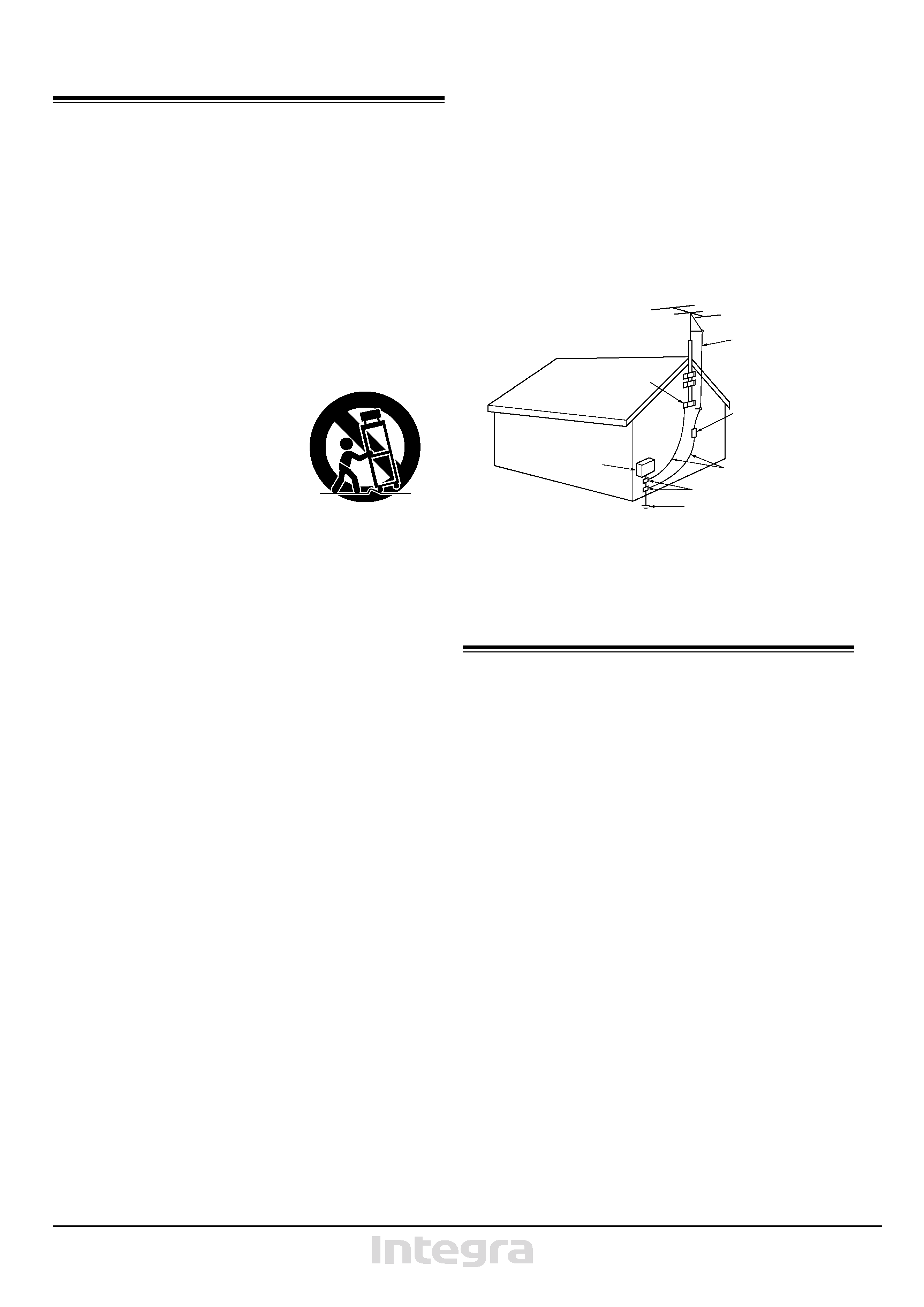
6A. An appliance and cart combination
should be moved with care. Quick
stops, excessive force, and uneven
surfaces may cause the appliance
and cart combination to overturn.
PORTABLE CART WARNING
S3125A
18.
Servicing The user should not attempt to service the appliance beyond
that described in the operating instructions. All other servicing should be
referred to qualified service personnel.
19.
Outdoor Antenna Grounding If an outside antenna is connected to
the receiver, be sure the antenna system is grounded so as to provide some
protection against voltage surges and built up static charges. Article 810 of
the National Electrical Code, ANSI/NFPA 70, provides information with
regard to proper grounding of the mast and supporting structure, ground-
ing of the lead-in wire to an antenna discharge unit, size of grounding con-
ductors, location of the antenna-discharge unit, connection to grounding
electrodes, and requirements for the grounding electrode. See Figure 73.1.
FIGURE 73.1:
EXAMPLE OF ANTENNA GROUNDING AS PER NATIONAL ELEC-
TRICAL CODE
Precautions
1. Warranty Claim
You can find the serial number of the rear panel. In case of warranty
claim, please report this number.
2. Care
From time to time you should wipe the front and rear panels and the
cabinet with a soft cloth. For heavier dirt, dampen a soft cloth in a
weak solution of mild detergent and water, wring it out dry, and wipe
off the dirt. Following this, dry immediately with a clean cloth. Do not
use rough material, thinners, alcohol or other chemical solvents or
cloths since these could damage the finish or remove the panel letter-
ing.
3. Power
WARNING
BEFORE PLUGGING IN THE UNIT FOR THE FIRST TIME,
READ THE FOLLOWING SECTION CAREFULLY.
q
Some models are designed for use only with the power supply
voltage of the region where they are sold.
U.S.A. and Canadian models:
AC 120 V, 60 Hz
European model:
AC 230 V, 50 Hz
Worldwide model:
AC 120 V/220 230 V switchable,
50/60 Hz
q
Voltage Selector (Rear Panel)
Worldwide models are equipped with a voltage selector to con-
form with local power supplies. Be sure to set this switch to match
the voltage of the power supply in your area before turning the
power button on. (See "Setting the voltage selector and Tuning
step frequency (Worldwide models only)", P. 4.) Models without a
voltage selector can only be used in areas where the power supply
is the same as that of the unit.
GROUND
CLAMP
ELECTRIC
SERVICE
EQUIPMENT
POWER SERVICE GROUNDING
ELECTRODE SYSTEM
(NEC ART 250, PART H)
GROUND CLAMPS
GROUNDING CONDUCTORS
(NEC SECTION 810-21)
ANTENNA
DISCHARGE UNIT
(NEC SECTION 810-20)
ANTENNA
LEAD IN
WIRE
NEC NATIONAL ELECTRICAL CODE
S2898A
4
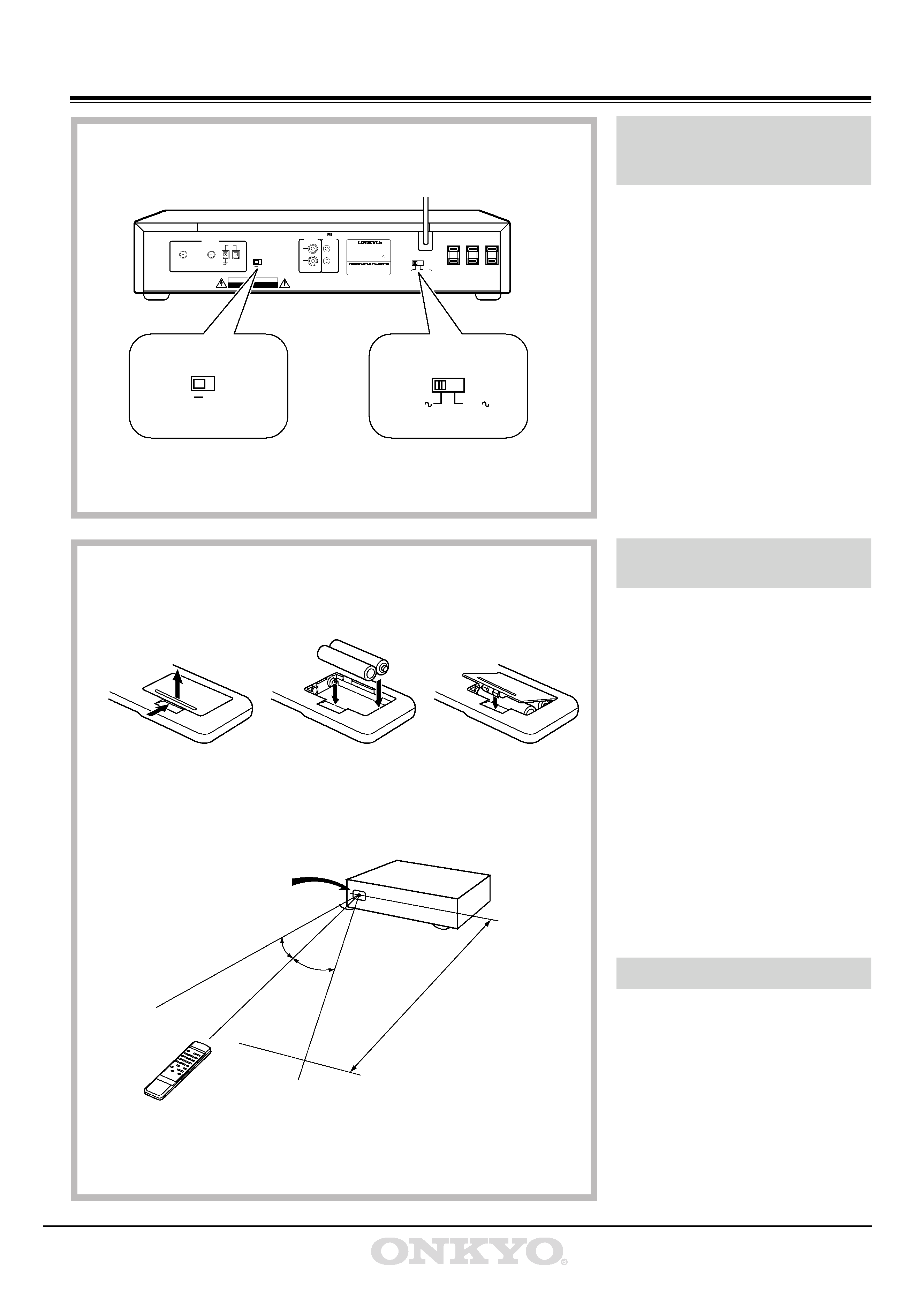
Before using this unit
Voltage selector
1. Determine the proper voltage for your area:
220 230 V or 120 V.
2. If the preset voltage is not correct for your
area, insert a screwdriver into the groove
in the switch. Slide the switch all the way
to the right (120 V) or to the left (220
230 V), whichever is appropriate.
Tuning step frequency
Wooldwide models are equipped with a
switch that controls the AM (9 kHz/10 kHz)
and FM (50 kHz/200 kHz) bands tuning
steps. Please set this switch to match the tun-
ing step frequency in your area.
U.S.A.
: AM 10 kHz, FM 200 kHz
(25 kHz, Fine mode)
Other areas : AM 9 kHz, FM 50 kHz
(25 kHz, Fine mode)
Remove the battery compartment cover by
opening it as shown in the illustration. Load
three R6 (UM-3) AA size batteries into the
remote control with the plus (+) and minus
() terminals positioned as indicated by the
diagram inside the battery compartment and
close the cover.
q
Remove dead batteries immediately to
avoid corrosion damage.
q
To avoid potential corrosion damage,
never mix old batteries with new ones.
q
The manganese batteries supplied with
this unit have a service life of approxi-
mately six months, depending on fre-
quency of usage.
q
This unit comes equipped with R6 (UM-
3) AA manganese batteries, but we rec-
ommend that long-life alkaline batteries
LR6 (AM-3) AA be used when replacing
the batteries.
The following information will help you get
optimum use from the remote control.
q
Place this unit away from direct bright
light, which can prevent proper operation
of the remote control.
q
Make sure audio rack doors do not have
coloured glass. If this unit is placed
behind such a door, this may prevent
proper remote control operation.
q
Using other remote controls in the same
room as this unit remote control may
cause interference.
Setting the voltage selector
and Tuning step frequency
(Worldwide models only)
Inserting the remote control
batteries
Using the remote control
VOLTAGE SELECTOR
220-230V
120V
FREQ. STEP
USA
OTHER
WARNING
RISK OF ELECTRIC SHOCK
DO NOT OPEN
RISQUE DE CHOC ELECTRIQUE
NE PAS OUVRIR
AVIS
OUTPUT
REMOTE
CONTROL
L
R
FM STEREO / AM TUNER
MODEL NO.
T-4711
RATING: AC120/220-230V
50/60Hz
12W
2-1,NISSHIN-CHO,NEYAGAWA-SHI,OSAKA,
JAPAN
MADE IN JAPAN
AC OUTLETS
SWITCHED
TOTAL 500W MAX.
AB
FM75
ANTENNA
AM
FREQ. STEP
USA
OTHER
VOLTAGE SELECTOR
220-230V
120V
12
3
-
+
+
-
-
30°
30°
T-4711
Please insert the batteries into the remote control according to the illustration.
Remote control
Remote control sensor
approx. 5m
5
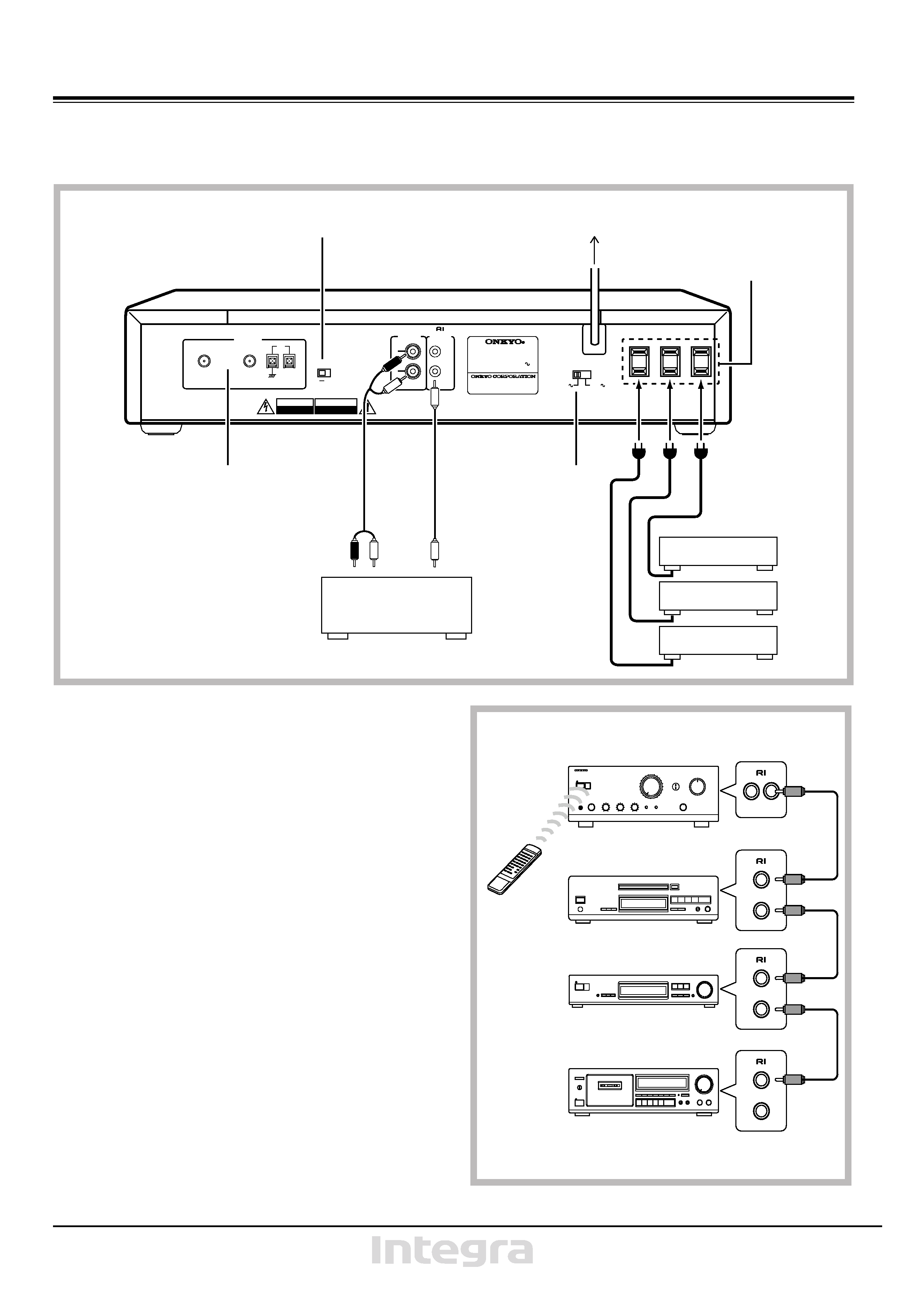
System connections
q
Do not plug in the power cord until all connections have been made.
q
On each pair of input or output jacks, the lower jack (marked R) corresponds to the right channel, and the upper jack (marked L) to the left
channel.
VOLTAGE SELECTOR
220-230V
120V
FREQ. STEP
USA
OTHER
WARNING
RISK OF ELECTRIC SHOCK
DO NOT OPEN
RISQUE DE CHOC ELECTRIQUE
NE PAS OUVRIR
AVIS
OUTPUT
REMOTE
CONTROL
L
LR
R
FM STEREO / AM TUNER
MODEL NO.
T-4711
RATING: AC120/220-230V
50/60Hz
12W
2-1,NISSHIN-CHO,NEYAGAWA-SHI,OSAKA,
JAPAN
MADE IN JAPAN
AC OUTLETS
SWITCHED
TOTAL 500W MAX.
AB
FM75
ANTENNA
AM
Antenna connection
(See pages 6-7.)
Amplifier
Tuning Step Frequency
(See page 4. Worldwide model only)
To wall outlet
Configuration and the number
of outlets may vary depending
on places of destination.
Voltage selector
(See page 4. World
wide model only)
13
2
1 Connecting the amplifier:
Connect the tuner's OUTPUT jacks and the amplifier's INPUT jacks
using the audio connection cable. Refer to the amplifier's instruction
manual for connections.
2 AC outlets (SWITCHED)
The shape, orientation, the number and total capacity of the AC outlets
may differ according to the model and the area where the unit is pur-
chased. Be careful that other components connected to this unit do not
exceed the capacity that is printed on the rear panel below under the
AC outlets.
When connecting other Integra series components (such as the A-
9911/9711, DX-7911/7711 or TA-6711), connect the power cords of
those components to this unit's AC outlets.
The unit may be turned ON or OFF according to the setting of
POWER button, ON or OFF, respectively.
When this unit is used as a timer, the other components that will be
switched on and off should be connected to this unit's AC outlets.
3 Connections for remote control
When this is connected to an amplifier with the Onkyo 7 jack, you
are able to operate it by pressing the TUNER buttons on the amplifi-
er's supplied remote control.
NOTE:
An 7 remote control cable equipped with a 1/8
(3.5 mm) diameter
miniature two-conductor phone plug is included with this unit and
with every compact disc player and cassette deck with the 7 mark.
T-4711
A-9711
Amplifier
CD player
Cassettedeck