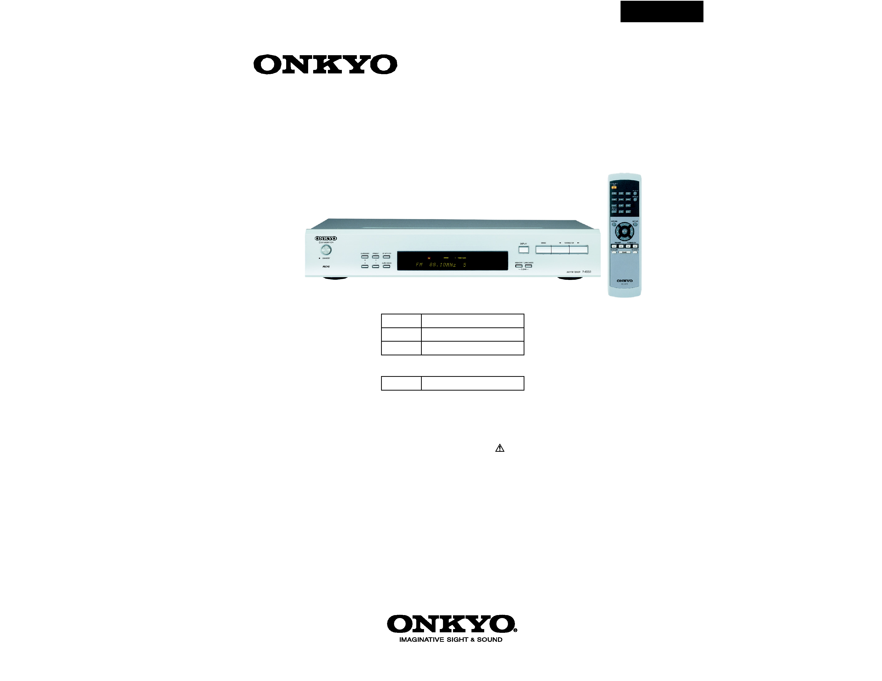
T-4555/4555P
SERVICE MANUAL
SERVICE MANUAL
RC-671T
AM/FM or AM/FM/DAB TUNER
T-4555 : Black and Silver models
MODEL
T-4555
Ref. No. 3956
092006
120V AC, 60Hz
B MDD
230V AC, 50Hz
230V AC, 50Hz
230V AC, 50Hz
B MPP
S MPP
S MPB
MULTI-PLATFORM TUNER
MODEL
T-4555P
T-4555P : Black model
SAFETY-RELATED COMPONENT
WARNING!!
COMPONENTS IDENTIFIED BY MARK
ON THE
SCHEMATIC DIAGRAM AND IN THE PARTS LIST ARE
CRITICAL FOR RISK OF FIRE AND ELECTRIC SHOCK.
REPLACE THESE COMPONENTS WITH ONKYO
PARTS WHOSE PART NUMBERS APPEAR AS SHOWN
IN THIS MANUAL.
MAKE LEAKAGE-CURRENT OR RESISTANCE
MEASUREMENTS TO DETERMINE THAT EXPOSED
PARTS ARE ACCEPTABLY INSULATED FROM THE
SUPPLY CIRCUIT BEFORE RETURNING THE
APPLIANCE TO THE CUSTOMER.
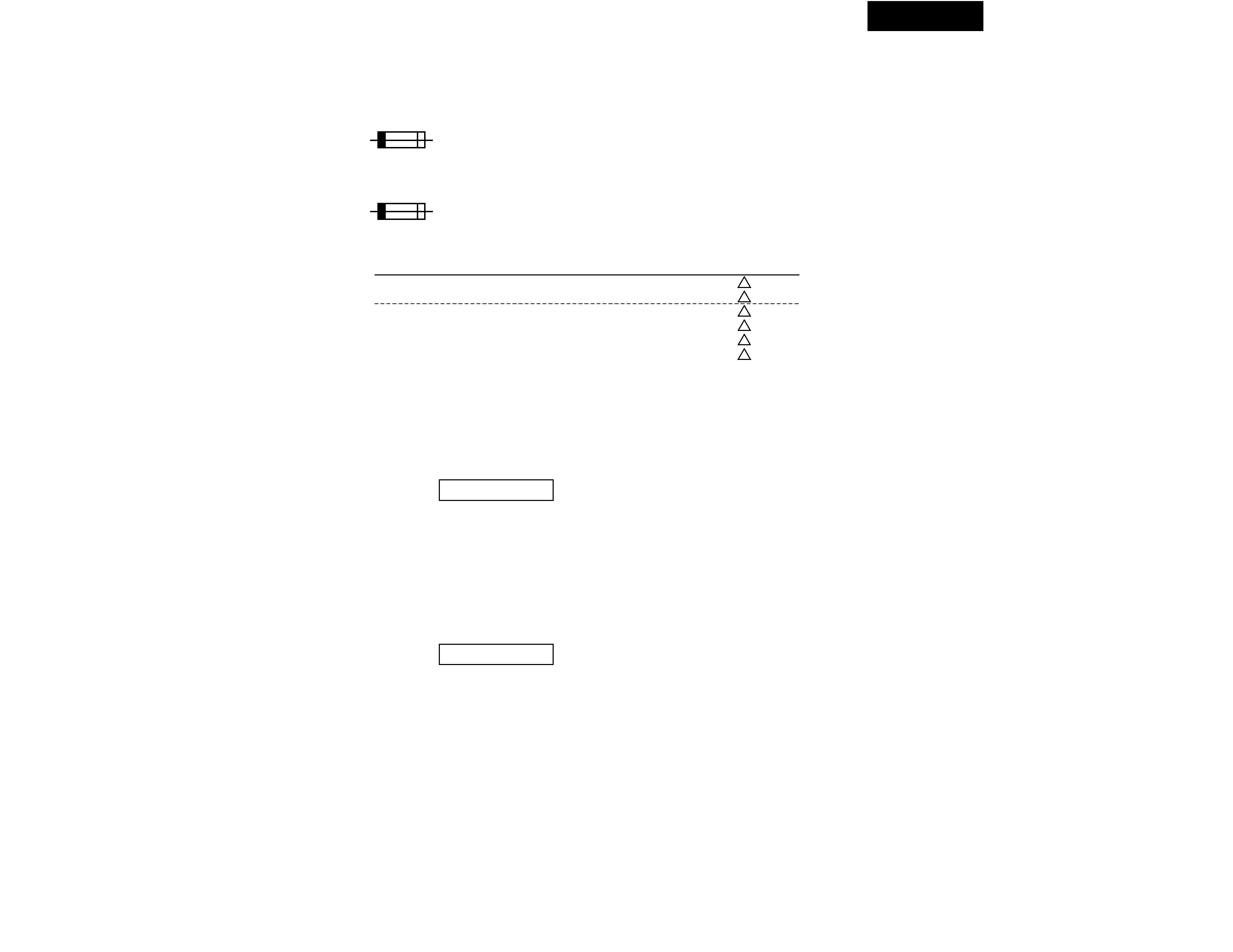
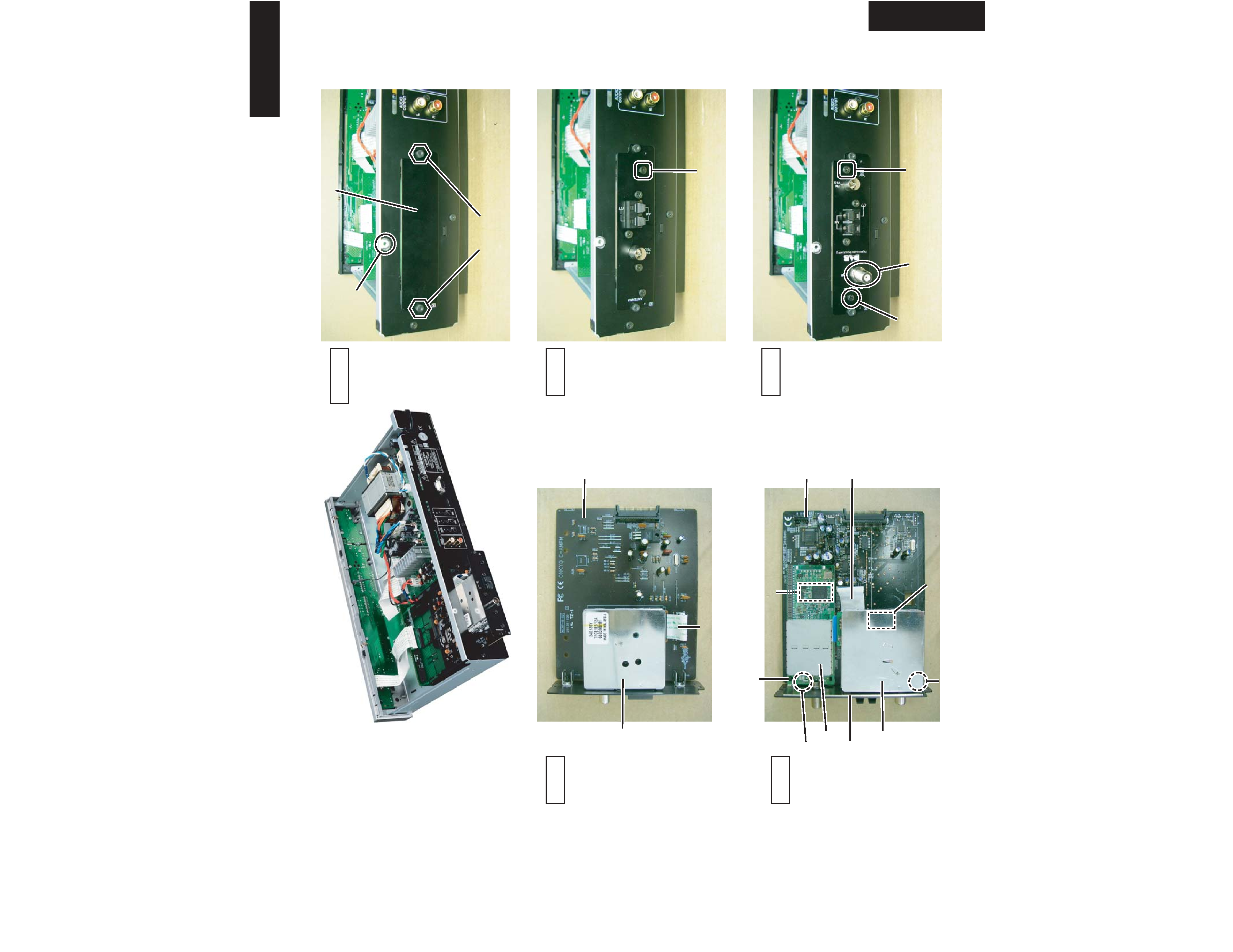
SERVICE PROCEDURE-1
T-4555/4555P
V.1.02/06823A-3
Clear
---> STANDBY
!
!
!
!
!
!
1. Replacing the fuse
REF. NO.
F901
F901 or
F901
F901 or
F901
F901 or
PART NAME
FUSE
FUSE
FUSE
FUSE
FUSE
FUSE
DESCRIPTION
1.25A-UL/T-233
1.25A-T/UL-ST2
1.25A-SE-EAWK FUSE
1.25A-SE-TL250V
1.25A-SE-EAWK FUSE
1.25A-SE-TL250V
This symbol located near the fuse indicates that the
fuse used is show operating type, For continued protection against
fire hazard, replace with same type fuse , For fuse rating, refer to
the marking adjacent to the symbol.
Ce symbole indique que le fusible utilise est e lent.
Pour une protection permanente, n'utiliser que des fusibles de meme
type. Ce demier est indique la qu le present symbol est apposre.
PART NO. (SN)
252318GR
252251GR
252071GR
252272GR
252071GR
252272GR
3. Check the version of microprocessor
(1) Connect the AC power cord into a wall outlet.
(2) Press the STANDBY/ON button to turn on the unit.
(3) Press and hold down the DISPLAY button, then press the STANDBY/ON button.
(4) Press the STANDBY/ON button to turn off the unit.
(5) Disconnect the AC power cord from a wall outlet.
version
3 seconds
FL display
REMARKS
P<MDD>
P<MDD>
<MPP>
<MPP>
<MPB>
<MPB>
2. Initialize the unit
(1) Connect the AC power cord into a wall outlet.
(2) Press the STANDBY/ON button to turn on the unit.
(3) Press and hold down the MEMORY button, then press the STANDBY/ON button.
(4) Disconnect the AC power cord from a wall outlet.
FL display
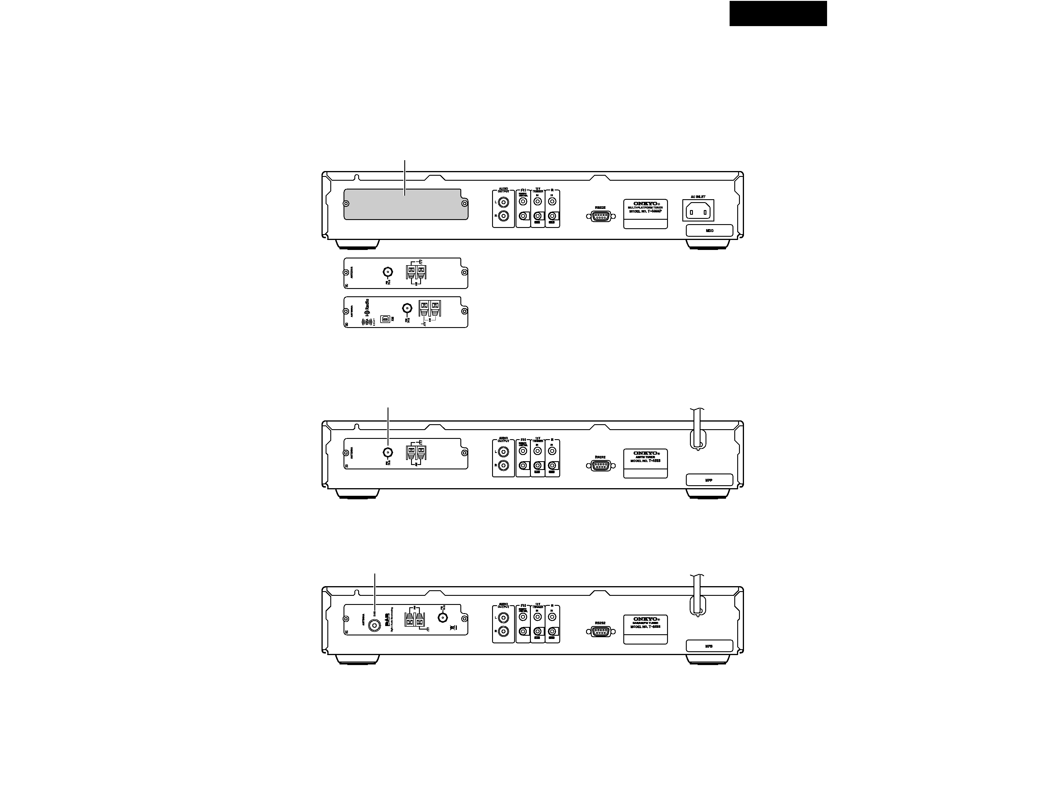
SERVICE PROCEDURE-2
T-4555/4555P
Product number: C-AMFM
AM/FM tuner
Product number: C-HDXM
HD Radio AM/FM tuner, and XM Satellite Radio tuner
Board slot
4. Tuner boards
USA model <MDD>
The following optional tuner boards are available for the T-4555P.
European model <MPP>
Comes with C-AMFM tuner board installed.
U.K. model <MPB>
Comes with C-DAB tuner board installed.
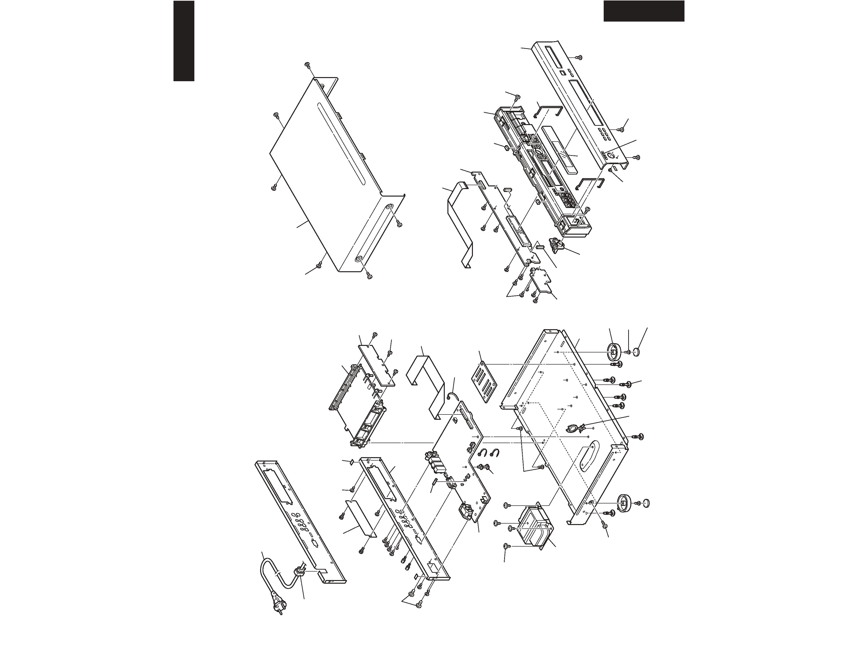
EXPLODED VIEWS-1
OVERALL
T-4555/4555P
T-4555/4555P
A015
x 2 pcs.
A002
x 4 pcs.
A004
x 4 pcs.
A006
x 4 pcs.
A021
x 4 pcs.
A003
x 4 pcs.
A008
x 7 pcs.
A019
x 2 pcs.
A018
x 2 pcs.
A404
x 3 pcs.
A016
x 2 pcs.
A017
x 10 pcs.
A045
x 3 pcs.
A412
x 9 pcs.
A411a
x 2 pcs.
P<MDD>
A022
x 3 pcs.
A051
x 6 pcs.
P112
P111
U02
U03
U05
U04
U01
A050
A020
A413
x 2 pcs.
A410
A400
A010
A401
A014
A402
A009
A001
A007
F901
T901
A011
A023
A411b
<MPP, MPB>
P901
<MPP, MPB>
" Refer
to
EXPLODED
VIEWS
-2 "
EXPLODED VIEWS-2
TUNER PC BOARD
T-4555/4555P
T-4555/4555P
A414
A421
x 2 pcs.
A422
x 3 pcs.
A428 (washer)
A429 (nut)
A424
U06
U08
U08
U09
A424
A425
P908
P910
A430
A431
A432 (Rivet)
A426 (Rivet)
A427 (Spacer)
A422
x 5 pcs.
U07
A420
--- Rear side ---
" Tuner PC board "
P<MDD>
<MPP>
<MPB>
<MPP>
<MPB>