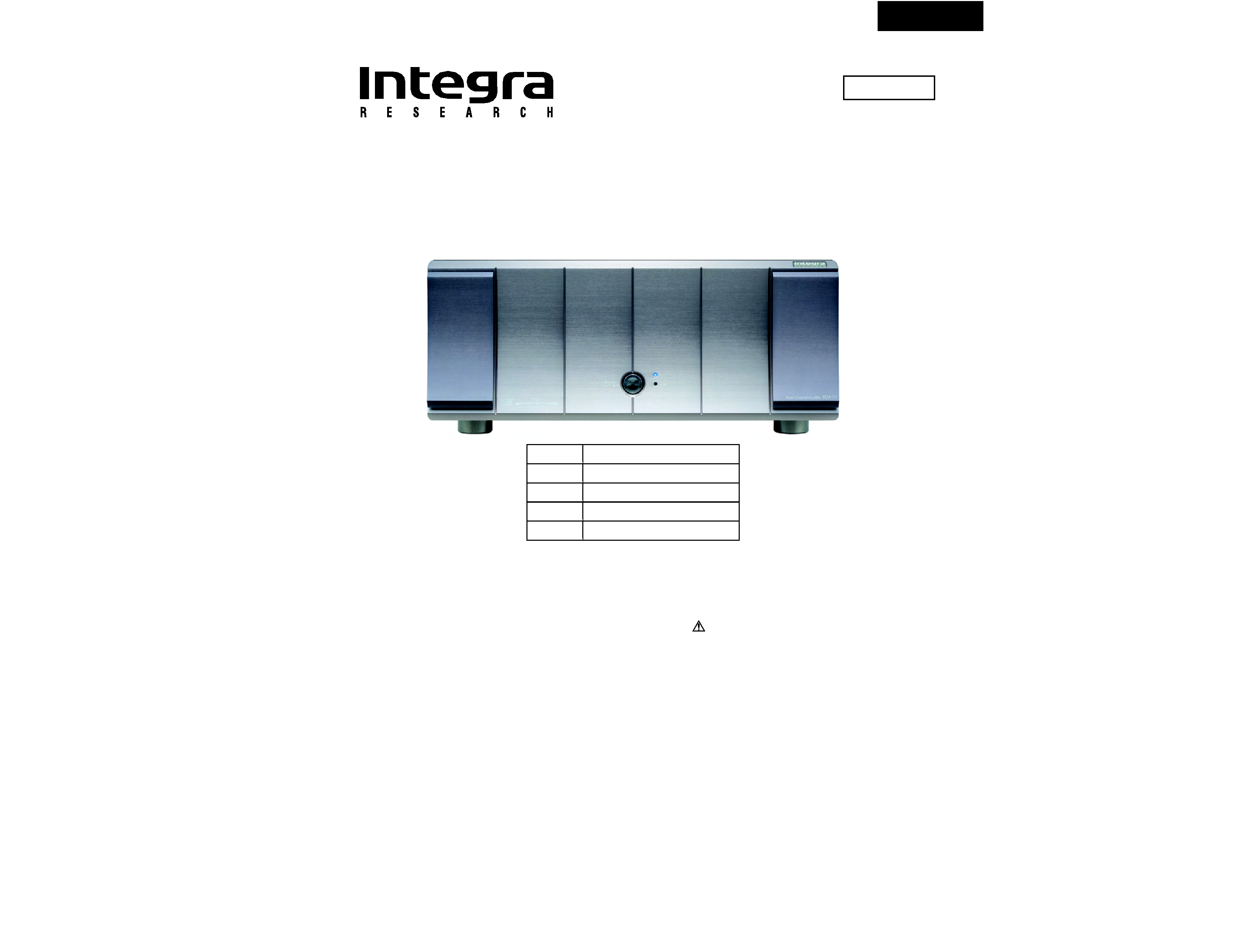
RDA-7.1
SERVICE MANUAL
SERVICE MANUAL
SEVEN CHANNEL AMPLIFIER
MODEL
RDA-7.1
120 V AC, 60Hz
ADD
Ref. No. 3804
Nov, 2004
230-240 V AC, 50Hz
APP
230-240 V AC, 50Hz
APA
220-230 V AC, 50/60Hz
AGT
220-230 V AC, 50/60Hz
AGK
SAFETY-RELATED COMPONENT
WARNING!!
COMPONENTS IDENTIFIED BY MARK
ON THE
SCHEMATIC DIAGRAM AND IN THE PARTS LIST ARE
CRITICAL FOR RISK OF FIRE AND ELECTRIC SHOCK.
REPLACE THESE COMPONENTS WITH ONKYO
PARTS WHOSE PART NUMBERS APPEAR AS SHOWN
IN THIS MANUAL.
MAKE LEAKAGE-CURRENT OR RESISTANCE
MEASUREMENTS TO DETERMINE THAT EXPOSED
PARTS ARE ACCEPTABLY INSULATED FROM THE
SUPPLY CIRCUIT BEFORE RETURNING THE
APPLIANCE TO THE CUSTOMER.

RDA-7.1
SPECIFICATIONS
AMPLIFIER SECTION
Number of channels :
Power :
Frequency response at -3 dB :
Input Impedance :
Input signal for max output power :
Input Sensitivity (Unbalanced) :
Input Sensitivity (Balanced) :
THD :
Damping Factor :
Power consumption
USA, Canada and some Asian model :
Other models :
Rated Speaker Impedance :
GENERAL
Power Supply :
Dimensions (W x H x D) :
Weight :
7
150 watts per channel min. RMS at 8 ohms, 2 channels
driven from 20 Hz to 20 kHz with no more than 0.1 % total
harmonic distortion (FTC).
300 watts per channel min. RMS at 4 ohms, 2 channels
driven at 1 kHz with no more than 0.1 % total harmonic
distortion (FTC).
350 W (EIAJ, 4 ohm, 1 kHz, 10 %)
300 W (DIN, 4 ohm, 1 kHz, 0.7 %)
3.5 Hz - 250 kHz
47 kohm each phase
1.2 V
100 mVrms
200 mV
0.03 % (20 Hz to 20 kHz)
40 at 8 ohm
15 A
10 A
4 ohms
AC 120 V, 60 Hz
AC 230 V, 50 Hz
AC 220 V, 50/60 Hz
450 x 197 x 602 mm
17-11/16" x 7-3/4" x 23-11/16"
52.5 kg, 115.7 lbs.
Specifications and features are subject to change without notice.
Power supply and voltage vary depending on the area in which the unit is purchased.

RDA-7.1
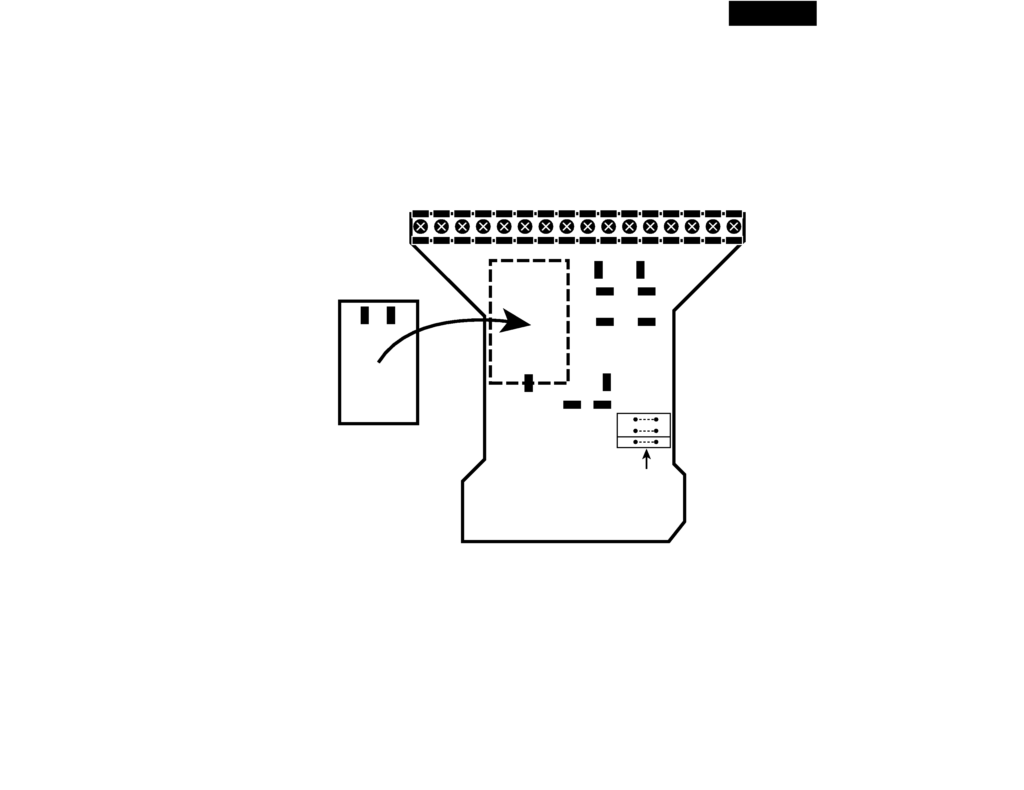
SERVICE PROCEDURE-1
PRIMARY CONNECTIONS FOR DIFFERENT VOLTAGES
AC Board Jumpers
For voltages in the 100V - 120V range, install the two jumpers marked L.
For voltages in the 200V - 240V range, install the single jumper marked H.
Main Transformer Jumpers
The following connections should be made for different line voltages.
100V :
K1-3 to TB1-4
P7
to TB1-3
P2
to TB1-2
K2-3 to TB1-12
P8
to TB1-11
P3
to TB1-10
110V :
K1-3 to TB1-6
P7
to TB1-5
P2
to TB1-2
K2-3 to TB1-14
P8
to TB1-13
P3
to TB1-10
120V :
K1-3 to TB1-8
P7
to TB1-7
P2
to TB1-2
K2-3 to TB1-16
P8
to TB1-15
P3
to TB1-10
200V :
K1-3
to TB1-4
TB1-2
to TB1-3
K2-3
to TB1-12
TB1-10 to TB1-11
220V :
K1-3
to TB1-6
TB1-2
to TB1-5
K2-3
to TB1-14
TB1-10 to TB1-13
230V :
K1-3
to TB1-6
TB1-2
to TB1-7
K2-3
to TB1-14
TB1-10 to TB1-15
240V :
K1-3
to TB1-8
TB1-2
to TB1-7
K2-3
to TB1-16
TB1-10 to TB1-15
RDA-7.1
SERVICE PROCEDURE-2
PRIMARY CONNECTIONS FOR DIFFERENT VOLTAGES (Continued)
Inrush Current Limiter Board
(RDA-7-030-A)
AC Board (RDA-7-020-B)
P2
TB1
P3
P7
P4
P9
P1
P10
P8
K1-3
K2-3
K2-4
K1-4
1 2 3 4 5 6 7 8 9 10 11 12 13 14 15 16
Low
L
L
H
High
Jumpers
RDA-7.1
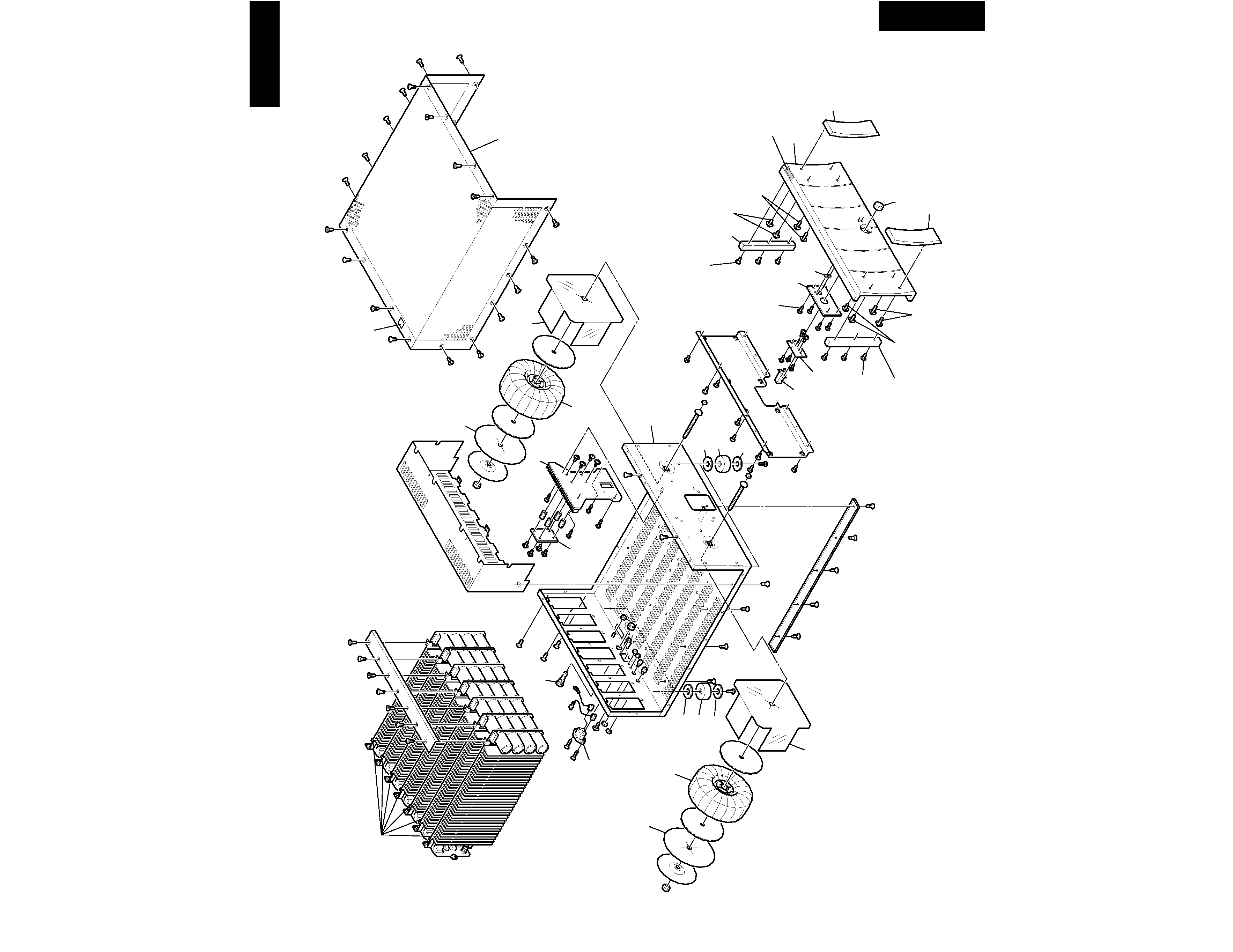
EXPLODED VIEWS-1
OVERALL
RDA-7.1
B06
A50
B03
A51
A50
A51
B04
A06
x 3 pcs.
A05
A08
(14mm)
x 2 pcs.
A07
(10mm)
x 2 pcs.
A03
A23
A04
A02
A07
(10mm)
x 2 pcs.
A08
(14mm)
x 2 pcs.
A05
A06
x 3 pcs.
A22
x 4 pcs.
A21
A20
B02
UN02
A35
UN01
A34
B01
B07
UN03
A34
A35
A10
<Note>
A01 (Front panel ass'y) = A02 --- A08
A635
B08
A52
A52
B05