HT-R940
SERVICE MANUAL
SERVICE MANUAL
AV RECEIVER
Black and Silver models
MODEL
HT-R940
Ref. No. 3960
062006
120V AC, 60Hz
230-240V AC, 50Hz
B MDC
B MPP, S MPP
MUTING
PREVIOUS
MENU
GUIDE
TOP MENU
SP A / B
SETUP
RETURN
PLAYLIST/CAT
PLAYLIST/CAT
RANDOM
SUBTITLE
PLAY MODE
AUDIO
REPEAT
RC-
650M
--/---
TAPE
M D/CDR
HDD
CABLE
ON/STANDBY
DIMMER
ENT
D TUN
SLEEP
10
11
12
INPUT SELECTOR
HDD
DVD
VCR
REMOTE MODE
V
1
V
2
V
3
CD
TAPE
TUNER
DVD
MULTI CH
LISTENING MODE
TV
DISPLAY
TEST TONE
CH SEL
SURROUND
STEREO
Re-EQ
LEVEL+
LEVEL-
L NIGHT
VOL
VOL
SAT
VCR
TV
DVD
RECEIVER
CD
INPUT
+10
0
CLR
12
3
45
6
789
ENTER
CH
DISC
ALBUM
RC-650M
MASTER VOLUME
VIDEO
STANDBY
TONE
DISPLAY
THX
DIMMER
MEMORY
DIGITAL
INPUT
TUNING
MODE
AB
SPEAKERS
TUNER
TAPE
VIDEO
3
VIDEO
2
VIDEO
1
VCR
DVD
MULTI CH
C D
SETUP
RETURN
CLEAR
LISTENING MODE
AUDIO
LR
VIDEO
3 INPUT
STANDBY/ON
PHONES
TUNING
PRESET
ENTER
SAFETY-RELATED COMPONENT
WARNING!!
COMPONENTS IDENTIFIED BY MARK
ON THE
SCHEMATIC DIAGRAM AND IN THE PARTS LIST ARE
CRITICAL FOR RISK OF FIRE AND ELECTRIC SHOCK.
REPLACE THESE COMPONENTS WITH ONKYO
PARTS WHOSE PART NUMBERS APPEAR AS SHOWN
IN THIS MANUAL.
MAKE LEAKAGE-CURRENT OR RESISTANCE
MEASUREMENTS TO DETERMINE THAT EXPOSED
PARTS ARE ACCEPTABLY INSULATED FROM THE
SUPPLY CIRCUIT BEFORE RETURNING THE
APPLIANCE TO THE CUSTOMER.
HT-R940
SERVICE PROCEDURE
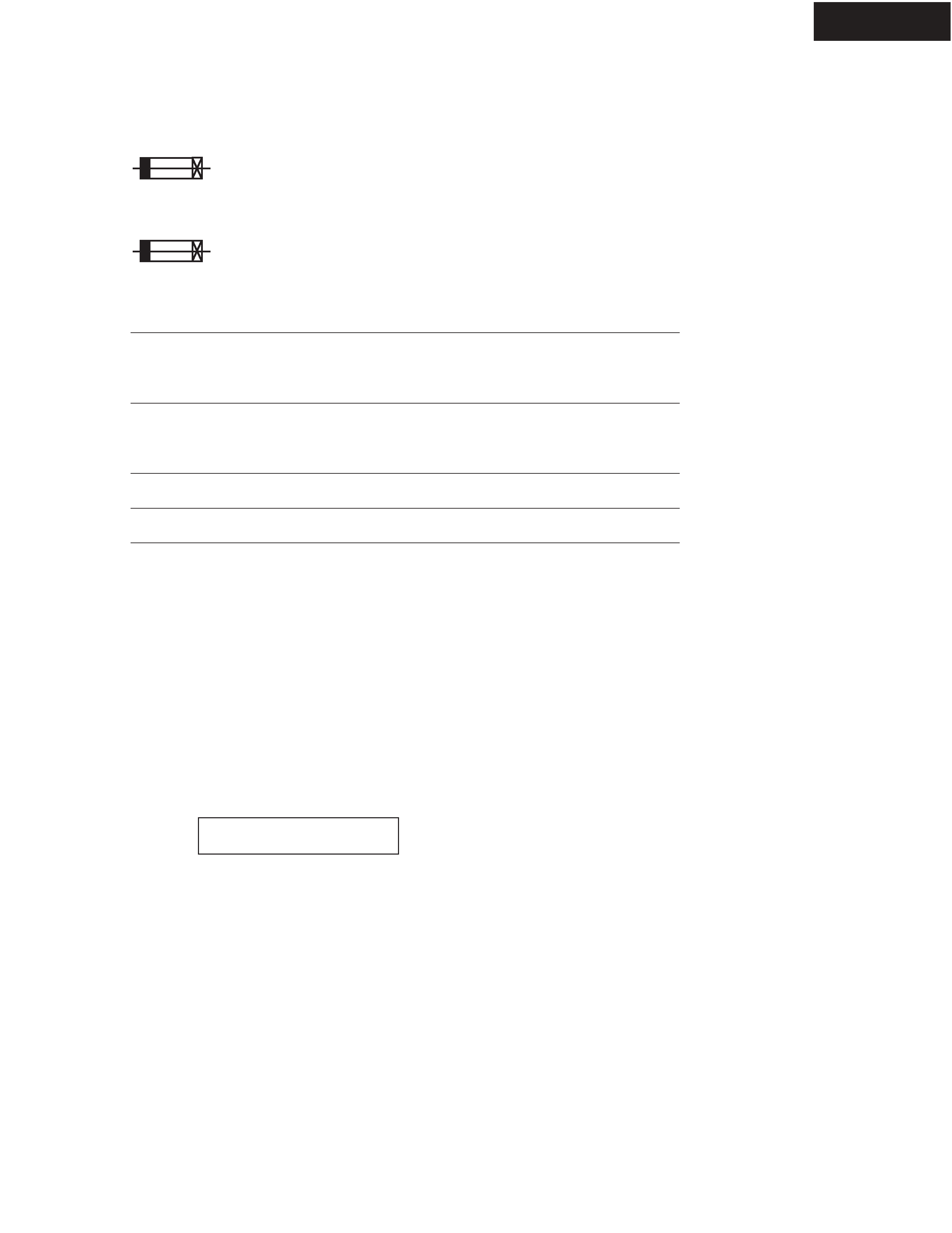
1. Replacing the fuses
This symbol located near the fuse indicates that the
fuse used is slow operating type. For continued protection against
fire hazard, replace with same type fuse. For fuse rating, refer to
the marking adjacent to the symbol.
Ce symbole indique que le fusible utilise est e lent.
Pour une protection permanente, n'utiliser que des fusibles de meme
type. Ce demier est indique la qu le present symbol est appose.
2. To initialize the unit
1. Press and hold down VIDEO 1/VCR button, then press STANDBY/ON button when the unit is powered on.
2. After " Clear " is displayed, the preset memory and each mode stored in the memory, are initialized and
will return to the factory settings.
4. Memory Backup
The AV receiver uses a battery-less memory backup system in order to retain radio presets and other settings
when it is unplugged or in the case of a power failure.
Although no batteries are required, the AV receiver must be plugged into a wall outlet in order to charge the
backup system. Once it has been charged, the AV receiver will retain the settings for several weeks,
although this depends on the environment and will be shorter in humid climates.
3. To check version of microprocessor
<Note>
Main microprocessor Q701 only.
1. Press and hold down DISPLAY button, then press STANDBY/ON button when the unit is powered on.
The version will be displayed on FL display only for 3 seconds.
2. Press STANDBY/ON button to power off.
Ver.1.01/05305a
Ex.
<Notes>
<DC> : Canadian model
<PP> : European model
REF NO.
F901
F901 or
F901
F901 or
F903
F903 or
F903
F903 or
F6901
F6901 or
F6902
F6902 or
PART NAME
FUSE
FUSE
FUSE
FUSE
FUSE
FUSE
FUSE
FUSE
FUSE
FUSE
FUSE
FUSE
DESCRIPTION
8A-UL/T-233
8A-T/UL-ST2
4A-SE-EAK
4A-SE-TL250V
5A-UL/T-233
5A-T/UL-ST2
2.5A-SE-EAK
2.5A-SE-TL250V
10A-UL/T-233
10A-T/UL-ST2
10A-UL/T-233
10A-T/UL-ST2
PART NO.
252329GR
252261GR
252077GR
252277GR
252326GR
252258GR
252075GR
252275GR
252330GR
252333GR
252330GR
252333GR
REMARKS
!, <DC>
!, <DC>
!, <PP>
!, <PP>
!, <DC>
!, <DC>
!, <PP>
!, <PP>
!
!
!
!
HT-R940
OPERATION CHECK-1
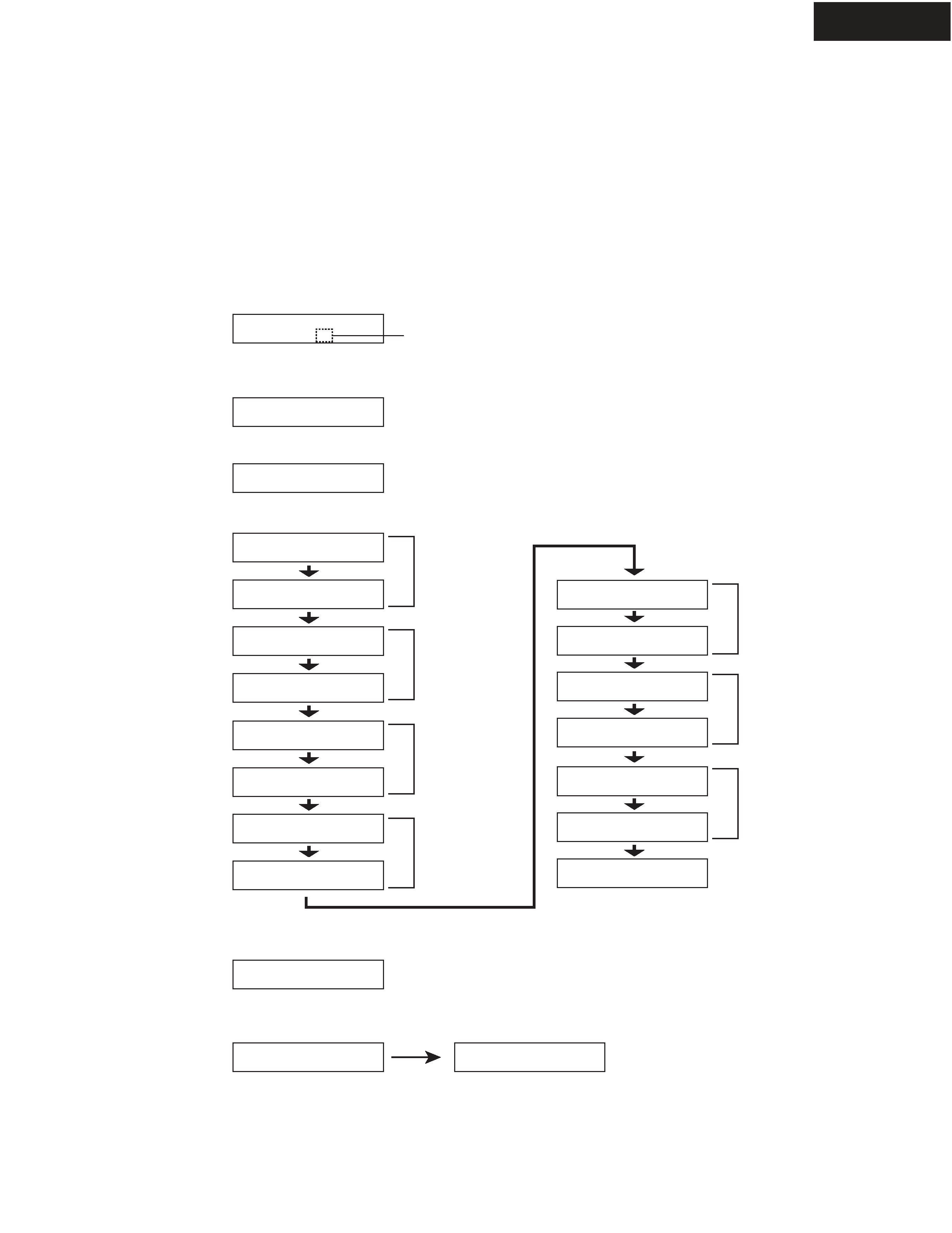
SPEAKER PROTECT-1 (DC VOLTAGE DETECTIION)
1. Press and hold down CD button, then press STANDBY/ON button while the unit is powered on.
" Test - _ " is displayed only for 5 seconds.
2. Press VIDEO 3 button while the characters of " Test - _ " are displayed.
The unit will be in the state of " Test-4-00 ".
3. Repeatedly press +(TONE) button until the characters of " Test-4-21 " are displayed.
[Procedure]
<Note> No load. No input.
Test - _
Test - 4-00
[When]
1. Exchange power transistors (Q6050 - Q6056, Q6060 - Q6066).
2. Exchange amplifier PC board ass'y (NAAF-8779).
Test - 4-21
Check whether the operation starts and continues automatically as follows.
Test - 4-21
Test - 4-22
Test - 4-25
Test - 4-23
Test - 4-24
Protect OK
Protect OK
Protect
Protect OK
Protect OK
Protect OK
Test - 4-35
Clear
Turn off
Front L ch
Check
If all channels are OK, the characters of " Test-4-35 " are displayed.
4. Press STANDBY/ON button.
Front R ch
Check
Center ch
Check
Surround L ch
Check
Surround R ch
Check
Blinks
Test - 4-26
Protect OK
Surround Back L ch
Check
Test - 4-27
Protect OK
Surround Back R ch
Check
HT-R940
OPERATION CHECK-2
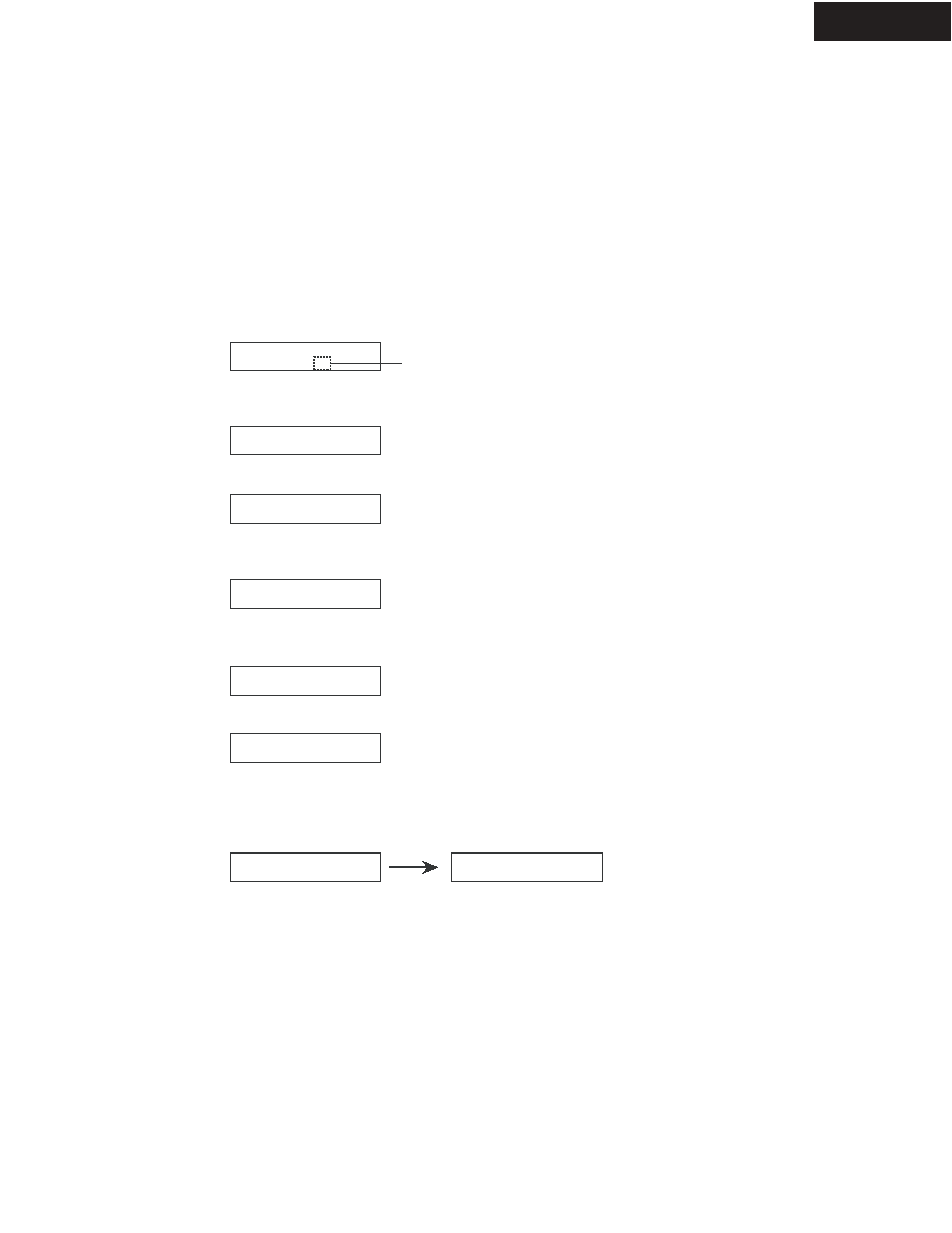
SPEAKER PROTECT-2 (CURRENT DETECTION)
1. Press and hold down CD button, then press STANDBY/ON button while the unit is powered on.
" Test - _ " is displayed only for 5 seconds.
2. Press VIDEO 3 button, while " Test - _ " is displayed.
The unit will be in the state of " Test-4-00 ".
3. Repeatedly press +(TONE) button until " Test-4-35 " is displayed.
4. Connect the dummy load of 3 ohms to the Front L ch speaker terminals.
At this time, confirm that the speaker relay is not turned off.
5. Connect the dummy load of 1 ohm to the Front L ch speaker terminals.
At this time, confirm that the speaker relay is turned off and " Protect " is displayed.
Disconnect the dummy load immediately after checking the display of " Protect ".
6. Check other channels according to the same procedure as 4 and 5.
[Procedure]
<Note> No input.
Do not check two or more channels at the same time.
Do not connect a dummy load to speaker terminal longer than 2 seconds.
Test - _
Test - 4-00
[When]
1. Exchange power transistors (Q6050 - Q6056, Q6060 - Q6066).
2. Exchange amplifier PC board ass'y (NAAF-8779).
Test - 4-35
Clear
Turn off
7. Press the STANDBY/ON button.
Test - 4-35
Protect
Test - 4-35
Blinks
HT-R940
OPERATION CHECK-3
CONTROL OF POWER SUPPLY (OUTPUT SENSOR AND THERMAL SENSOR)
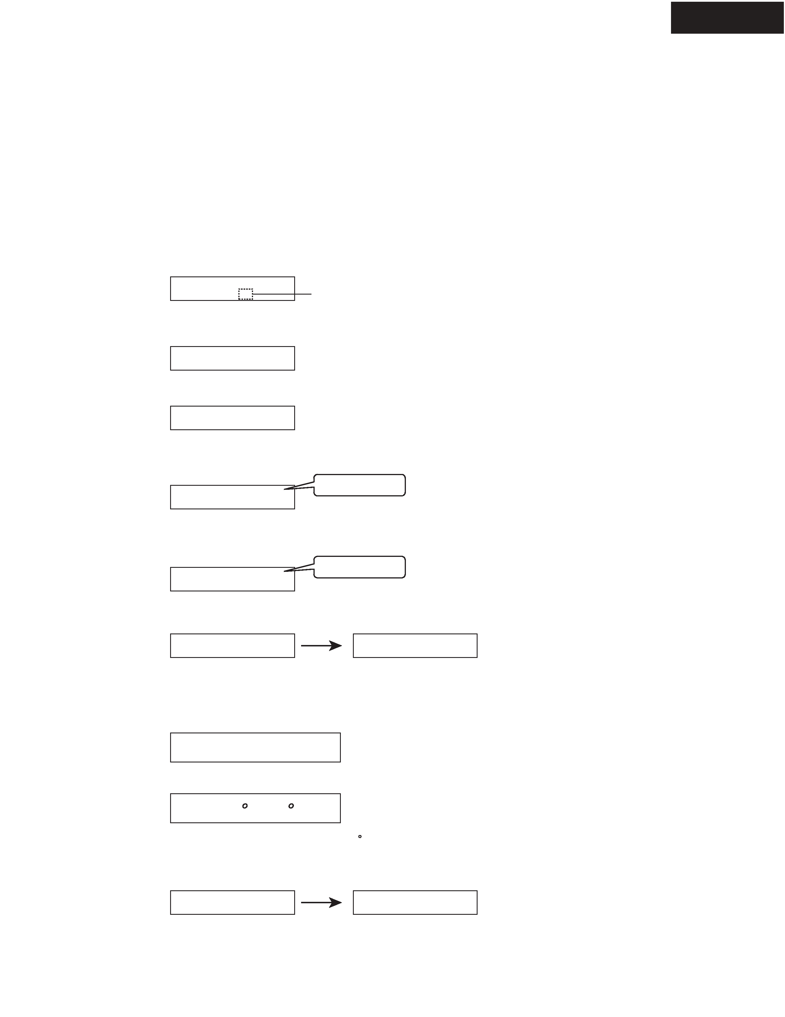
Test - _
Test - 4-00
Test - 4-36
Clear
Turn off
Blinks
Ver. 1.01/06222A
<Ex.>
<Ex.>
T: 25 C/ 77 F
Clear
Turn off
Output sensor
1. Press and hold down CD button, then press STANDBY/ON button while the unit is powered on.
" Test - _ " is displayed only for 5 seconds.
2. Press VIDEO 3 button while " Test - _ " is displayed.
The unit will be in the state of " Test-4-00 ".
3. Repeatedly press +(TONE) button until " Test-4-36 " is displayed.
Test - 4-36
FM STEREO
4. At this time, confirm that the red characters of " FM STEREO " is displayed.
And, confirm that the relays RL6901 and RL6902 are turned off in 2 or 3 seconds.
6. Press STANDBY/ON button.
[Procedure]
<Note> No output. No input.
[When]
1. Exchange power transistors (Q6050 - Q6056, Q6060 - Q6066).
2. Exchange power amplifier PC board ass'y (NAAF-8779).
3. Exchange thermal sensor PC board ass'y (NAETC-8781).
Thermal sensor
1. Press and hold down DISPLAY button, then press STANDBY/ON button when the unit is powered on.
The microprocessor version will be displayed for 3 seconds.
2. Press TONE button while the version is displayed.
4. Press STANDBY/ON button.
Test - 4-37
FM STEREO
5. Press +(TONE) button and confirm that the red characters of " FM STEREO " is displayed.
And, confirm that the relays RL6901 and RL6902 are turned off in 2 or 3 seconds.
3. Confirm that the displayed temperature is within +/-20 C from the ambient temperature.