HT-R820THX
SERVICE MANUAL
SERVICE MANUAL
AV RECEIVER
Black model
MODEL
HT-R820THX
120V AC, 60Hz
BMDC
Ref. No. 3838
102004
RC-571M
STANDBY/ON
PHONES
DISPLAY
TUNING MODE
DIGITAL INPUT
LISTENING
MODE
THX
MEMORY
RETURN
SETUP
VIDEO
2
TAPE
TUNER
C D
VIDEO
3
VIDEO
1
SPEAKERS B
A
MASTER VOLUME
ENTER
S VIDEO
VIDEO
AUDIO
VIDEO
3 INPUT
CLEAR
TUNING
PRESET
HT-R820THX
STANDBY
LR
TONE
VCR
CD
+10
0
CLEAR
12
3
45
6
78
9
V1
V2
V3
DVD
MULTI CH
--/---
TAPE
TUNER
INPUT
I
+
-
ENTER
SET
UP
GUI
DE
RE
TURN
EXIT
Re-EQ
CH SEL
TEST TONE
DSP
DIRECT
STEREO
ALL ST
SURR
L NIGHT
TO
P M
ENU
MEN
U
VOL
+
-
CDR
SAT
AMP
TV
VCR
CABLE
DVD
CD
MD
DISC
CH
TONE
TUNER/
TAPE
DISPLAY
TV
INPUT
PREV
CH
DIMMER
SLEEP
RANDOM
SP A
SP B
MUTING
ANGLE
SEARCH
SUBTITLE
AUDIO
MEMORY
A-B
REPEAT
ON
STANDBY
TV
TV CH
TV VOL
RC-571M
REC
LAST M
REMOTE MODE
OPEN/CLOSE
DSP
THX
VIDEO OFF
OR-EQ
LEVEL
-
LEVEL
+
+
_
SAFETY-RELATED COMPONENT
WARNING!!
COMPONENTS IDENTIFIED BY MARK
ON THE
SCHEMATIC DIAGRAM AND IN THE PARTS LIST ARE
CRITICAL FOR RISK OF FIRE AND ELECTRIC SHOCK.
REPLACE THESE COMPONENTS WITH ONKYO
PARTS WHOSE PART NUMBERS APPEAR AS SHOWN
IN THIS MANUAL.
MAKE LEAKAGE-CURRENT OR RESISTANCE
MEASUREMENTS TO DETERMINE THAT EXPOSED
PARTS ARE ACCEPTABLY INSULATED FROM THE
SUPPLY CIRCUIT BEFORE RETURNING THE
APPLIANCE TO THE CUSTOMER.
HT-R820THX
SPECIFICATIONS
Amplifier Section
Video Section
Tuner Section
General
Audio Outputs
Analog outputs:
Subwoofer pre out:
Speaker outputs:
Phones:
Specifications and features are subject to change without notice.
Power supply:
Power consumption:
Standby power consumption:
Dimensions
(W x H x D):
Weight:
AC 120 V, 60 Hz
6.6 A
2.5 W
17-1/8" x 5-7/8" x 14-13/16"
(435 x 150 x 376 mm)
22.5 lbs. (10.2 kg)
Video Inputs
Component video inputs:
S-Video inputs:
Video inputs:
2 (DVD, Video 1/2/3)
4 (DVD, Video 1-3)
4 (DVD, Video 1-3)
2 (Tape Out, Video 1 Out)
1
6+2
1
4 (Optical 1-3, Coaxial)
6 (CD, Tape, DVD, Video 1-3)
5.1 ch (Front L/R, Center, S
urround L/R, Subwoofer)
Audio Inputs
Digital inputs:
Analog inputs:
Multichannel analog inputs:
1 (Component Video Out)
2 (Video 1 Out, Monitor Out)
2 (Video 1 Out, Monitor Out)
Video Outputs
Component video outputs:
S-Video outputs:
Video outputs:
FM
Tuning frequency range:
Usable sensitivity:
S/N ratio:
THD:
FM stereo separation:
87.5-107.9 MHz
FM STEREO 17.2 dBf, 2.0 µV (75
IHF)
FM MONO 11.2 dBf, 1.0 µV (75
IHF)
FM STEREO 70 dB (IHF-A)
FM MONO 76 dB (IHF-A)
FM STEREO 0.3% (1 kHz)
FM MONO 0.2% (1 kHz)
45 dB at 1 kHz
AM
Tuning frequency range:
Usable sensitivity:
S/N ratio:
THD:
530-1710 kHz
30 µV
40 dB
0.7%
Input sensitivity, output
level and impedance:
Component video
frequency response:
1.0 Vp-p/75
(component and S-Video Y)
0.7 Vp-p/75
(component PB/CB, PR/CR)
0.28 Vp-p/75
(S-Video C)
1.0 Vp-p/75
(composite)
5 Hz-50 MHz
Power output:
All channels:
Dynamic power:
THD (total harmonic
distortion):
Damping factor:
Input sensitivity and
impedance:
Output level and impedance:
Frequency response:
Tone control:
S/N ratio (Direct mode):
Speaker impedance:
130 W (8
, 20 Hz-20 kHz, FTC)
2 x 260 W (3
, front)
2 x 200 W (4
, front)
2 x 150 W (8
, front)
0.08% (rated power)
60 (front, 1 kHz, 8
)
200 mV/47 k
(LINE)
200 mV/470
(REC OUT)
10 Hz-100 kHz/+1 dB,
-3 dB (Direct mode)
±12 dB, 50 Hz (BASS)
±12 dB, 20,000 Hz (TREBLE)
100 dB (CD, IHF-A)
8 ~
SERVICE PROCEDURES
HT-R820THX
1. Replacing the fuses
This symbol located near the fuse indicates that the
fuse used is show operating type, For continued protection against
fire hazard, replace with same type fuse, For fuse rating, refer to
the marking adjacent to the symbol.
Ce symbole indique que le fusible utilise est e lent.
Pour une protection permanente, n'utiliser que des fusibles de meme
type. Ce demier est indique la qu le present symbol est apposre.
3. To initialize the unit
This device employs a microprocessor to perform various
functions and operations. If interference generated by an external
power supply, radio wave, or other electrical sauce results in accident
which causes the specified operations and functions to operate
abnormally.
To perform a result, please follow the procedure below.
1. Press and the hold down the VIDEO 1 button, then press the
STANDBY/ON button when the unit is Power On.
2. After "Clear " is displayed, the preset memory and each mode
stored in the memory, are initialized and will return to the
factory settings.
REF NO.
PART NO.
DESCRIPTION
F6901, F6902
F6901, F6902
F6901 or, F6902 or
F901
F901 or
F903
F903 or
252199
252100
252307
252198
252261
252164
252258
10A-UL
10A-EAK
10A-TL250V
8A-UL
8A-T/UL-ST2
5A-UL/T-237
5A-T/UL-ST2
2. Safety-check out
After correcting the original service problem perform the
following safety check before releasing the set to the customer
Connect the insulating-resistance tester between the plug of
power supply cord and terminal GND on the back panel.
Specifications: More than 10Mohm at 500V
The HT-R820THX uses a battery-less memory backup
system in order to retain radio presets and other settings
when it's unplugged or in the case of a power failure.
Although no batteries are required, the HT-R820THX
must be plugged into an AC outlet in order to charge the
backup system.
Once it has been charged, the HT-R820THX will retain
the settings for several weeks, although this depends on
the environment and will be shorter in humid climates.
5. Memory backup
REMARKS
<Note>
Main microprocessor Q7008 only.
1. Press and the hold down the DISPLAY button , then press the
STANDBY/ON button when the unit is Power ON.
Version is displayed on FL display only for 3 seconds.
2. Press the STANDBY/ON button to Power Off.
4. To check version of microprocessor
Ver. 075 (04809a)
<ex.>
NCDG-8230
25138230B
GND
232RXD
232TXD
NC
FVCC
P7701
Q7008
Main microprocessor
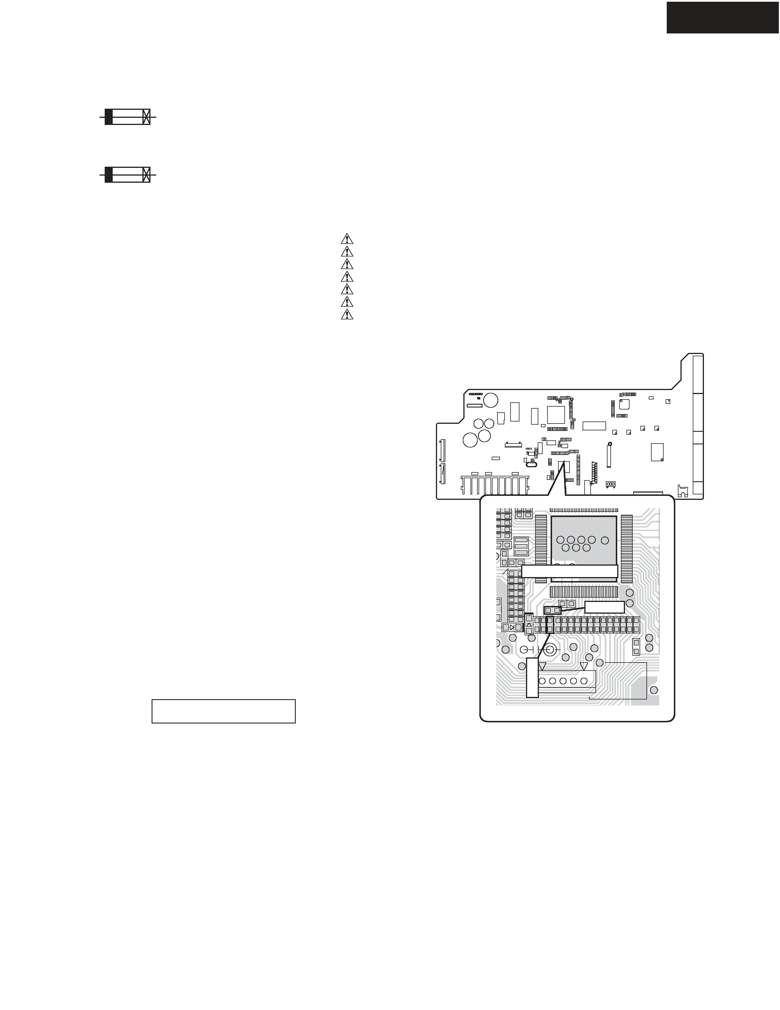
6. Changing the AM band step
1. Necessary to change as follows.
R7003
Change to 10 kohms. Refer to <Fig-1>
R7004
Change to 10 kohms. Refer to <Fig-1>
2. To select.
Press and hold down the TUNER button , then press the
MEMORY button.
Component side
<Fig-1>
NADG-8230 (Pre-amplifier PC board)
R7004
R7003
OPERATION CHECK-1
DC VOLTAGE DETECTION PROTECTORS
HT-R820THX
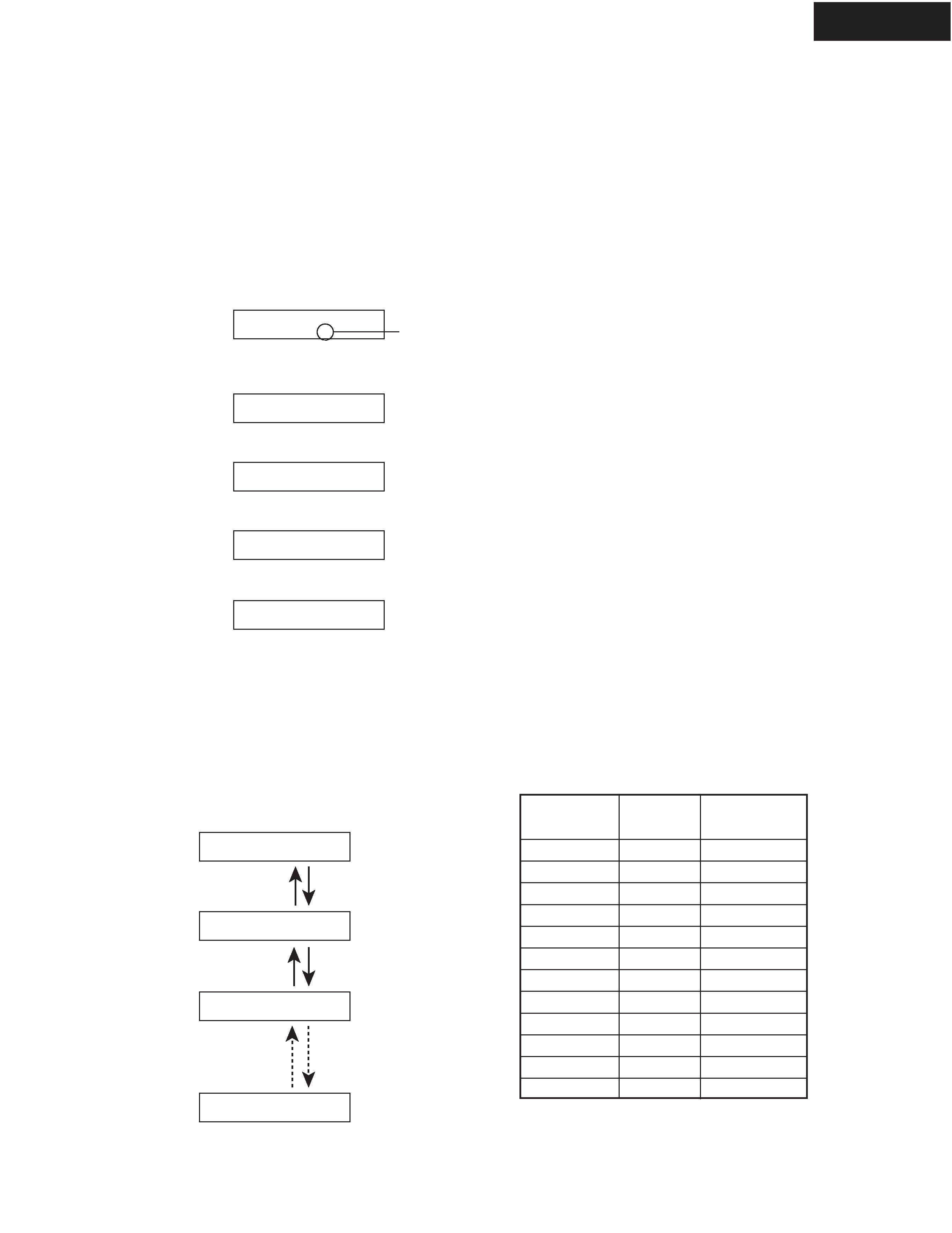
1. Set the unit to test mode " Test-4-00 " .
1-1. Press and the hold down the CD button , then press the STANDBY/ON button when the unit is Power On.
1-2. Press the VIDEO 3 button, while the " Test - _ " is shown.
Unit will be in the state of " Test-4-00 ".
2. Repeat and press SPEAKERS B to the " Test-4-20 " is shown.
3. Check that the " Protect OK " is shown and speaker relays are turn Off.
If a circuit is failure, the " Protect NG " is shown.
4. Check about the " Test 4-21 " to " Test 4-31 " one by one.
Refer to <Fig-1> about the operation method.
5. Press the STANDBY/ON to power Off. (Exit the test mode.)
<Note1>
In test mode " Test 4-20 " to " Test 4-31 ", DC voltage is outputted from DSP IC a pre-amplifier section, and it is inputted into a
power amplifier circuit.
Therefore an external input is unnecessary in check.
<Note2>
Don't connect speakers or any load.
Don't short speaker terminals.
Test - _
Test - 4-00
Test - 4-20
Protect OK
Protect NG
Test - 4-20
Press
" SPEAKER B " button.
Test - 4-21
Press
" SPEAKER B " button.
Test - 4-22
Operation method
Press on " SPEAKER B " button ---> Next step
Press on " SPEAKER A " button ---> Retarn
Test - 4-31
<Fig-1>
Press
" SPEAKER A " button.
Press
" SPEAKER A " button.
Details of TEST MODE 4-20 to 4-31
TEST MODE
4-20
4-21
4-22
4-23
4-24
4-25
4-26
4-27
4-28
4-29
4-30
4-31
DSP
output ch.
FL
FR
C
SL
SR
SB
FL
FR
C
SL
SR
SB
DSP
output voltage
+DC
- DC
+DC
+DC
- DC
+DC
- DC
+DC
- DC
+DC
- DC
+DC
MASTER VOLUME = MAX.
blinks
OPERATION CHECK-2
CURRENT DETECTION PROTECTORS
HT-R820THX
1. Set the unit to test mode " Test-4-00 " .
1-1. Press and the hold down the CD button , then press the STANDBY/ON button when the unit is Power On.
1-2. Press the VIDEO 3 button, while the " Test - _ " is shown.
Unit will be in the state of " Test-4-00 ".
2. Repeat and press SPEAKERS B to the " Test-4-32 " is shown.
3. Connect the road resistor 3 ohms to the speaker terminal.
4. Check that the " Protect " is not shown.
5. Connect the road resistor 1.5 ohms to the speaker terminal.
6. Check that the " Protect " is shown, and speaker relays are turn off.
7. Check about the FL, FR, C, SL, SR and SB channel one by one.
8. Press the STANDBY/ON to power Off. (Exit the test mode)
<Note1>
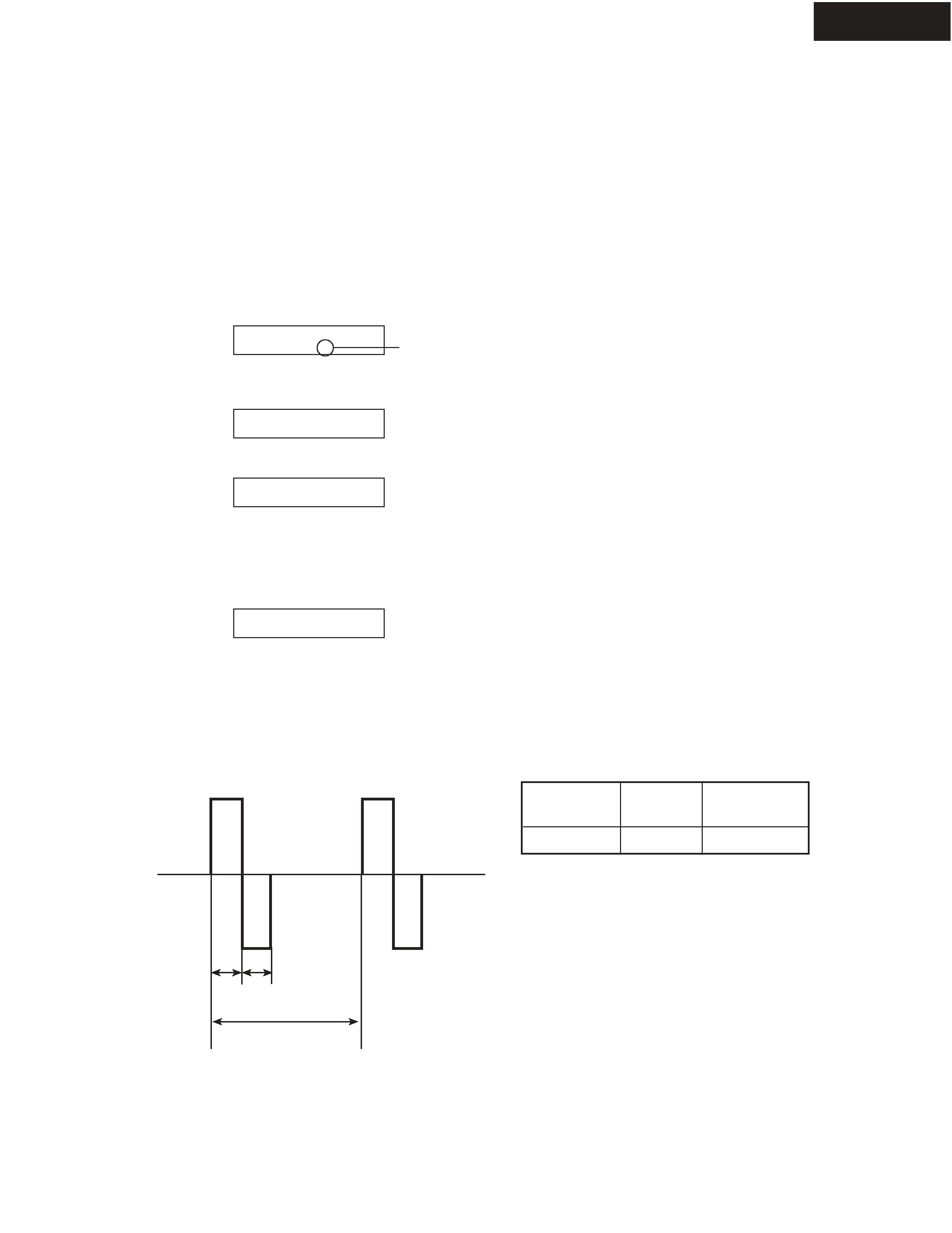
In test mode " Test 4-32 ", the pulse waveform is outputted from DSP IC on the pre-amplifier section, and it is inputted into
a power amplifier circuit. Refer to <Fig-1>.
Therefore an external input is unnecessary in check.
<Note2>
Don't connect speakers or any load.
Don't short speaker terminals.
Don't check two or more channels simultaneously.
Test - _
Test - 4-00
Test - 4-32
Protect
The output waveform from DSP IC in the test mode 4-32.
<Fig-1>
Details of TEST MODE 4-32
TEST MODE
4-32
DSP
output ch.
ALL
DSP
output voltage
Max.
MASTER VOLUME = 54
2 ms 2 ms
20 ms
blinks