HT-R430
SERVICE MANUAL
SERVICE MANUAL
Black and Silver models
Ref. No. 3866
052005
AV RECEIVER
120V AC, 60Hz
S MDD
230-240V AC, 50Hz
S MPA
MODEL
HT-R430
120V AC, 60Hz
B MDD
230-240V AC, 50Hz
B MPA
TONE
+
STEREO
LISTENING MODE
DISPLAY DIGITAL INPUT
DIMMER
MEMORY TUNING MODE
RETURN
TUNING / PRESET
ENTER
SETUP
STANDBY
STANDBY/ON
CLEAR
PHONES
MULTl CH
DVD
VIDEO 1/VCR
VIDEO 2
VIDEO 3
TAPE
TUNER
CD
MASTER VOLUME
A SPEAKERS B
RC-606S
MUTING
MENU
TOP MENU
SP A / B
SETUP
RETURN
RANDOM
SUBTITLE
PLAY MODE
AUDIO
REPEAT
RC-
606S
--/---
TAPE/AMP
ON
STANDBY
DIMMER
SLEEP
INPUT SELECTOR
REMOTE MODE
V
1
V
2
V
3
CD
TAPE
TUNER
DVD
MULTI CH
LISTENING MODE
DISPLAY
TEST TONE
CH SEL
SURROUND
STEREO
CINE FLTR
LEVEL+
LEVEL-
L NIGHT
OR-EQ
VOL
CDR
MD
DVD
RECEIVER
CD
+10
0
CLR
12
3
45
6
789
ENTER
CH
DISC
SAFETY-RELATED COMPONENT
WARNING!!
COMPONENTS IDENTIFIED BY MARK
ON THE
SCHEMATIC DIAGRAM AND IN THE PARTS LIST ARE
CRITICAL FOR RISK OF FIRE AND ELECTRIC SHOCK.
REPLACE THESE COMPONENTS WITH ONKYO
PARTS WHOSE PART NUMBERS APPEAR AS SHOWN
IN THIS MANUAL.
MAKE LEAKAGE-CURRENT OR RESISTANCE
MEASUREMENTS TO DETERMINE THAT EXPOSED
PARTS ARE ACCEPTABLY INSULATED FROM THE
SUPPLY CIRCUIT BEFORE RETURNING THE
APPLIANCE TO THE CUSTOMER.
HT-R430
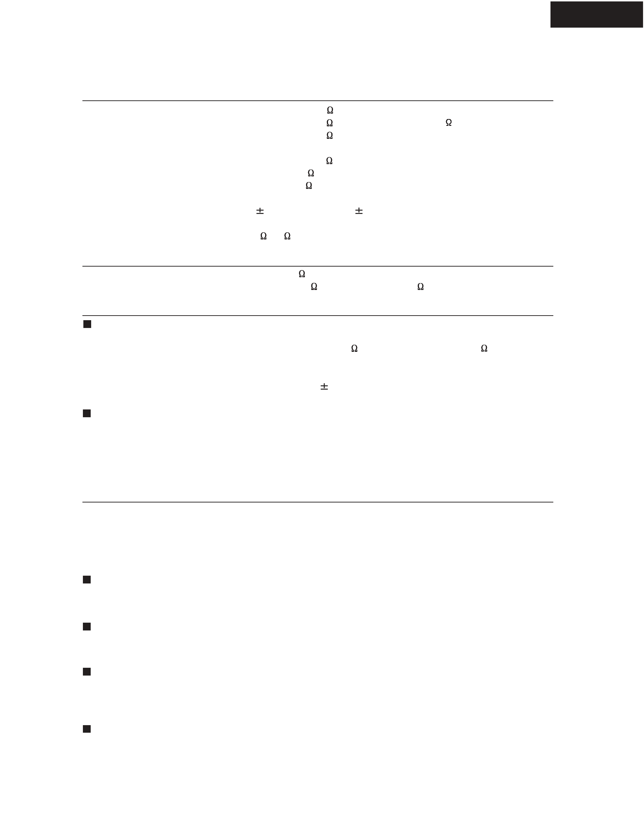
SPECIFICATIONS
Power Output 2 channel driven:
Dynamic Power
THD (Total Harmonic Distortion)
Damping Factor
Input Sensitivity and Impedance
Output Level and Impedance
Frequency Response
Tone Control
Signal to Noise Ratio
Speaker Impedance
100 W + 100 W (8
, 1kHz, FTC)
210 W + 210 W (3
, Front) / 155 W + 155 W (4
, Front) /
105 W + 105 W (8
, Front)
0.08% (Power Rated)
60 (Front, 1kHz, 8
)
200 mV/ 47 k
(LINE)
200 mV/ 470
(REC OUT)
10 Hz 100 kHz / +1 dB -3 dB (Direct mode)
10 dB, 50 Hz (BASS) /
10 dB, 20 kHz (TREBLE)
100 dB (LINE, IHF-A)
8
16
Input Sensitivity/Output
Level and Impedance
1 Vp-p / 75
(Component and S-Video Y)
0.28 Vp-p / 75
(S-Video C) / 1 Vp-p / 75
(Composite)
Tuning Frequency Range
Usable Sensitivity
Signal to Noise Ratio
THD
Frequency Response
Stereo Separation
North American: 87.5 MHz 107.9 MHz / Others: 87.5 MHz 108.0 MHz
Stereo: 17.2 dBf 2 µV(75
IHF) / Mono: 11.2 dBf 1 µV(75
IHF)
Stereo: 70 dB (IHF-A) / Mono: 76 dB (IHF-A)
Stereo: 0.3% (1kHz) / Mono: 0.2% (1kHz)
30 Hz 15 kHz /
1 dB
45 dB (1kHz)
Tuning Frequency Range
Usable Sensitivity
Signal to Noise Ratio
THD
North American: 530 kHz 1710 kHz /
Others: 522 kHz 1611 kHz 530 kHz 1710 kHz
30 µV
40 dB
0.70%
Power Supply
Power Consumption
Stand-by Power Consumption
Dimensions (W x H x D)
Weight
North American: AC 120 V, 60 Hz / Australian: AC 230 240 V, 50 Hz /
North American: 5.5 A / Others: 380 W
North American: 0.1 W / Others: 0.5 W
17-1/8" x 5-7/8" x 14-1/2", 345 x 150 x 369 mm
North American: 19.6 lbs. (8.9 kg) / Others: 21.2 lbs. (9.6 kg)
S-Video
Composite
DVD, VIDEO1, VIDEO2
DVD, VIDEO1, VIDEO2, VIDEO3
S-Video
Composite
MONITOR, VIDEO1
MONITOR, VIDEO1
Digital Inputs
Analog Inputs
Multichannel Inputs
Optical: 1 / Coaxial: 1
DVD(MULTI CHANNEL), VIDEO1, VIDEO2, VIDEO3, TAPE, CD
6
Analog Outputs
Subwoofer Pre Outputs
Speaker Outputs
Phones
TAPE, VIDEO1
1
SP-A (L, R, C, SL, SR, SB) + SP-B (L, R)
1
Amplifier section
Video section
Tuner section
General
Video inputs
Video outputs
Audio inputs
Audio outputs
FM
AM
SERVICE PROCEDURE
HT-R430
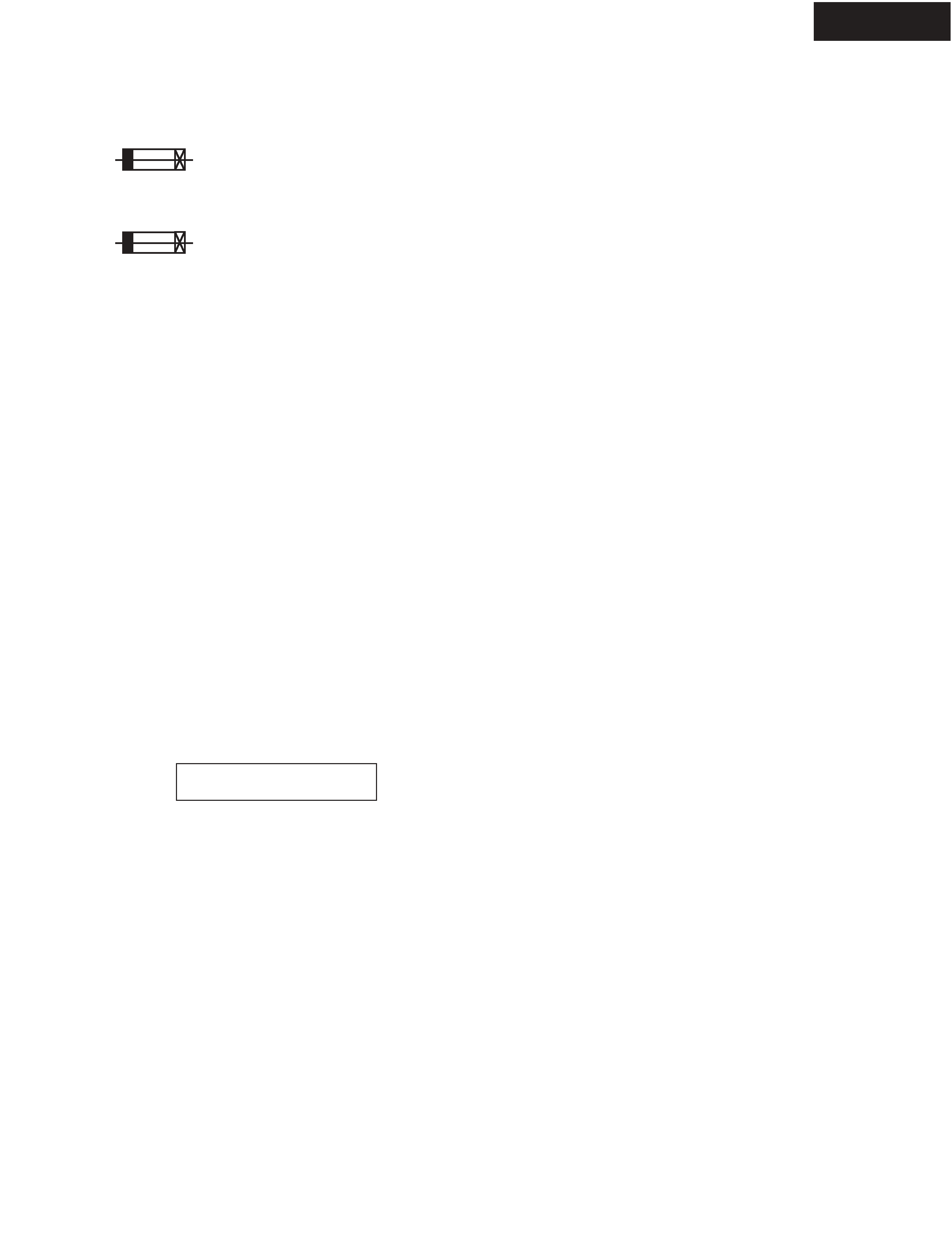
1. Replacing the fuses
This symbol located near the fuse indicates that the
fuse used is show operating type, For continued protection against
fire hazard, replace with same type fuse, For fuse rating, refer to
the marking adjacent to the symbol.
Ce symbole indique que le fusible utilise est e lent.
Pour une protection permanente, n'utiliser que des fusibles de meme
type. Ce demier est indique la qu le present symbol est apposre.
2. To initialize the unit
The AV receiver uses a battery-less memory backup system in order to retain radio presets and other settings
when it's unplugged or in the case of a power failure.
Although no batteries are required, the AV receiver must be plugged into an AC outlet in order to charge the
backup system. Once it has been charged, the AV receiver will retain the settings for several weeks,
although this depends on the environment and will be shorter in humid climates.
1. Press and the hold down the VIDEO 1/VCR button, then press the STANDBY/ON button when the unit is Power on.
2. After " Clear " is displayed, the preset memory and each mode stored in the memory, are initialized and will return to
the factory settings.
4. Memory Backup
<Note>
Main microprocessor Q701 only.
1. Press and the hold down the DISPLAY button, then press the STANDBY/ON button when the unit is Power on.
Version is displayed on FL display only for 3 seconds.
2. Press the STANDBY/ON button to Power off.
3. To check version of microprocessor?
Ver.1.01/05305a
Ex.
REF NO.
F901
F901 or
F902
F902 or
F902 or
F903
F903 or
F903
F903 or
F903 or
F6901
F6901 or
F6902
F6902 or
DESCRIPTION
6.3A-UL/T-237
6.3A-T/UL-ST2
3.15A-SE-EAK FUSE
3.15A-SE-TL250V
3.15A-SE-TL250V
5A-UL/T-237
5A-T/UL-ST2
2.5A-SE-EAK FUSE
2.5A-SE-TL250V
2.5A-SE-TL250V
8A-UL
8A-T/UL-ST2
8A-UL
8A-T/UL-ST2
PART NO.
252166
252260
252076
252242
252276
252164
252258
252075
252241
252275
252198
252261
252198
252261
REMARKS
!, <DD>
!, <DD>
!, <PA>
!, <PA>
!, <PA>
!, <DD>
!, <DD>
!, <PA>
!, <PA>
!, <PA>
!
!
!
!
PART NAME
FUSE
FUSE
FUSE
FUSE
FUSE
FUSE
FUSE
FUSE
FUSE
FUSE
FUSE
FUSE
FUSE
FUSE
<Notes>
<DD>: USA model only
<PA>: Australian model only
HT-R430
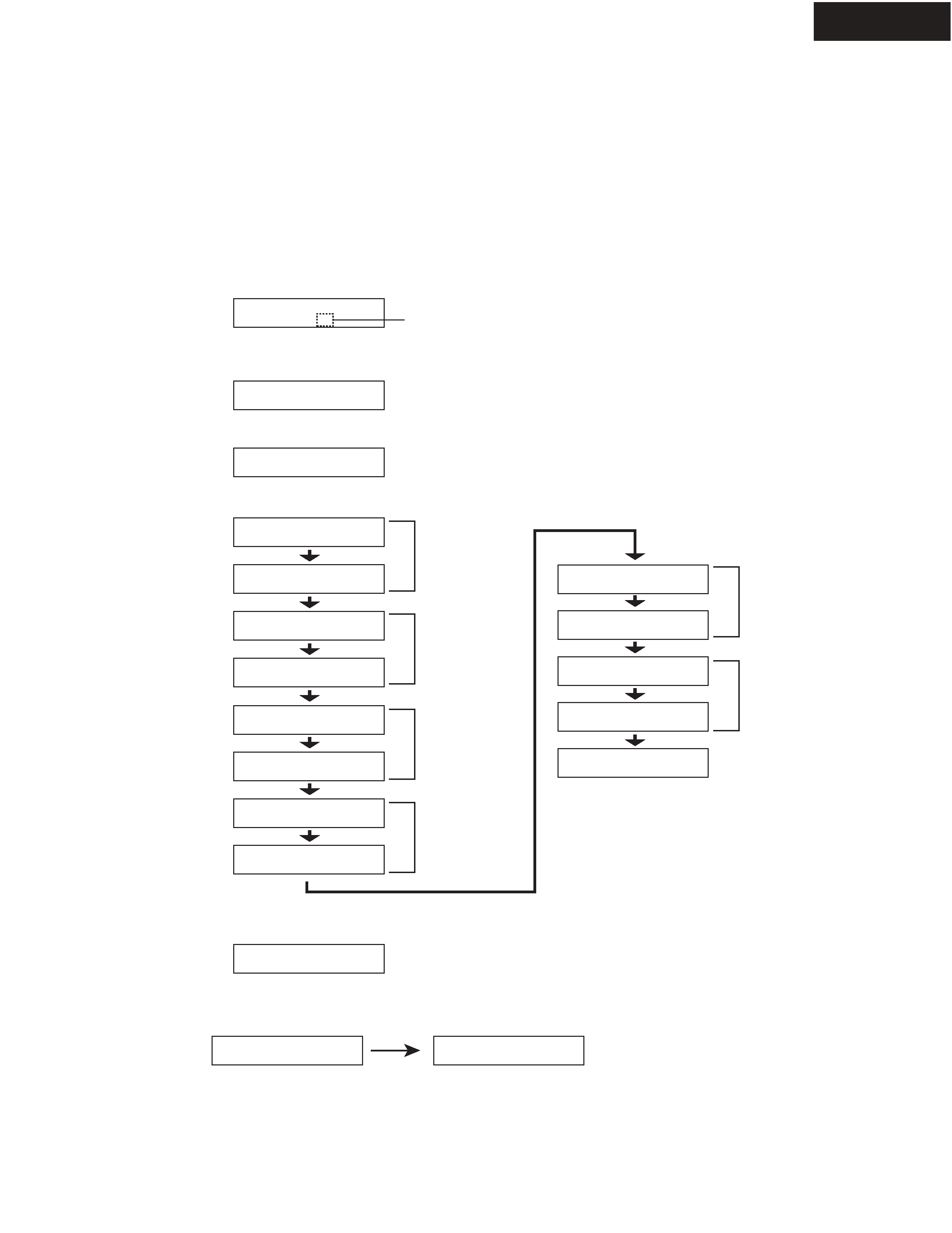
OPERATION CHECK-1
SPEAKER PROTECT-1 (DC VOLTAGE DETECTION)
1. Press and the hold down the CD button, then press the STANDBY/ON button when the unit is Power ON.
" Test - _ " is displays it only for 5 seconds.
2. Press the VIDEO 3 button, while the character of " Test - _ " is displayed.
Unit will be in the state of " Test-4-00 ".
3. Repeatedly press TONE
+ button until the character of " Test-4-21 " is displayed.
[Procedure]
<Note>
No load. No input.
Test - _
Test - 4-00
[When]
1. Exchange power transistors (Q6050 - Q6065).
2. Exchange amplifier PC board ass'y (NAAF-8523).
Test - 4-21
Checking the operation starts automatically as follows.
Test - 4-21
Test - 4-22
Test - 4-25
Test - 4-23
Test - 4-24
Protect OK
Protect OK
Protect
Protect OK
Protect OK
Protect OK
Test - 4-35
Clear
Turn off
Front L ch
Check
If all channel are OK, the character of " Test - 4 - 35 " is displayed.
4. Press the STANDBY/ON button.
Front R ch
Check
Center ch
Check
Surround L ch
Check
Surround R ch
Check
Blinks
Test - 4-26
Protect OK
Surround Back ch
Check
HT-R430
OPERATION CHECK-2
SPEAKER PROTECT-2 (CURRENT DETECTION)
1. Press and the hold down the CD button, then press the STANDBY/ON button when the unit is Power ON.
" Test - _ " is displays it only for 5 seconds.
2. Press the VIDEO 3 button, while the character of " Test - _ " is displayed.
Unit will be in the state of " Test-4-00 ".
3. Repeatedly press TONE
+ button until the character of " Test-4-35 " is displayed.
4. Connect the Dummy load of 3 ohms to the Front Lch speakers terminal.
At this time, check the speaker relay is not turned off.
5. Connect the dummy load of 1 ohm to the Front Lch speakers terminal.
At that time, you check the speaker relay is turned off and " Protect " is displayed.
Disconnect the dummy load at once when check the display of " Protect ".
6. Check other channels according to the same procedure.
[Procedure]
<Note>
No input.
Do not check two or more channels at the same time.
Do not connect dummy load to speaker terminals for seconds 2 or more.
Test - _
Test - 4-00
[When]
1. Exchange power transistors (Q6050 - Q6065).
2. Exchange amplifier PC board ass'y (NAAF-8523).
Test - 4-35
Clear
Turn off
7. Press the STANDBY/ON button.
Test - 4-35
Protect
Test - 4-35
Blinks