FR-N3X
SERVICE MANUAL
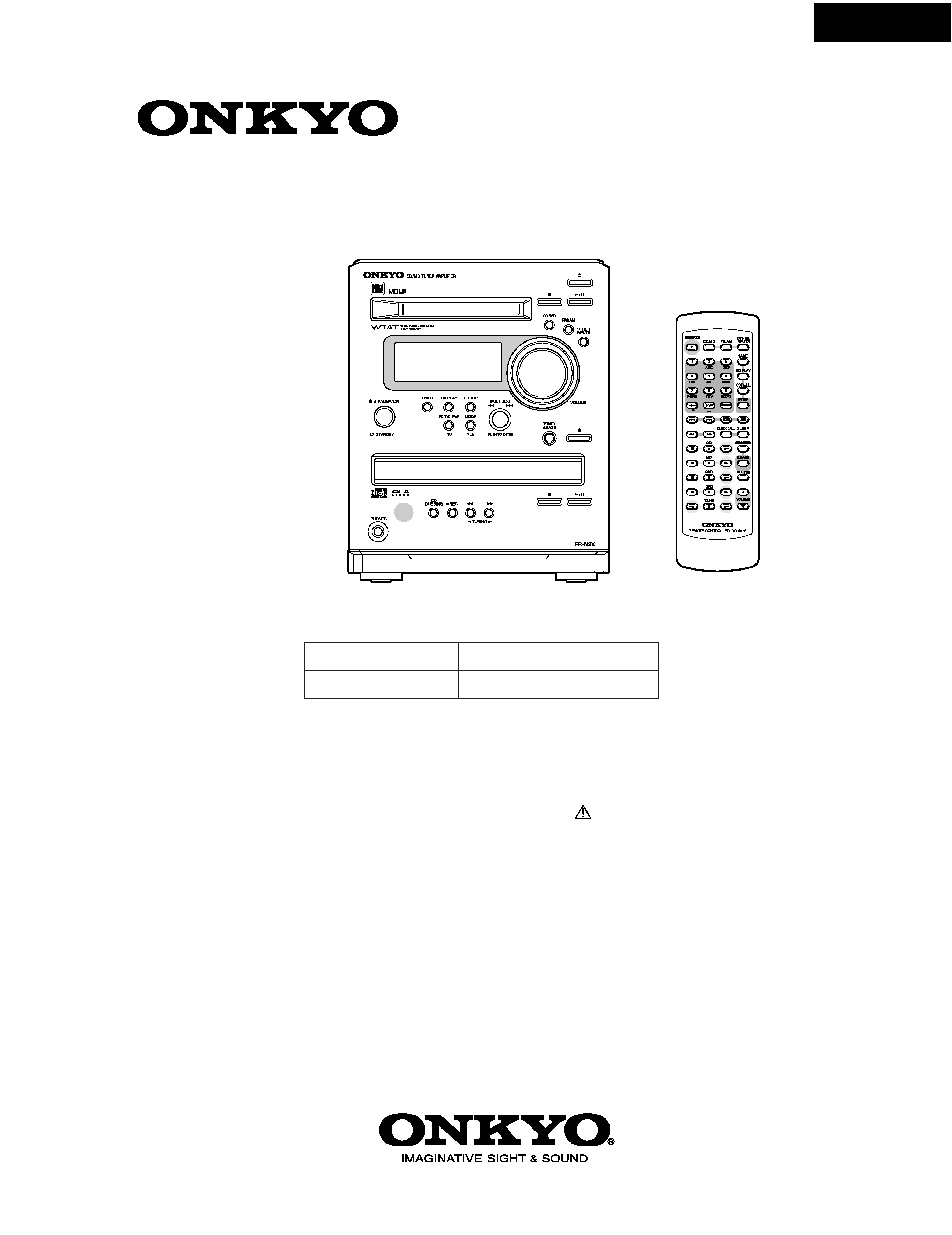
CD/MD TUNER AMPLIFIER
Silver model
MODEL FR-N3X
Ref. No. 3738
062002
120V AC, 60Hz
220-230V AC, 50/60Hz
UDT
UGQ,UGR,UGT
RC-497S
SAFETY-RELATED COMPONENT
WARNING!!
COMPONENTS IDENTIFIED BY MARK
ON THE
SCHEMATIC DIAGRAM AND IN THE PARTS LIST ARE
CRITICAL FOR RISK OF FIRE AND ELECTRIC SHOCK.
REPLACE THESE COMPONENTS WITH ONKYO
PARTS WHOSE PART NUMBERS APPEAR AS SHOWN
IN THIS MANUAL.
MAKE LEAKAGE-CURRENT OR RESISTANCE
MEASUREMENTS TO DETERMINE THAT EXPOSED
PARTS ARE ACCEPTABLY INSULATED FROM THE
SUPPLY CIRCUIT BEFORE RETURNING THE
APPLIANCE TO THE CUSTOMER.
FR-N3X
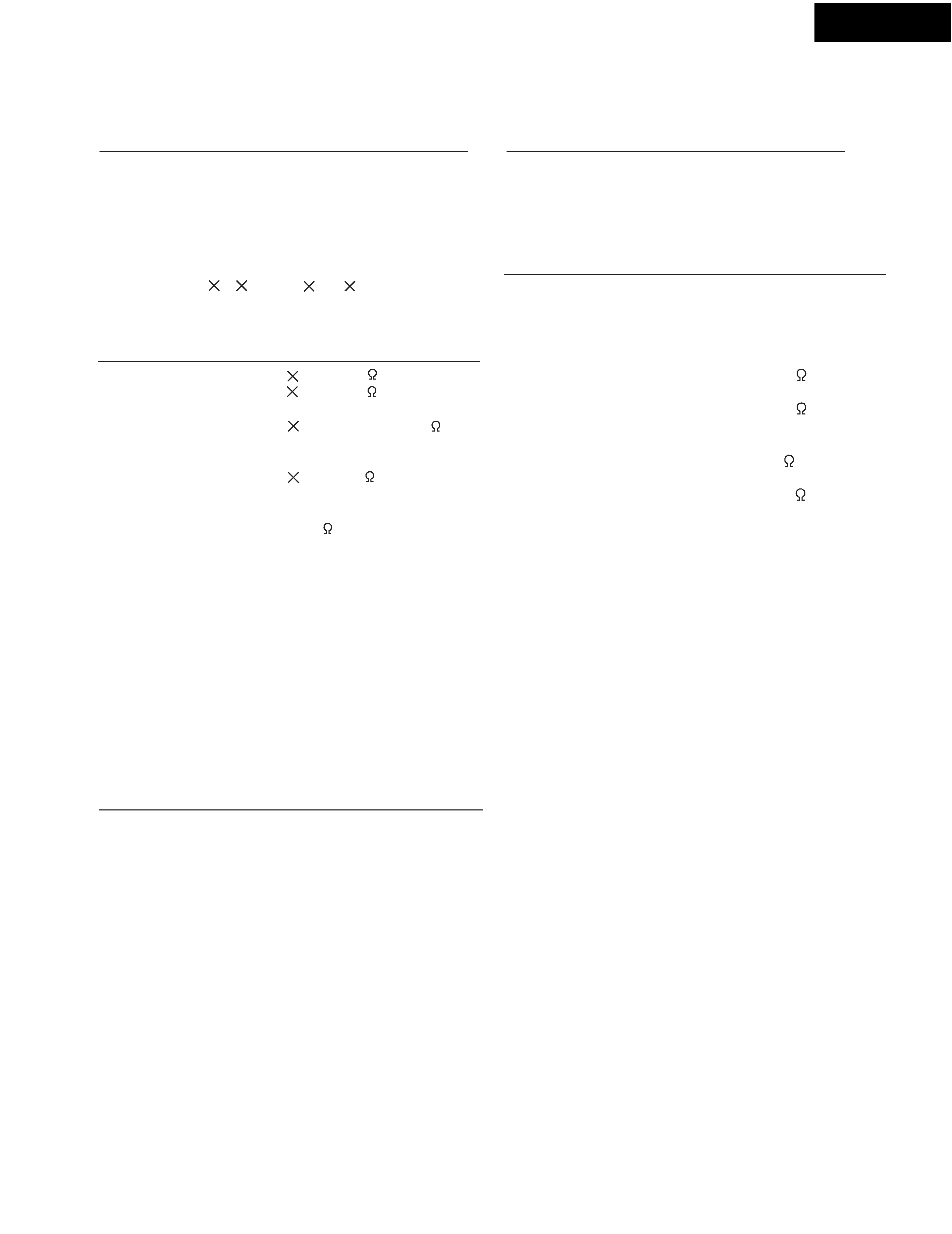
SPECIFICATIONS
General
Power supply
AC 220-230 V, 50/60 Hz
AC 120 V, 60 Hz
Power consumption
46 W (220-230 V, 50/60 Hz)
55 W (120 V, 60 Hz)
(Standby)
1.5 W
Clock precision
monthly error: +/- 30 seconds
(at 25 degrees Celsius)
Dimensions (W
H
D) 155
190
361 mm
Weight
4.7 kg
Amplifier
Power output
2
18 W at 4
EIAJ
2
15 W at 6
EIAJ
Rated Power
2
13W min, RMS at 4
1 kHz no more than
0.4 % THD
Dynamic power
2
14 W at 4
Total harmonic distortion 0.4 % at rated power
IM distortion
0.4 % at rated power
Damping factor
25 at 8
Sensitivity and impedance
LINE, CDR/TAPE:
300 mV, 50 k
CDR/TAPE:
300 mV, 50 k
Frequency response
10 to 100,000 Hz : +3.5, -3dB
Tone control
S.BASS +10 dB at 50 Hz
Bass
120 Hz
7 positions (-7, -5, -2.5, 0, +2.5, +5, +7 dB)
10 kHz
Signal to noise ratio
LINE, CDR/TAPE: 100dB
(IHF-A)
Muting
50 dB
CD player
Signal readout system
Optical non-contact
Frequency response
10 Hz to 20 kHz (± 2 dB)
Below threshold of
measurability
MD recorder
Signal readout system
Optical non-contact
Frequency response
10 Hz to 20 kHz (± 2 dB)
Wow and flutter
Below threshold of
measurability
Tuner
Tuning range
FM: 87.50 to 108.00 MHz
(50 kHz steps)
AM: 522 to 1611 kHz
(9 kHz steps)
Usable sensitivity
FM
Mono:11.2 dBf,
1.0 µV (75
IHF)
Stereo:17.2 dBf,
2.0 µV (75
IHF)
AM: 30 µV
50 dB quieting sensitivity
FM
Mono:17.2 dBf,
2.0µV (75
)
Stereo:37.2 dBf,
20.0 µV (75
)
Capture ratio
2.0 dB
Image rejection ratio
FM: 85 dB
AM: 40 dB
IF rejection ratio
FM: 90 dB
AM: 40 dB
Signal to noise ratio
FM
Mono : 72 dB IHF
Stereo : 67 dB IHF
AM: 40 dB
Selectivity
FM: 50 dB
(±300 kHz at 40 kHz devi.)
Harmonic distortion
FM: Mono: 1.0 %
Stereo: 0.3 %
AM: 0.7 %
Frequency response
FM: 30 to 15,000 Hz (±1.5 dB)
Stereo separation
FM: 45 dB at 1,000 Hz
FM: 30 dB at 100 to 10,000 Hz
Trable
Wow and flutter
7 positions (-7, -5, -2.5, 0, +2.5, +5, +7 dB)
Specifications and features are subject to change without notice.
FR-N3X
FR-N3X
A082
A082
A082
A079
A073
A082
A109
Z001
Z003
Z002
Z004
A049
A067
P351
A070
A040
A052
A001
A097
A098
A100
A103
A089
A090
A099
A106
A040
Q559
Q557
Q558 Q560
U7
U1
A040
A040
A037
U9
P901
A034
A040
A067
A022
U4
U8
A101
A042
A040
U10
P102
U6
A016
F901
T901
A031
A019
A106
P451
A058
P201
P202
A085
A041
A041
A043
A107
U5
U3
U2
A040
A019
P101
U11
A013
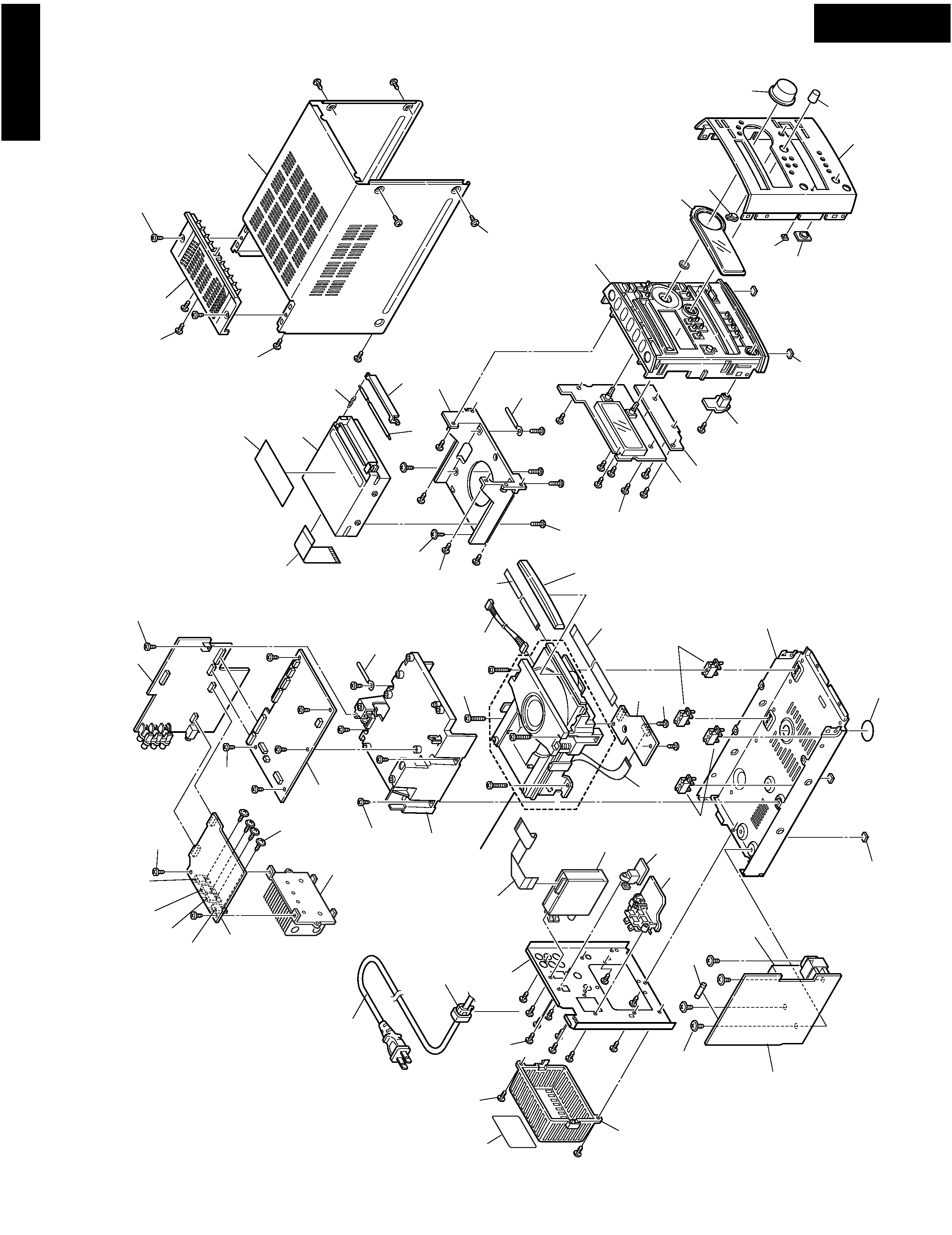
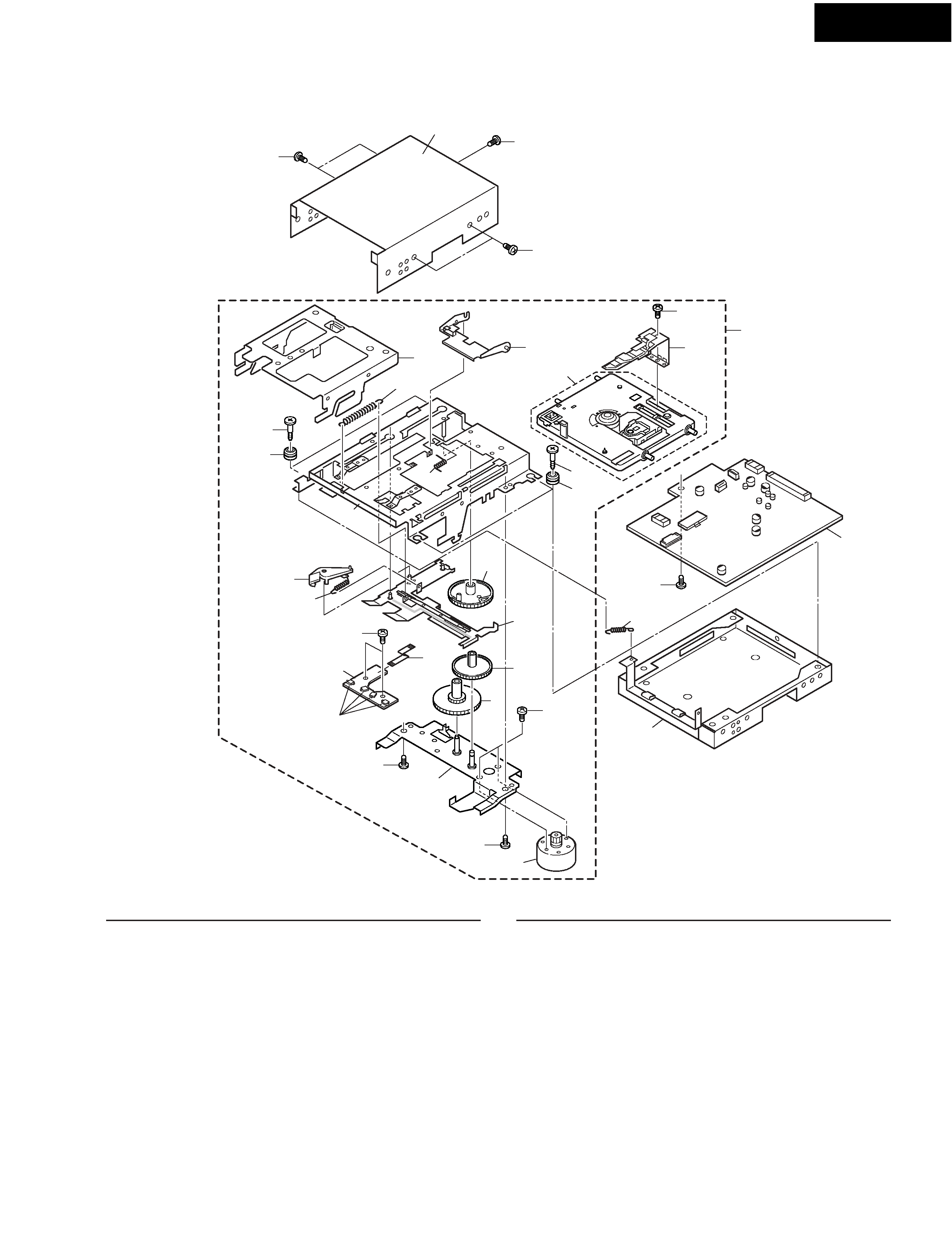
EXPLODED VIEW
Refer to "EXPLODED VIEWS
OF CD MECHANISM"
FR-N3X
PROTECTION OF EYES FROM LASER BEAM DURING SERVICING
This set employs a laser. Therefore, be sure to follow carefully
the instructions below when servicing.
WARNING!!
SERVICE WARNING : DO NOT APPROACH THE
LASER EXIT WITH THE EYE TOO CLOSELY.
IN CASE IT IS NECESSARY TO CONFIRM LASER
BEAM EMISSION, BE SURE TO OBSERVE FROM
A DISTANCE OF MORE THAN 30cm FROM THE
SURFACE OF THE OBJECTIVE LENS ON THE
OPTICAL PICK-UP BLOCK.
Laser Diode Properties
Material: GaAS/GaALAs
Wavelength: 780nm
Emission Duration: continuous
Laser output: max. 0.5mW*
*This output is the value measured at a distance about 1.8mm
from the objective lens surface on the Optical Pick-up Block.
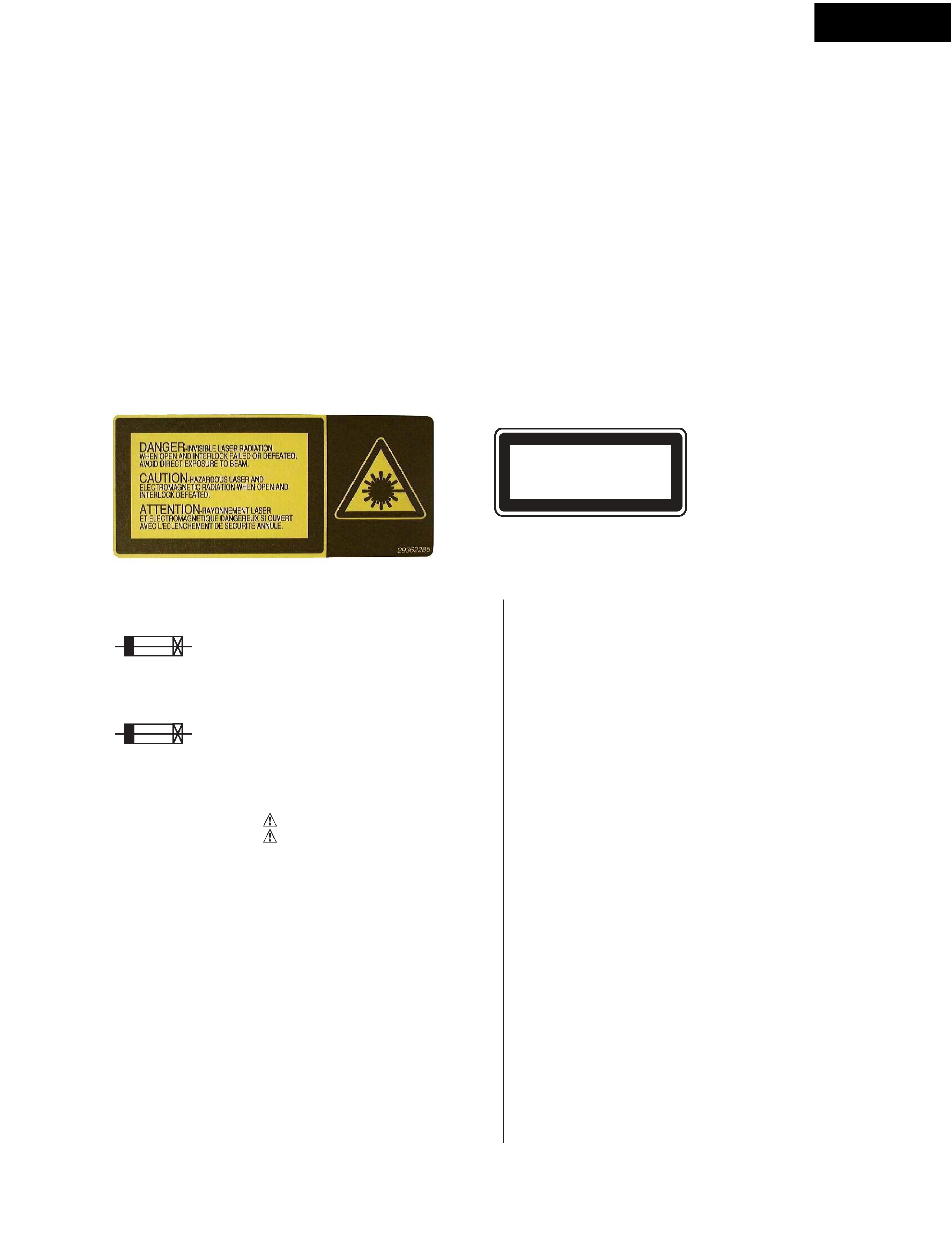
LASER WARNING LABEL
The label shown below are affixed.
1. Warning label
2. Class 1 label
"CLASS 1 LASER
PRODUCT"
LUOKAN 1
LASERLAITE
KLASS 1
LASER APPARAT
SERVICE PROCEDURE
1. Replacing the fuses
REF.NO. PART NO.
DESCRIPTION
F901A
252158
1.6A-UL/T-237, Fuse <DT>
252083
0.4A-SE-EAK, Fuse <GT,GR,GQ>
NOTE : <DT>
: 120 V model only
<GT,GR,GQ>
: 220 - 230 V models only
This symbol located near the fuse indicates that the
fuse used is show operating type, For continued protection against
fire hazard, replace with same type fuse , For fuse rating, refer to
the marking adjest to the symbol.
(1) Press and the hold down the CD STOP button , then press the
STANDBY/ON button.
(2) All segment light up and character scroll, the preset memory
and each mode stored in the memory, are initialized and will
return to the factory settings.
(3) Press the STANDBY/ON button.
(4) Disconnect the AC power supply cord from a wall outlet.
2. How to initialize the unit
Ce symbole indique que le fusible utilise est e lent.
Pour une protection permanente, n'utiliser que des fusibles de meme
type. Ce demier est indique la qu le present symbol est apposre.
SERVICE PROCEDURES
5. Change the band step
R703
R704
R705
R706
R707
R708
NC
10k
NC
10k
NC
10k
10k
NC
NC
10k
NC
10k
9kHz
10kHz
AM Band step
NC:No connection
3. How to check version of MD mechanism
microprocessor?
(1) Connect the AC power supply cord to a wall outlet.
(2) Press STANDBY/ON to turn on the unit.
(3) Press CD/MD to select the "MD " position, and
Change into the state of "No Disc ".
(4) Press MODE/YES as pressing down DISPLAY.
Microprocessor version on the Fl display
Ex.
"020328 EXX-a"
(5) Disconnect the AC power supply cord from a wall outlet.
4. How to check version of Main microprocessor(Q701)
and Sub microprocessor(Q801)?
(1) Connect the AC power supply cord to a wall outlet.
Pushing STANDBY/ON is continued at operation of (2) and (3).
(2) Press STANDBY/ON as pressing down MULTI JOG.
Main-microprocessor version on the Fl display
Ex.
"Main 020327A "
(3) Press STANDBY/ON as pressing down MULTI JOG.
Sub-microprocessor version on the Fl display
Ex.
"Sub 020227A "
(4) Disconnect the AC power supply cord from a wall outlet.
FR-N3X
34
35
35
35
14
16
15
20
21
23
24
18
7
31
6
5
26
27
33
13
13
11
11
10
9
2
2
1
8
30
17
4
3
SW1--SW4
32
PART NO.
DESCRIPTION
---
7685-791-01
---
1792-100-31
2646-555-02
2646-554-01
X2646-726-1
2646-563-01
2646-556-01
---
2646-548-01
2647-337-01
---
2646-559-02
2646-562-01
Motor Plate ass'y
Screw +PTT2.6 x 5 (S)
L-SW Mount 2
Flexible flat cable (5 core)
Gear (Relay B)
Gear (Relay A)
Frame ass'y, slot
Spring (Slot arm), Tension coil
Slot Arm
Frame ass'y, Road
Insulator
Screw, Step
Frame, Slide
Arm, head
Spring, Tension coil
1
2
3
4
5
6
7
8
9
10
11
13
14
15
16
REF NO.
PARTS LIST
The mechanical parts with no part number
in the exploded views are not supplied.
EXPLODED VIEW OF MECHANISM (MD) -1
MD MECHANISM : KMK-260EEO
PART NO.
DESCRIPTION
17
18
20
21
23
24
26
27
30
31
32
33
34
35
REF NO.
2646-561-01
2646-560-02
2627-529-01
8620-021-71
---
7685-791-09
2646-545-01
---
X2626-328-1
7627-852-38
7685-780-01
---
---
7621-259-25
Spring, SP Tension
Cam, Mode
Grip (+P1.7 x 2.5 Type2)
MD Over write head
MD mount PC board
Screw +PTT2.6 x 5 (S)
Spring (Door arm), Tension coil
Case (Lower)
Loading motor ass'y
Precision screw (+P1.7 x 1.8 Type 3)
Screw +PTT2 x 3 (S)
Loading ass'y
Case (Upper)
Screw (+P2.6 x 4)
Refer
to
"EXPLODED
VIEWS
OF
MECHANISM-2"