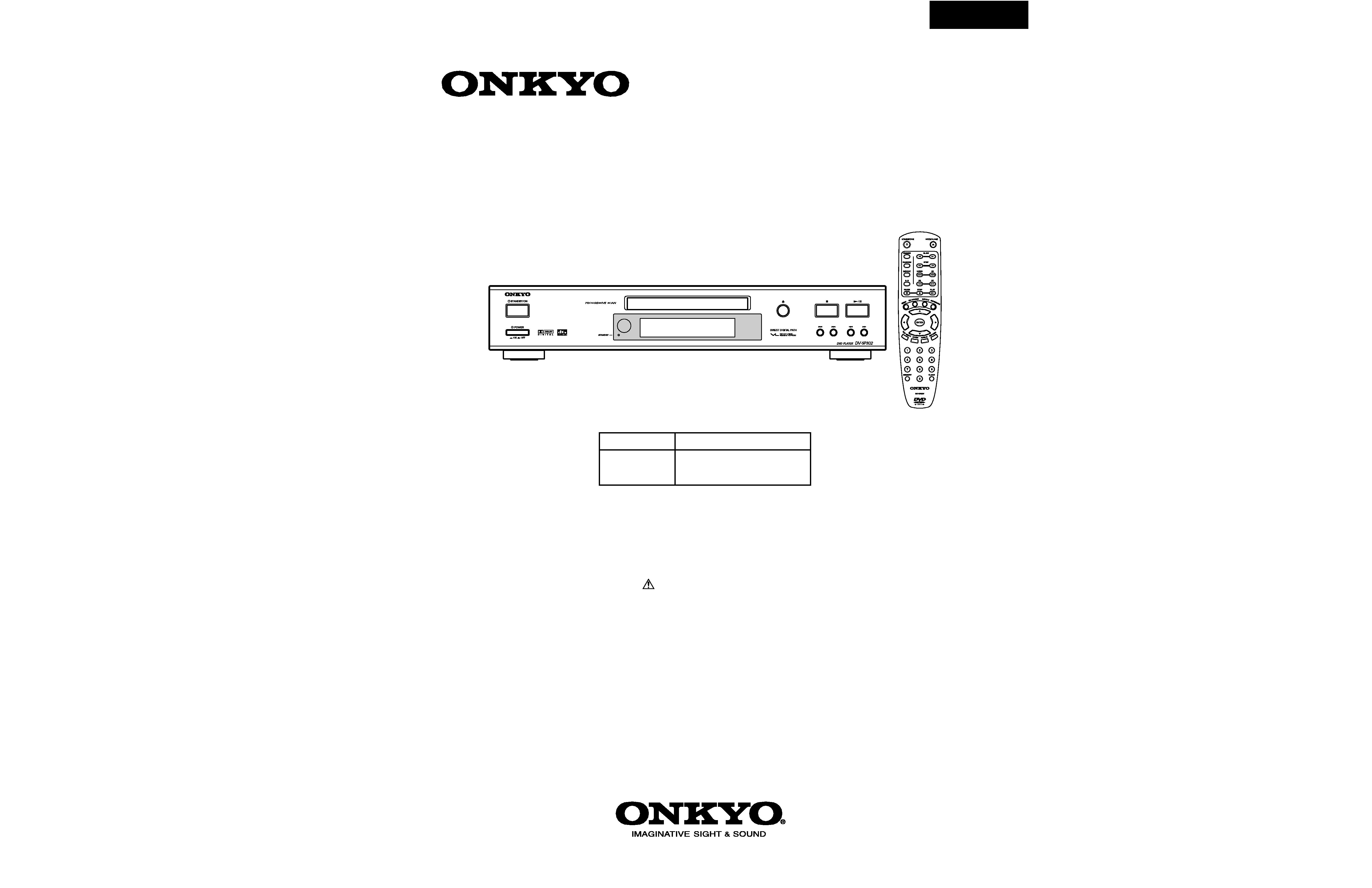
DV-SP302
SERVICE MANUAL
SERVICE MANUAL
DVD PLAYER
Black, Silver and Golden models
MODEL
DV-SP302
Ref. No. 3814
092004
120V AC, 60Hz
CDD
CUA, CUT,
CUK, CUR
100-240V AC, 50/60Hz
RC-575DV
SAFETY-RELATED COMPONENT
WARNING!!
THE MARK
FOUND ON SOME COMPONENT
PARTS INDICATES THE CRITICAL FOR RISK OF
FIRE AND ELECTRIC SHOCK.
WHEN REPLACING, BE SURE TO USE PARTS OF
IDENTICAL DESIGNATION.
MAKE LEAKAGE-CURRENT OR RESISTANCE
MEASUREMENTS TO DETERMINE THAT EXPOSED
PARTS ARE ACCEPTABLY INSULATED FROM THE
SUPPLY CIRCUIT BEFORE RETURNING THE
APPLIANCE TO THE CUSTOMER.

DV-SP302
SPECIFICATIONS
DVD Player
Power supply
AC 120 V, 60 Hz (North America models)
AC 100-240 V, 50/60 Hz (Other models)
Power consumption
16 W
Weight
6.6 lbs, 3.0 kg
External dimensions (W x H x D)
17-1/8" x 3-3/16" x 11-1/8"
435 x 82 x 283 mm
Signal system
PAL/NTSC
Frequency response
Digital output
4 Hz to 22 kHz (48 kHz sampling)
DVD linear sound
4 Hz to 44 kHz (96 kHz sampling)
Signal-to-noise ratio (digital output)
More than 90 dB
Audio dynamic range (digital output)
More than 90 dB
Harmonic distortion (digital output)
Less than 0.008%
Wow and flutter
Below measurable level
Outputs
Video output
1.0 V (p-p), 75 ohm negative sync., pin jack
S-video output
(Y) 1.0 V (p-p), 75 ohm negative sync.,
(C) 0.286 V (p-p), 75 ohm Mini DIN 4-pin
PAL: (C) 0.300 V (p-p)
Component video output
(Y) 1.0 V (p-p), 75 ohm negative sync.,
(PB)/(PR) 0.7 V (p-p), 75 ohm pin jack
Audio output
Optical digital output
-22.5 dBm, optical connector
Coaxial digital output
0.5 V (p-p), 75 ohm pin jack
Analog output
2.0 V (rms), 100 ohm pin jack (L, R)
Specifications and features are subject to change without notice.
DV-SP302
SERVICE PROCEDURE-1
SAFETY CHECK
(Only U.S.A. model)
After correcting the original service problem perform the
following safety check before releasing the set to the customer
Connect the insulating-resistance tester between the plug of
power supply cord and terminal GND on the back panel.
Specifications: More than 10M ohm at 500V
The lightning flash with arrowhead symbol, within an equilateral triangle, is
intended to alert the user to the presence of uninsulated "dangerous voltage"
within the product's enclosure that may be of sufficient magnitude to constitute
a risk of electric shock to persons.
The exclamation point within an equilateral triangle is intended to alert the user
to the presence of important operating and maintenance (servicing) instruction
in the literature accompanying the appliance.
RISK OF ELECTRIC SHOCK
DO NOT OPEN
WARNING
AVIS
RISOUE DE CHOC ELECTRIQUE
NE PAS OUVRIR
This unit contains a semiconductor laser system and is classified as a
"CLASS 1 LASER PRODUCT". So, to use this model properly, read
this Instruction Manual carefully . In case of any trouble, please contact
the store where you purchased the unit. To prevent being exposed to the
laser beam, do not try to open the enclosure.
CAUTION:
VISIBLE LASER RADIATION WHEN OPEN AND INTERLOCK
FAILED OR DEFEATED. DO NOT STARE INTO BEAM.
CAUTION:
THIS PRODUCT UTILIZES A LASER. USE OF CONTROLS OR
ADJUSTMENTS OR PERFORMANCE OF PROCEDURES OTHER
THAN THOSE SPECIFIED HEREIN MAY RESULT IN
HAZARDOUS RADIATION EXPOSURE.
The label on the right is
applied on the rear
panel except for USA
and Canadian models.
1. This unit is a CLASS 1 LASER PRODUCT and employs a laser
inside the cabinet.
2. To prevent the laser from being exposed, do not remove the
cover. Refer servicing to qualified personnel.
"CLASS 1 LASER
PRODUCT "
LASER CAUTION
CAUTION
VISIBLE AND INVISIVLE LASER RADIATION
WHEN OPEN DO NOT STARE INTO THE BEEM OR
VIEW DIRECTLY WITH OPTICAL INSTRUMENTS.
DO NOT PRESS ON THIS SURFACE
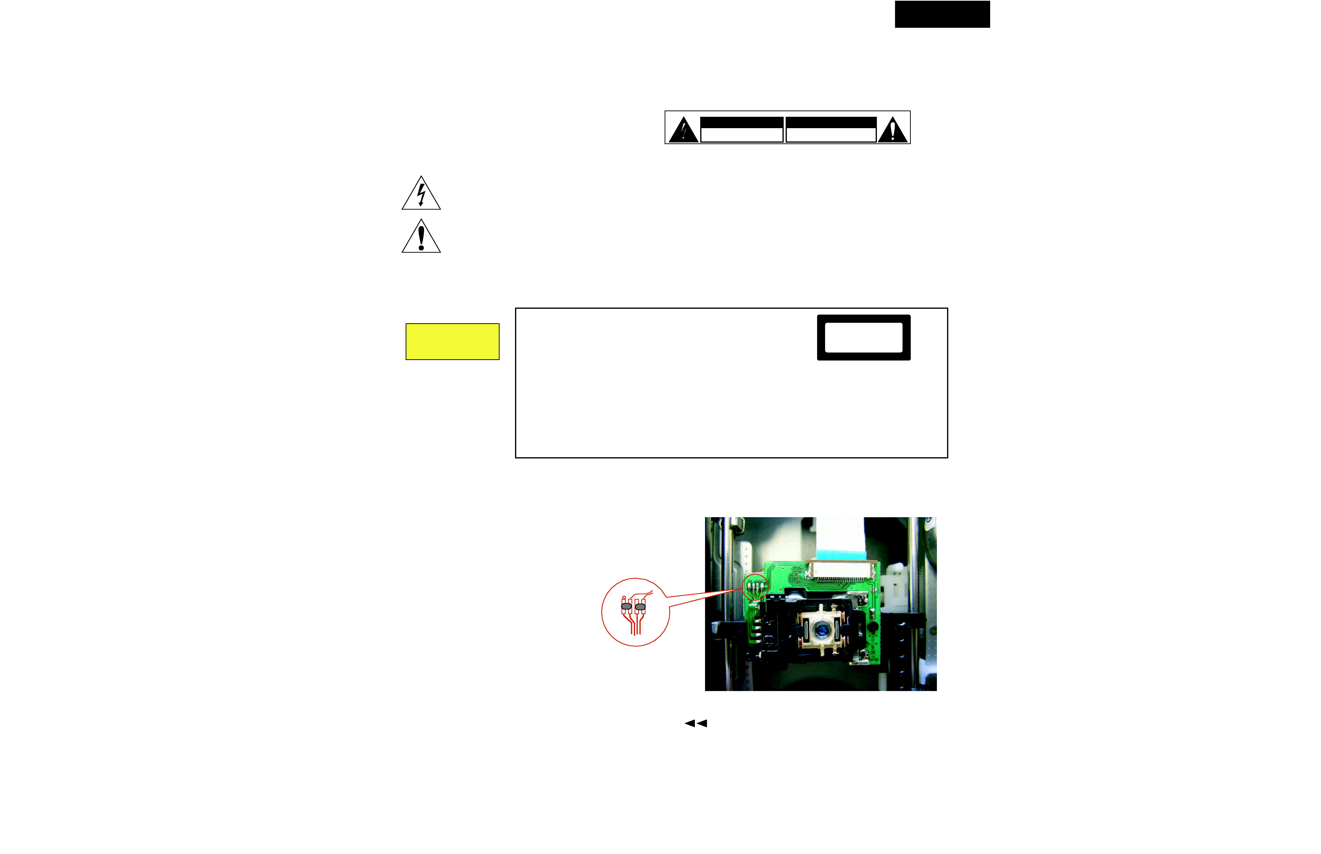
1.Remove the solder of Laser Diode shorting
1-1
Remove the bracket magnet.
1-2
Shorting the short land with solder.
1-3
Remove the FFC and other connectors.
2. Factory setting (Initial setting)
2-1 Open the tray. Press 2 second the search button
and
power key on remote controller (RC-575DV).
2-2 Displayed version of firmware on the FL tube.
2-3. At above condition, turn off the mechanical power switch.
Bottom side
Fig-1
DV-SP302
SERVICE PROCEDURE-2
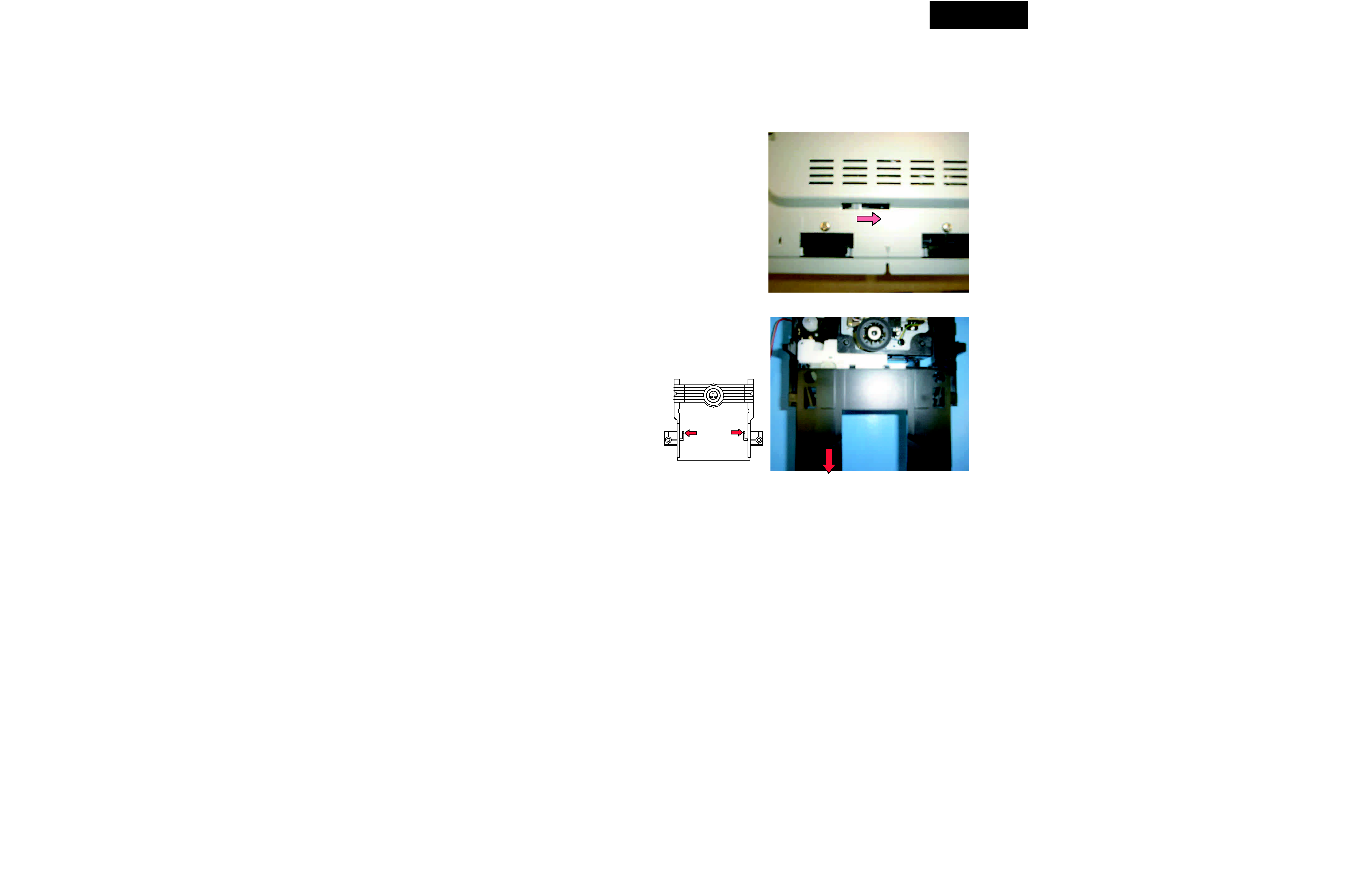
Replace the DVD mechanism
1. Remove the top cover (six screws)
2. Remove two screws of both side of front panel.
3. Remove the bracket mecha. (two screws).
4. Shift the cam slider on bottom side. (See Fig-1)
5. Remove the tray.
6. Remove FFC, connector and one screw.
7. A tray is drawn out extending a nail. (See Fig-2)
Tray
DV-SP302
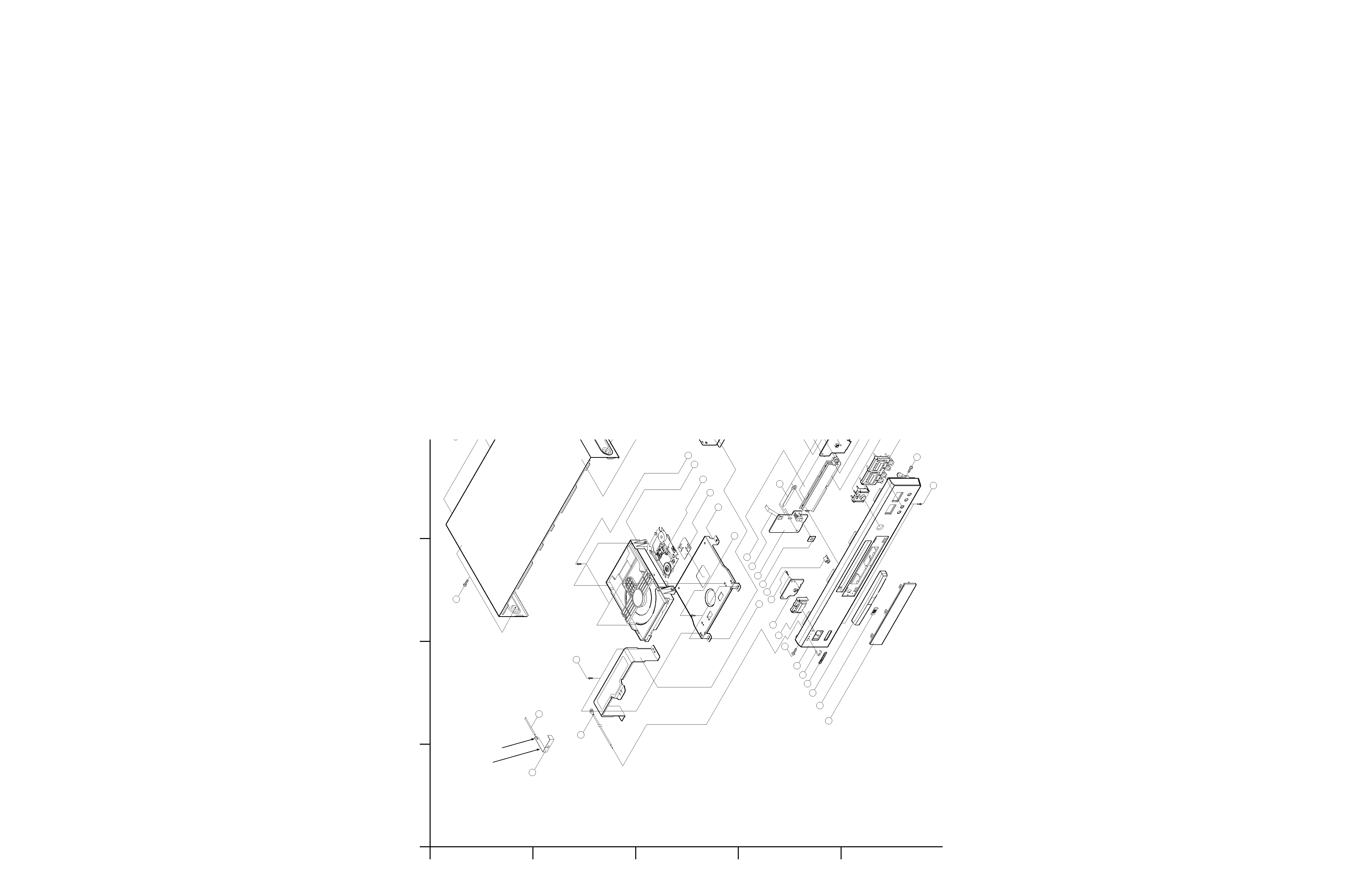
EXPLODED VIEW
A
1
2
3
4
5
B
C
DE
FG
H
S7 x2
S6
12
13
14
15
4
S5
x 11
S3
17
18
S3
17
18
S2 x 2
S3
17
18
19
20
21
S2 x 4
S2
22
23
24
10
9
8
7
6
38
S6
5
4
25
26
27
28
S8
S4 x 11
30
29
S1 x 3
S2 x 2
31
36
x 3
32
S3 x 2
33
S2 x 4
34
37
16
11
S2 x 2
4
1
4
2
3
S5
x 3
35
S2 x 2
39
1) Insert a plate in a panel front. Thereafter
2) Insert a wire in a hole of palte
and do soler.
39
38
S3
18
17
40
40
S1 : 3 x 18 W/ Washer
S2 : 3 x 8 ZNY/ BH
S3 : 3 x 10 BK/ BH
or 3 x 8 Silver/ BH
S4 : 3 x 10 BK/ BH DOT
S5 : 2.6 x 8 ZNY/ PH
S6 : 3 x 8 BK/ FH
S7 : 3 x 10 BK/ BH
or 3 x 8 W/ Washer
S8 : 3 x 6 BK/ BH
S3 x 3
S3 x 2