RC-469DV
DV-C503
SERVICE MANUAL
SERVICE MANUAL
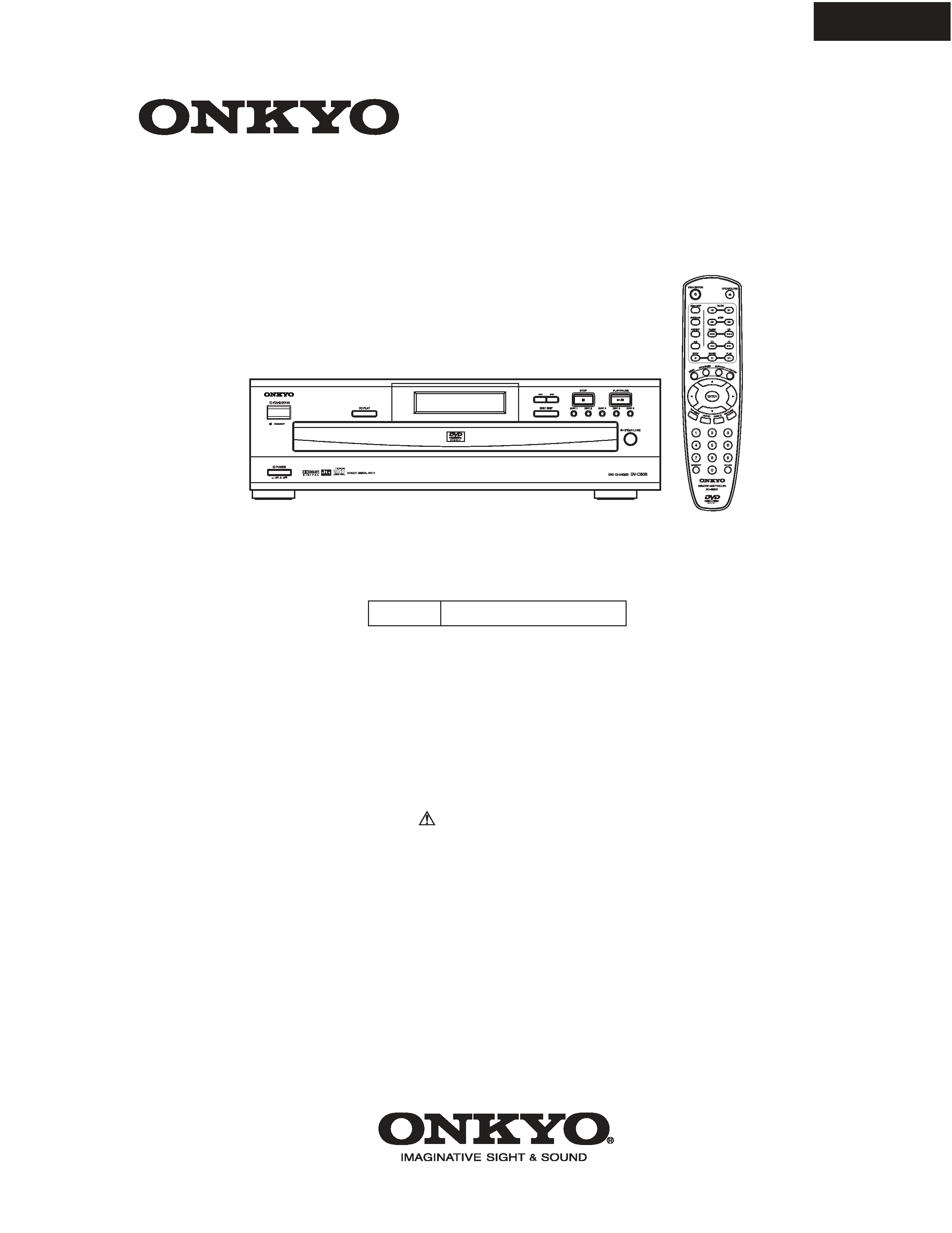
DVD Changer
Black model
MODEL
DV-C503
120V AC, 60Hz
BUDD
Ref. No. 3704
102001
SAFETY-RELATED COMPONENT
WARNING!!
THE MARK
FOUND ON SOME COMPONENT
PARTS INDICATES THE CRITICAL FOR RISK OF
FIRE AND ELECTRIC SHOCK.
WHEN REPLACING, BE SURE TO USE PARTS OF
IDENTICAL DESIGNATION.
MAKE LEAKAGE-CURRENT OR RESISTANCE
MEASUREMENTS TO DETERMINE THAT EXPOSED
PARTS ARE ACCEPTABLY INSULATED FROM THE
SUPPLY CIRCUIT BEFORE RETURNING THE
APPLIANCE TO THE CUSTOMER.
Specifications and features are subject to change without notice.
DVD Changer
Power supply
AC 120 V, 60 Hz
Power consumption
20 W
Weight
15.0 lbs
External dimensions
17 1/8" x 5 1/16" x 16 15/16 " (W/H/D)
Signal system
NTSC
Frequency range (digital audio)
48 kHz sampling 4 Hz to 22 kHz
96 kHz sampling 4 Hz to 42 kHz
Signal-to-noise ratio (digital audio)
More than 98 dB
Audio dynamic range (digital audio)
More than 95 dB
Harmonic distortion (digital audio)
Less than 0.005 %
Wow and flutter
Below measurable level
Operating conditions
Temperature: 5 C to 35 C (41 F to 95 F), Operation status: Horizontal
Outputs
Video output
1.0 V (p-p), 75 ohm , negative sync., pin jack
1
S-video output
(Y) 1.0 V (p-p), 75 ohm, negative sync.
(C) 0.286 V (p-p), 75 ohm, Mini DIN 4-pin
1
Component video output
(Y) 1.0 V (p-p), 75 ohm, negative sync., pin jack
1
(P B)/(PR) 0.7V(p-p), 75 ohm , pin jack 2
Audio output (digital output Optical)
Optical connecter
1
Audio output (digital output Coaxial)
0.5 V (p-p), 75 ohm, pin jack
1
Audio output (analog output)
2.0 V (rms), 320 ohm, pin jack (L, R)
2
Supplied Accessories
Audio/video connection cable
1
Remote controller (RC-469DV)
1
Batteries (size AAA/R3)
2
DV-C503
SPECIFICATIONS
DV-C503
SERVICE NOTE
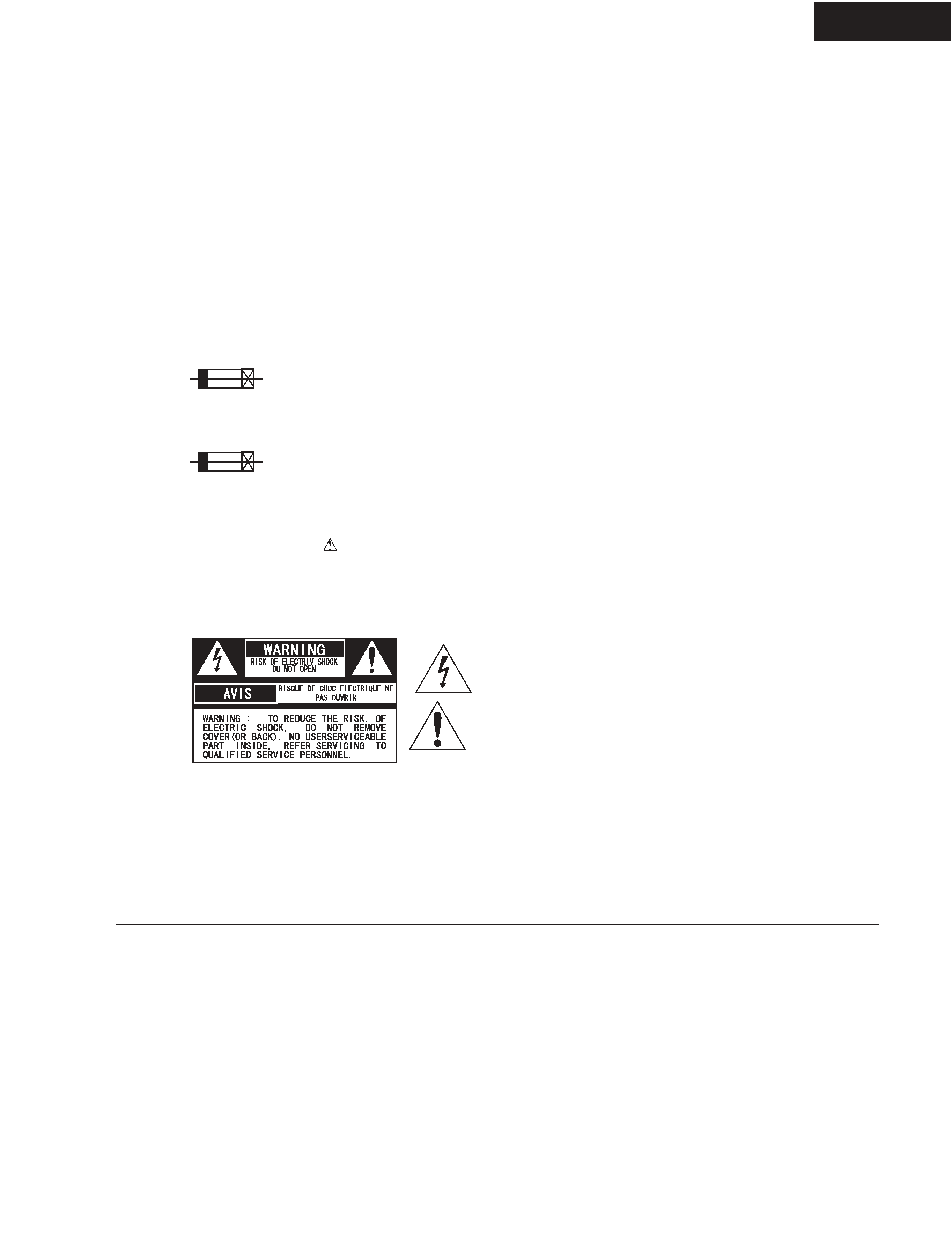
1. Replacing the fuses
2. Safety-check out
(Only U.S.A. model)
After correcting the original service problem perform the
following safety check before releasing the set to the customer
Connect the insulating-resistance tester between the plug of
power supply cord and terminal GND on the back panel.
Specifications: More than 10M ohm at 500V
REF.NO.
PART NO.
DESCRIPTION
F1
252159
2A-UL/T-237
This symbol located near the fuse indicates that the
fuse used is show operating type, For continued protection against
fire hazard, replace with same type fuse , For fuse rating, refer to
the marking adjust to the symbol.
Ce symbole indique que le fusible utilise est e lent.
Pour une protection permanente, n'utiliser que des fusibles de meme
type. Ce demier est indique la qu le present symbol est apposre.
TO REDUCE THE RISK OF FIRE OR ELECTRIC SHOCK, DO NOT EXPOSE THIS APPLIANCE TO RAIN
OR MOISTURE. DANGEROUS HIGH VOLTAGES ARE PRESENT INSIDE THE ENCLOSURE. DO NOT OPEN THE
CABINET. REFER SERVICING TO QUALIFIED PERSONNEL ONLY.
TO PREVENT ELECTRIC SHOCK, MATCH WIDE BLADE OF PLUG TO WIDE SLOT, FULLY INSERT.
POUR EVITER LES CHOCS ELECTRIQUE, INTRODUIRE LA LAME LA PLUS LARGE DA LA FICHE DANS LA
BORNE CORRESPONDANTE DA LA PRISE ET POUSSER JUSQU' AU FOND.
WARNING :
CAUTION :
ATTENTION :
The lightning flash with arrowhead symbol, within an equilateral triangle, is
intended to alert the user to the presence of uninsulated "dangerous voltage"
within the product's enclosure that may be of sufficient magnitude to constitute
a risk of electric shock to persons.
The exclamation point within an equilateral triangle is intended to alert the user
to the presence of important operating and maintenance (servicing) instruction
in the literature accompanying the appliance.
1. Ground for the work-desk.
Place a conductive sheet such as a sheet of copper (with impedance lower than 10Mohm) on the work-desk and
place the set on the conductive sheet so that the chassis.
2. Grounding for the test equipments and tools.
Test equipments and toolings should be grounded in order that their ground level is the same the ground of the power source.
3. Grounding for the human body.
Be sure to put on a wrist-strap for grounding whose other end is grounded.
Be particularly careful when the workers wear synthetic fiber clothes, or air is dry.
4. Select a soldering iron that permits no leakage and have the tip of the iron well-grounded.
5. Do not check the laser diode terminals with the probe of a circuit tester or oscilloscope.
PRECAUTIONS
LASER CAUTION
Initialization of setup
1. Press the "DISC 4" and "CDPLAY" key to the same timing.
The "DISC 4 key is pushed previously.
Then, light off the FL tube.
2. Push the power switch.
S5
H1
H13
H4
H3
H2
S2
H43
42
S2
H5
S4
S5
H7
H8
H10
11
H12
H21
H47
H47
U2
H15
H14
S2
H20
S2
H22
H49
H48
H47
H22
H23
S2
U3
S2
H44
S2
S2
S6
S3
S6
H45
S2
S1
S2
H47
H41
S2
H46
H27
H24
U1
H26
H27
S2
H38
S2
H37
H35
S3
H34
S2
H6
F1
CN01
S3
S3
S6
S4
S4
S2
S2
S2
S2
S2
S2
S2
H26
H26
S2
S1
S1
S2
S2
S6
S2
S2
S2 CC201
CC202
H52
FL tu
be
H47
H47
H42
S2
H42
S1
S2
U2
U2
H53
DV-C503
DV-C503
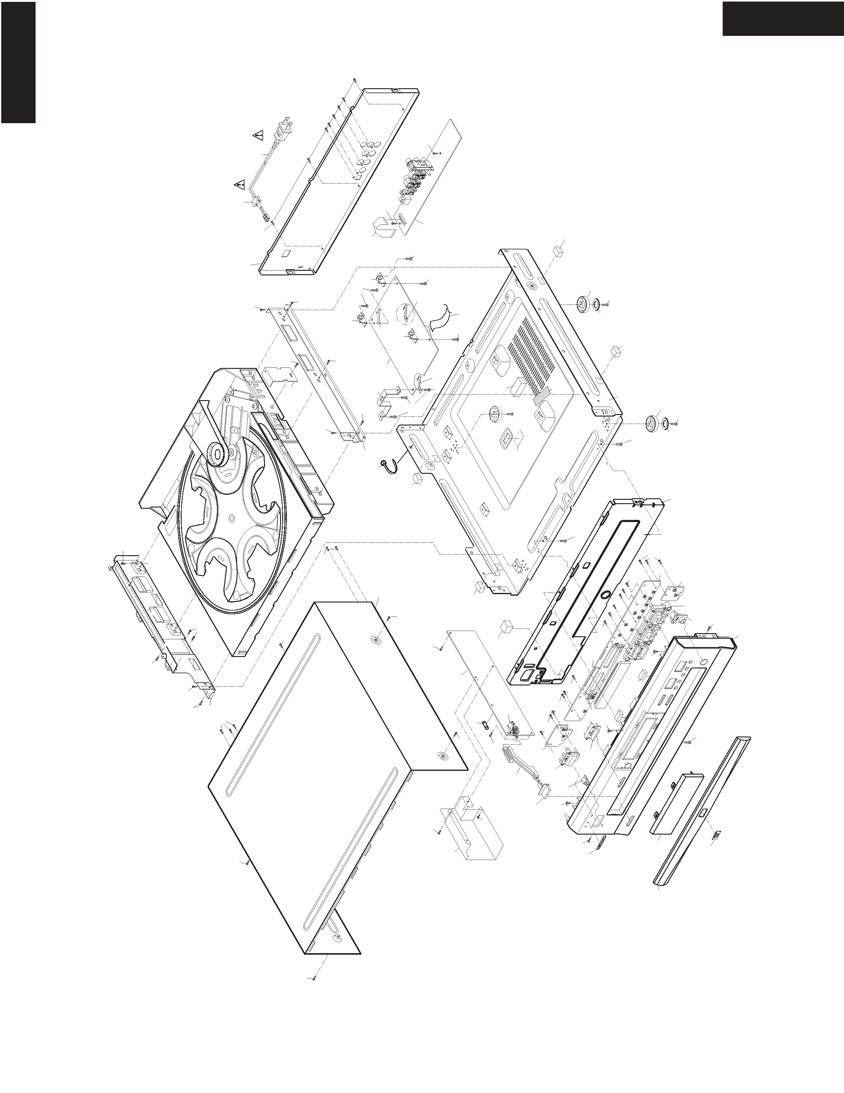
EXPLODE VIEW
CHASSIS
DV-C503
PARTS LIST
CHASSIS
REF. NO. PART NO.
DESCRIPTION
H1
55221110
Plate, DVD
H2
55184480
Drawer panel
H3
55221120
Clear plate
H4
55186750
Badge Logo
H5
55186710
Facet
H6
55244650
Button, STANDBY
H7
55244620
Knob, POWER
H8
55184600
Shaft, power
H10
55244670
Button, PLAY
H12
55164930
FL holder
H13
55184330
Front panel
H14
55244660
Button, OPEN/CLOSE
H15
55244680
Button, Keys (9-keys)
H20
55236110
Front chassis
H21
55201610
Sponge, front bracket
H22
55125120
Foot (4)
H23
55196510
Sponge, chassis
H24
55174580
Bracket ground
H26
55186640
Bracket main PC board
H27
55178960
Spring
H34
55011170
Power cord, 1830mm
H35
55125180
Cord bushing
H37
55186610
Rear panel
H38
55174610
Bracket R small
H41
55186600
Top cover
H42
55141370
Rubber (4)
H42
55127310
Washer foot
H43
55184690
Power supply board unit
H44
55221140
Shield cover
H45
55186670
Bracket L, Frame
H46
55186680
Bracket R, Frame
H47
55174550
Cushion, 12 x 8 x 20
H48
55186620
Main chassis
H49
55190690
Rubber sheet
H52
55170390
Wire tie
H53
55190770
Sheet
S1
838130068
3TTB+6B, Self tapping screw
S2
838130088
3TTB+8B, Self tapping screw
S3
838130108
3TTB+10B(BC), Self tapping screw
S4
831130088
3TTW+8B, Self tapping screw
S6
838440088
4TTB+8B(BC), Self tapping screw
U1
55183100
Main circuit PC board
U2
55183110
Display PC board,
Open/Close SW PC board,
Standby LED PC board
U3
55183120
Output terminal PC board
F1
NOTE: THE COMPONENTS IDENTIFIED BY MARK
ARE CRITICAL FOR RISK OF FIRE AND
ELECTRIC SHOCK. REPLACE ONLY WITH
PART NUMBER SPECIFIED.
REF. NO. PART NO.
DESCRIPTION
252159
2A-UL/T-237, Fuse