DTA-9.4
SERVICE MANUAL
SERVICE MANUAL
SEVEN CHANNEL AMPLIFIER
Black model
MODEL
DTA-9.4
120V AC, 60Hz
BUDD
Ref. No. 3750
May, 2003
SAFETY-RELATED COMPONENT
WARNING!!
COMPONENTS IDENTIFIED BY MARK
ON THE
SCHEMATIC DIAGRAM AND IN THE PARTS LIST ARE
CRITICAL FOR RISK OF FIRE AND ELECTRIC SHOCK.
REPLACE THESE COMPONENTS WITH ONKYO
PARTS WHOSE PART NUMBERS APPEAR AS SHOWN
IN THIS MANUAL.
MAKE LEAKAGE-CURRENT OR RESISTANCE
MEASUREMENTS TO DETERMINE THAT EXPOSED
PARTS ARE ACCEPTABLY INSULATED FROM THE
SUPPLY CIRCUIT BEFORE RETURNING THE
APPLIANCE TO THE CUSTOMER.

DTA-9.4
SPECIFICATIONS
Amplifier section
Continuous average power output
(FTC Power, Rated Power) (Measured with AES-17 LPF)
Front L/R:
120 Watts per channel min. RMS. Into
8 ohms 2 channel driven, from 20 to
20,000 Hz with no more than 1 % total
harmonic distortion.
240 Watts per channel min. RMS. Into
4 ohms 2 channel driven, 1,000 Hz
with no more than 1.5 % total
harmonic distortion.
Center:
120 Watts min. RMS. Into 8 ohms 1
channel driven, from 20 to 20,000 Hz
with no more than 1 % total harmonic
distortion.
240 Watts min. RMS. Into 4 ohms 1
channel driven, 1,000 Hz with no more
than 1.5 % total harmonic distortion.
Surround L/R:
120 Watts per channel min. RMS. Into
8 ohms 2 channel driven, from 20 to
20,000 Hz with no more than 1 % total
harmonic distortion.
240 Watts per channel min. RMS. Into
4 ohms 2 channel driven, 1,000 Hz
with no more than 1.5 % total
harmonic distortion.
Surround Back:
120 Watts per channel min. RMS. Into
8 ohms 2 channel driven, from 20 to
20,000 Hz with no more than 1 % total
harmonic distortion.
240 Watts per channel min. RMS. Into
4 ohms 2 channel driven, 1,000 Hz
with no more than 1.5 % total
harmonic distortion.
Dynamic Power Output
2 x 350 Watts at 2 ohms
2 x 267 Watts at 4 ohms
2 x 162 Watts at 8 ohms
Total Harmonic Distortion
(Measured with AES-17 LPF)
1 % at rated power (1 kHz)
0.01 % at 1 watt output (1 kHz)
Damping Factor
25 at 8 ohms 1 kHz
Input Sensitivity and Impedance
1 V, 5 k ohms (Unbalanced)
2 V, 10 k ohms (Balanced)
5 - 12V dc (12V Trigger)
Frequency Response
10 Hz to 60 kHz : +1 dB, 3 dB (8 ohms)
Signal to Noise Ratio
115 dB (IHF-A, 1 V input / Unbalanced
or 2 V input / Balanced)
General
Power Supply
AC 120 V, 60 Hz
Power Consumption
5.3 A
Power Consumption
in standby mode
3.8 W
Input terminals
Analog Audio:
Unbalanced (RCA type) x 7
Balanced (XLR type) x 7
Control:
12V TRIGGER (CONTROL LINK)
Power supply:
AC INLET (IEC type)
Output terminals
Analog Audio:
Speakers x 7
Dimensions (W x H x D)
Weight
39.0 lbs.
Specifications and features are subject to change
without notice.
17-1/8" x 6-7/8" x 17-13/16"
DTA-9.4
Power
Standby
Power
Standby
Power
Standby
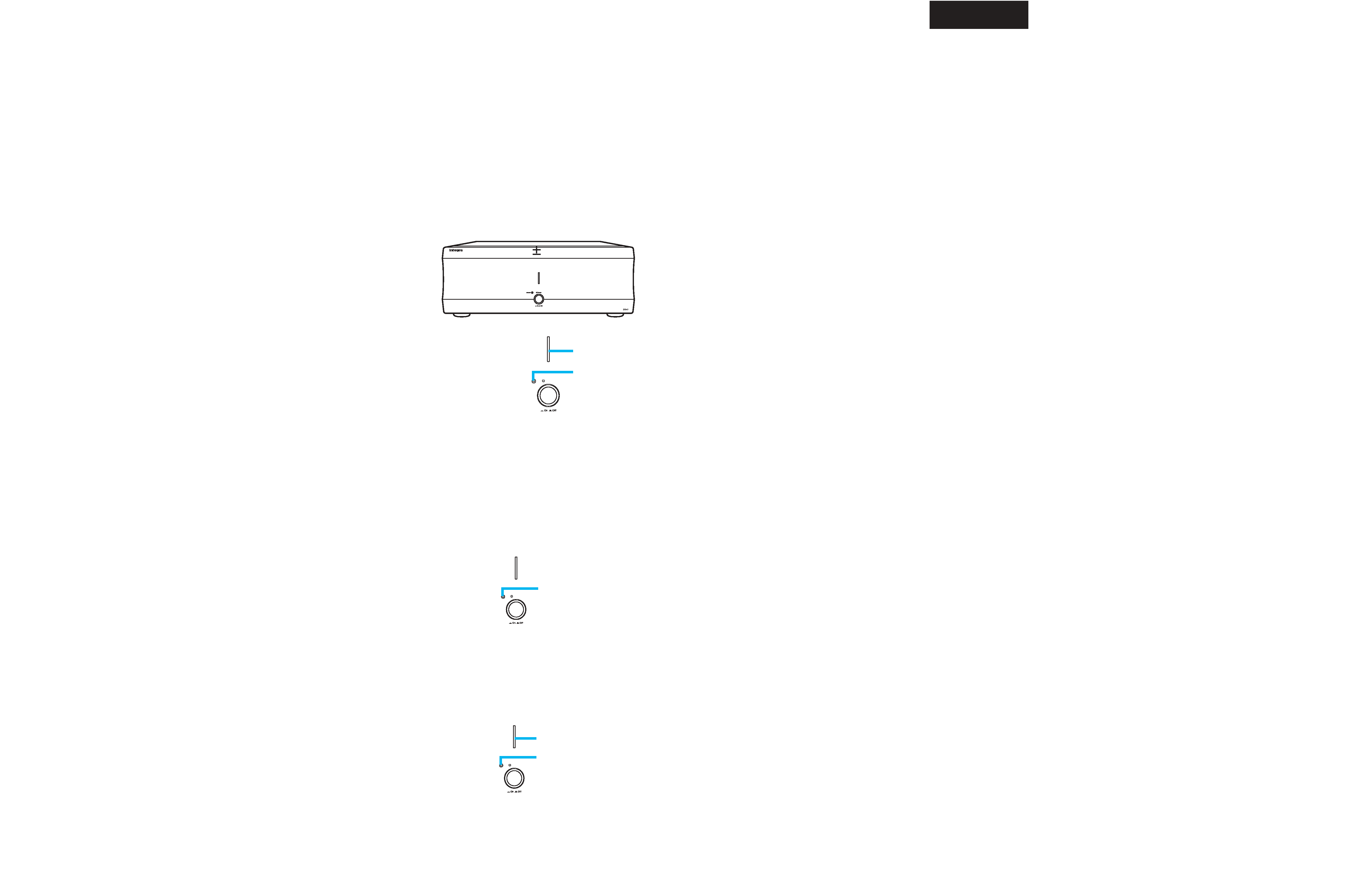
OPERATION CHECK-1
CHECK THE DC POWER SUPPLY CURRENT DETECTION
Notes
No load and No signal input.
How to check?
1. Remove the top cover.
2. Connect the power supply card to a wall outlet.
4. Power On the unit.
5. Short-circuit the both ends of P161 on NAPS-7789. An object should be in the following states.
Lights
Blinks
Lights
Blinks
How to check?
2. Connect the power supply card to a wall outlet.
4. Power On the unit.
5. Immediately after power switch On.
4. About 1 second after turning On a power supply.
5. About 10 seconds after turning On a power supply.
Check
Blinks stop
Check
Check
RL501 and RL502 Relays ON.
Check
RL701 Relays ON.
CHECK THE RELAYS AND INDICATORS
A423
A421
A420
A424
A431
A431
A019
A426
A002
A001
A047
A050
A019
A030
A031
A032
A032
A035
A025
A026
A037
A028
Q881
Q882
Q883
Q884
Q842
A037
A044
A044
A024
A025
A042
A042
A044
A071
A071
A070
A070
A049
A023
A050
A047
A401
A012
A402
A402
A402
A403
A010
P001
L997
L998
A018
A020
A018
A018
A008
A007
A009
A007
A016
A085
A085
A086
A086
A087
A087
A017
A011
P651
A013
A021 A014
A014
A015
Q506
Q505
Q511
Q512
P193
A010
F901
F9801
A044
A044
A041
A041
A041
A043
A028
A037
A045
A027
A061
A060
A027
A039
D101
D102
D103
D104
D902
D901
A078
A076
A078
A075
A080
A081
A005
A003
A004
A006
A425
A421
A427
A422
A430
DTA-9.4
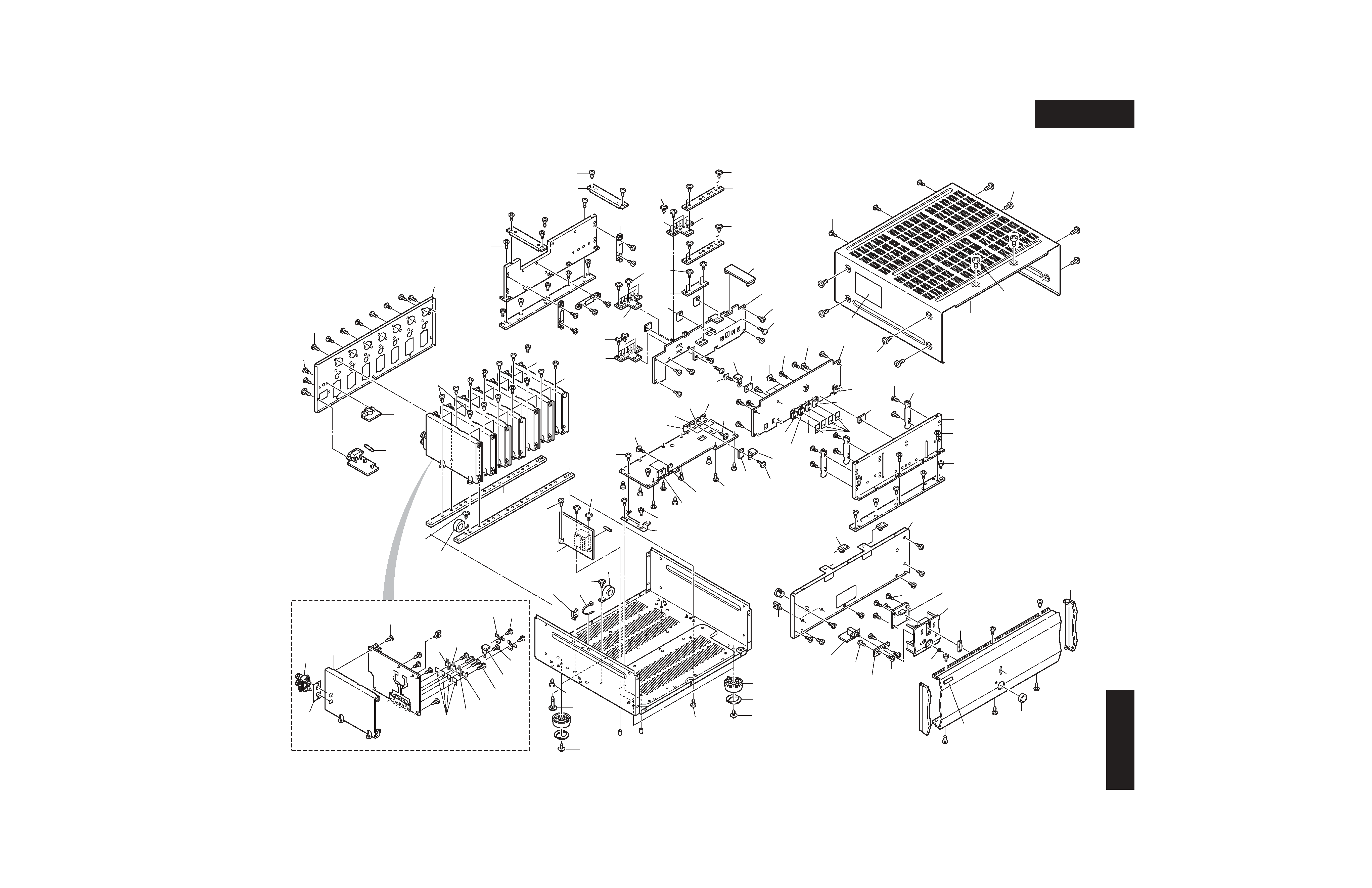
EXPLODED VIEW
DTA-9.4
A
1
2
3
4
5
B
C
DE
FG
H
DTA-9.4
DTA-9.4
Q303
10.4dB
INPUT
Q301
10.4dB
Q301
10.4dB
2
3
2
1
3
Hot
Cold
Q302
0dB
RCA
XLR
XLR
RCA
Q303
0dB
XLR Type
RCA Type
Q302
0dB
2
6
LPF
(6.7dB)
+3V
+3V
Q405-Q408
LPF
Q507-Q510
(7.4dB)
Q507-Q510
(7.4dB)
+7V
+7V
+B+(27V)
-B
RL501
RL501
+B
-B(+27V)
RL502
RL502
Q716
70kHz LPF
70kHz LPF
SPEAKER
OUTPUT
Q709
R710 (PTC Themistor)
Q701
Q704
Q717
Q751, Q752
+5V
Temperature or
Current
Warning indicator
D751
Q580, Q581
AC INLET
AC 100V
50/60Hz
RL901
C909-C912
T901
D101 - D104
C103-C106
Bus plate
Bus plate
Bus plate
Full Bridge Type
High-Brid Type
(PFM & PWM)
D902 Triac
D903-D906
D941-D944
Q843-Q845
D901
Q848
Q841,Q842
+5V
+5V
Q881-Q884 FET
Q869-Q876
Q817
F901
12A/250V
F901
1A/125V
POWER
T9801
RL701
Q708,Q715
+5V
DC Output
Warning
D705
Q9801,Q9802
Q9821,9820
-27V
Q717
D9801-D9804
Q711
Q9810,Q9811
Q9808
Q9806
Q9813-Q9815
Q9832-Q9833
Q9804
Q9822
+B (+27V)
GND
-B (-27V)
+12V
+5V
P9910
12V TRIGGER
CONTROL LINK IN
Q9812
D9812
D9813
Power
(Blue)
Standby/Warning
(Red)
U15: NAAF-7797
POWER AMPLIFIER PC BOARD
U16: NAAF-7798
TEMPERATURE SENSOR
PC BOARD
U16: NAPS-7792
TRIGGER TERMINAL PC BOARD
U8: NAETC-7794
DISPLAY LED PC BOARD
U7: NAPS-7793
CONTROL PC BOARD
U7: NASW-7795
POWER SWITCH PC BOARD
U5: NAPS-7790
SWITCHING CONTROL
PC BOARD
U1: NAPS-7788
PRIMARY POWER SUPPLY
PC BOARD
T902
U2: NAPS-7788
SECONDARY POWER SUPPLY
PC BOARD
Q701
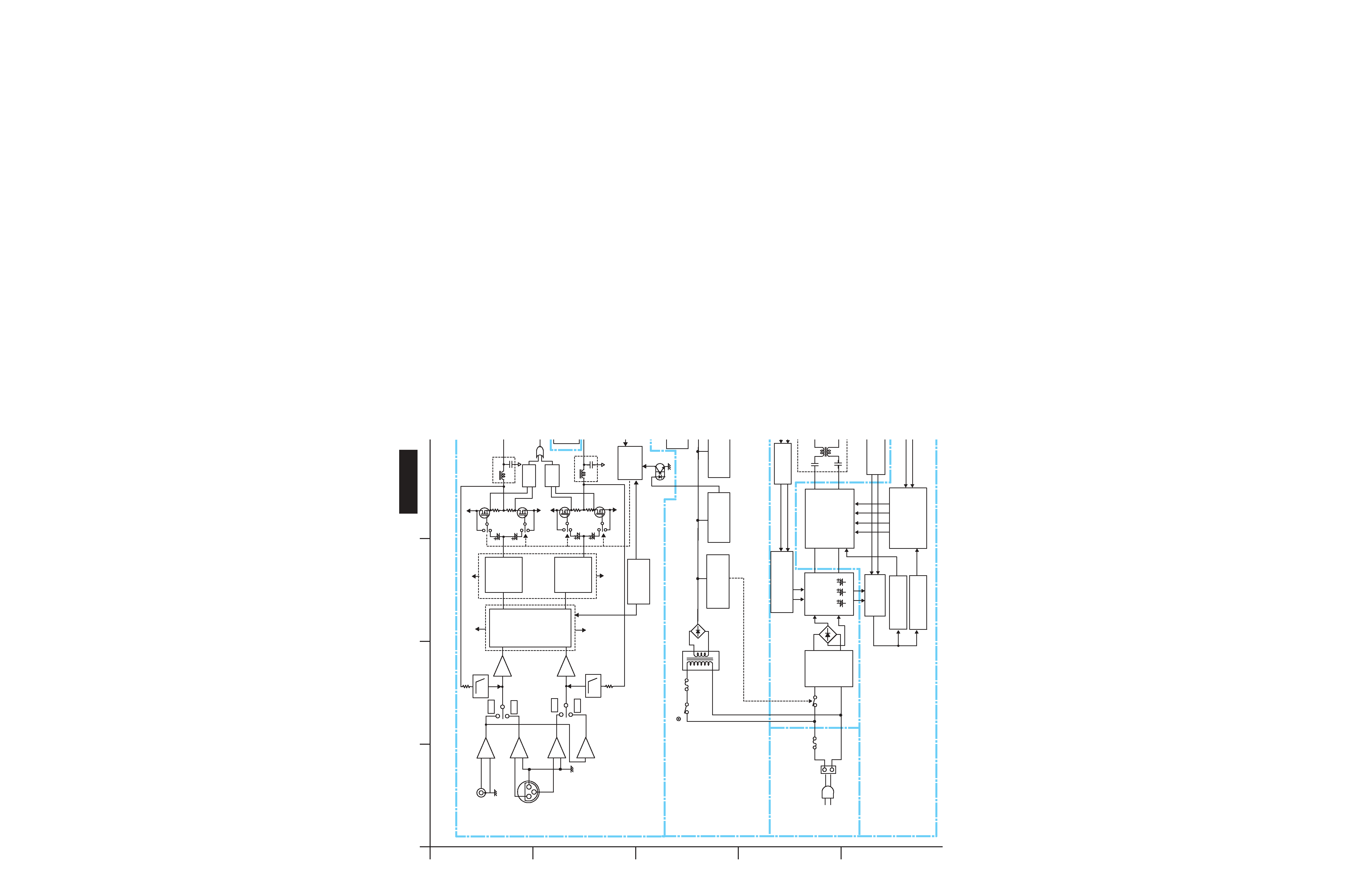
BLOCK DIAGRAMS
Smoothing
Capacitor
Resonance
Circuit
Switching
circuit
Start Circuit
NFB
DC Offset
Detection
Line Filter
PWM
Modurator
MOS FET
Driver
MOS FET
Driver
Over Current
Detection
MOS FET Temperature
Detection Cuircuit
Detection
Circuit
Current Protection
and
Temperature protection
Circuit
Error amplififer
Circuit of
Output voltage
Smoothing
Coil
Output
Capacitor Arrey
MOS FET
Relay Driver
High-Frequency
Transformer
High-Speed
Rectifer Diode
Control circuit
Start,Stop
Muting Circuit
Sub Transformer
Power Relay
Control circuit
MOS FET
Muting Circuit
Sreaker Output Relay
Control Circuit
Reset IC
Multi Vibrator
Rectifier Circuit
Reset
12V Trigger/
Cotrol Link
Detection Circuit
LED Driver
Constant Voltage
Power Supply
Constant Voltage
Power Supply
Constant Voltage
Power Supply
Inrush current
Prevention Circiuit
Rectifier Circuit
Speaker Output
Relay Driver