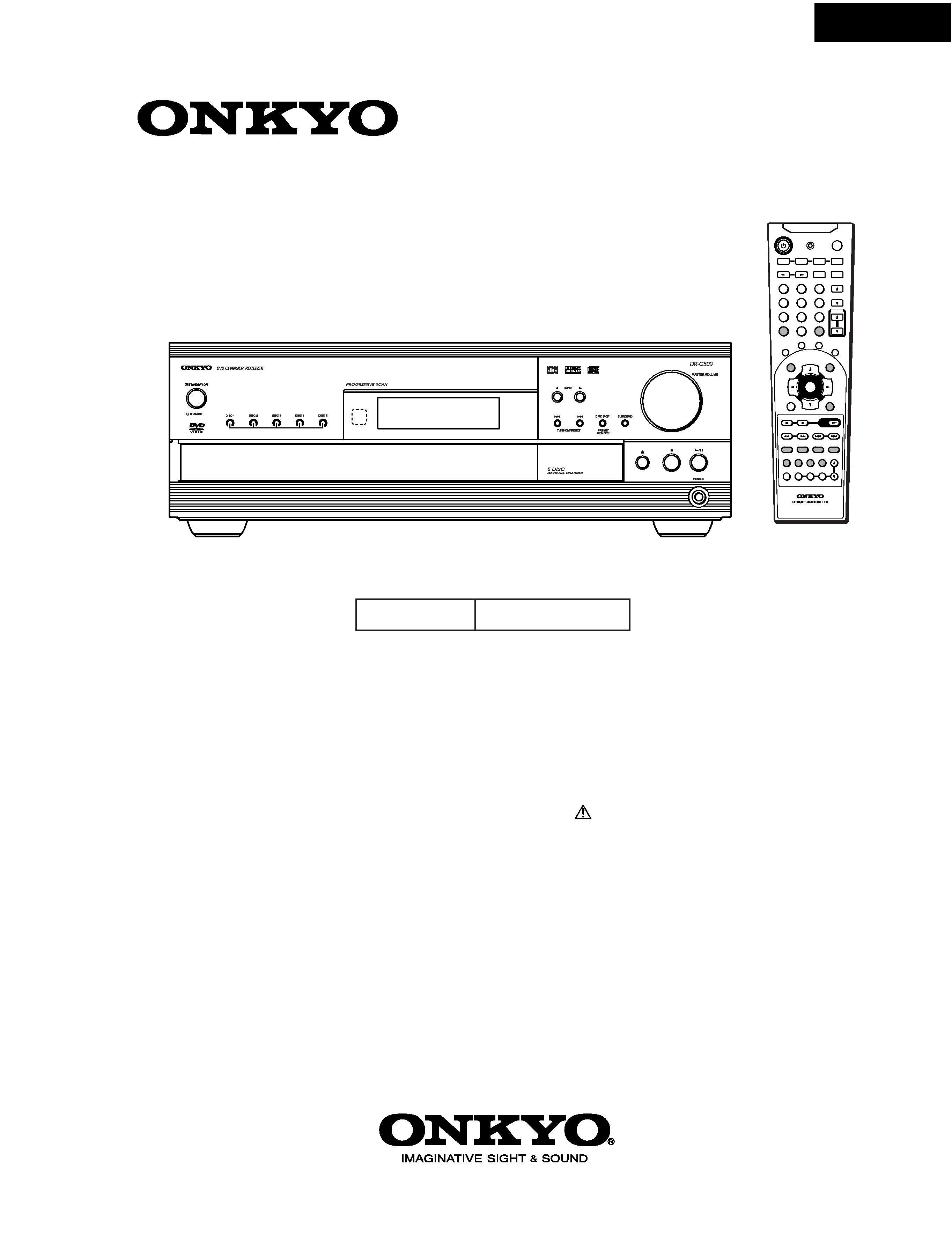
DR-C500
SERVICE MANUAL
DVD CHANGER RECEIVER
Black and Silver models
MODEL
DR-C500
120V AC, 60Hz
BMDD1N
Ref. No. 3747
092002
RC-508M
-- / ---
SEND/LEARN
TOP MENU
MENU
RETURN
ON SCREEN
CH
CH
VOLUME
UP
DOWN
TV/VCR
S
TA
NDB
Y / O
N
EN
TER
LIGHT
DVD
RCVR/VCR
T V
CBL / SAT
INPUT
DIMMER
SLEEP
MASTER
VOLUME
PRESET
123
456
789
MEM
CLR
0
R
EP
EA
T
A-B
RANDOM
MU
TIN
G
ENTER
PLAY
PLAY
SP A
SP B
FM MODE
SURROUND
SP SETUP
IPM
ACOUSTIC
CONTROL
LATE
NIGHT
AUDIO ANGLE SUBTITLE ZOOM
SW MODE T.TONE
CH SEL DISTANCE
PRGV
DISC
SLOW
STEP
RC-
504M
MODE
+
SAFETY-RELATED COMPONENT
WARNING!!
COMPONENTS IDENTIFIED BY MARK
ON THE
SCHEMATIC DIAGRAM AND IN THE PARTS LIST ARE
CRITICAL FOR RISK OF FIRE AND ELECTRIC SHOCK.
REPLACE THESE COMPONENTS WITH ONKYO
PARTS WHOSE PART NUMBERS APPEAR AS SHOWN
IN THIS MANUAL.
MAKE LEAKAGE-CURRENT OR RESISTANCE
MEASUREMENTS TO DETERMINE THAT EXPOSED
PARTS ARE ACCEPTABLY INSULATED FROM THE
SUPPLY CIRCUIT BEFORE RETURNING THE
APPLIANCE TO THE CUSTOMER.

DR-C500
SPECIFICATIONS
AMPLIFIER SECTION
Power Output (FTC)
All channels 40 watts per channel min.
RMS. into 6 ohms two channel driven,
1,000 Hz with no more than 5 % total
harmonic distortion.
Continuous power output (DIN)
All channels 30 watts per channel min.
RMS. into 6 ohms two channel driven,1,000 Hz
Continuous Power output (EIAJ)
All channel 45 watts per channel min.
RMS. into 6 ohms two channel driven,1,000 Hz
Dynamic Power 6 ohms: 42 W (L/R)
8 ohms: 35 W (L/R)
Total Harmonic Distortion 5 % at rated power
0.2 % at 1 watt output
IM Distortion 5 % at rated power
0.2 % at 1 watt output
Damping Factor 40 at 8 ohms
Input Sensitivity and Impedance
VIDEO 1 DIGITAL INPUT (OPT) 21 to 15 dBm
VIDEO 2 DIGITAL INPUT (COAX) 0.5 Vp-p, 75 ohms
LINE (VIDEO 1, VIDEO 2/CDR/PC, TV/LINE, TAPE/MD/HD)
200 mV/50 kohms
Composite (VIDEO 1, VIDEO 2/CDR/PC) 1 Vp-p, 75 ohms
S-VIDEO (VIDEO 1, VIDEO 2/CDR/PC)Y: 1 Vp-p, 75 ohms
C: 0.28 Vp-p, 75 ohms
Output Level and Impedance
DIGITAL OUTPUT (OPT) 21 to 15 dBm
REC OUT (TAPE/MD/HD, VIDEO 2/CDR/PC) 200 mV, 2.2 kohms
PRE OUT (SUBWOOFER) 1 V, 470 ohms
Composite (MON OUT, VIDEO 1) 1 Vp-p, 75 ohms
S-VIDEO (MON OUT, VIDEO 1) Y: 1 Vp-p, 75 ohms
C: 0.28 Vp-p, 75 ohms
COMPONENT VIDEO OUTPUT Y: 1.0 Vp-p, 75 ohms
PB/PR: 0.7 Vp-p, 75 ohms
Frequency Response
20 to 30,000 Hz : +/ 0.8 dB
Acoustic Control
1: +9 dB at 120 Hz
2: +9 dB at 120 Hz
+6 dB at 10,000 Hz
Signal-to-noise Ratio
100 dB (0.5 V INPUT LINE)
Muting
50 dB
DVD SECTION
Signal readout system
Optical non-contact
Linear velocity
3.49 m/s (Single Layer)
3.84 m/s (Dual Layer)
Error correction system
Reed Solomon Product Code
Signal system NTSC
Regional restriction code
1
Laser
Semiconductor laser, wavelength 650 nm
Frequency response
10 Hz to 44 kHz (96 kHz)
Signal-to-noise ratio (digital audio)
More than 100 dB
Audio dynamic range (digital audio)
More than 93 dB
Harmonic distortion (digital audio)
Less than 0.025%
Wow and flutter
Below threshold of measurability
Operating conditions
Temperature: 5 C to 35 C (41 F to 95 F),
Operation status: Horizontal
TUNER SECTION
Tuning Range
FM: 87.50 to 108.00 MHz (50 kHz steps)
AM: 530 to 1710 kHz (10 kHz steps)
Usable Sensitivity
FM: Mono 11.2 dBf, 1.0 µV (75 ohms IHF)
0.9 µV (75 ohms DIN)
Stereo 17.2 dBf, 2.0 µV (75 ohms IHF)
23 µV (75 ohms DIN)
AM: 30 µV
50 dB Quieting Sensitivity
FM: Mono 17.2 dBf, 2.0 µV (75 ohms)
Stereo 37.2 dBf, 20.0 µV (75 ohms)
Capture Ratio
FM: 2.0 dB
Image Rejection Ratio
FM: 40 dB
AM: 40 dB
IF Rejection Ratio
FM: 90 dB
AM: 40 dB
Signal-to-noise Ratio
FM: Mono 73 dB, IHF
Stereo 67 dB, IHF
AM: 40 dB
Alternate Channel Att. (+/ 400 kHz)
FM: Mono 55 dB, IHF
Selectivity FM: 50 dB, DIN 55dB, IHF
AM Suppression Ratio
FM: 50 dB
Harmonic Distortion
FM: Mono 0.2 %
Stereo 0.3 %
AM: 0.7 %
Frequency response
FM: 30 to 15,000 Hz (+/ 1.0 dB)
Stereo Separation
FM: 45 dB at 1,000 Hz
30 dB at 100 to 10,000 Hz
Stereo Threshold
FM: 17.2 dBf, 20 µV (75 ohms)
GENERAL
Power Supply Rating and Power Consumption
AC 120 V, 60Hz 2.0 A
Dimensions (W x H x D)
435 x 101 x 428 mm (171/8 x 4 x 1613/16 ins.)
Weight
8.8 kg (19.4 lb.)
Specifications and features are subject to change without notice.
DR-C500
1
3
6
5
9
2
4
8
7
10
15
14
13
12
11
1
3
6
5
9
2
4
8
7
10
14
13
12
11
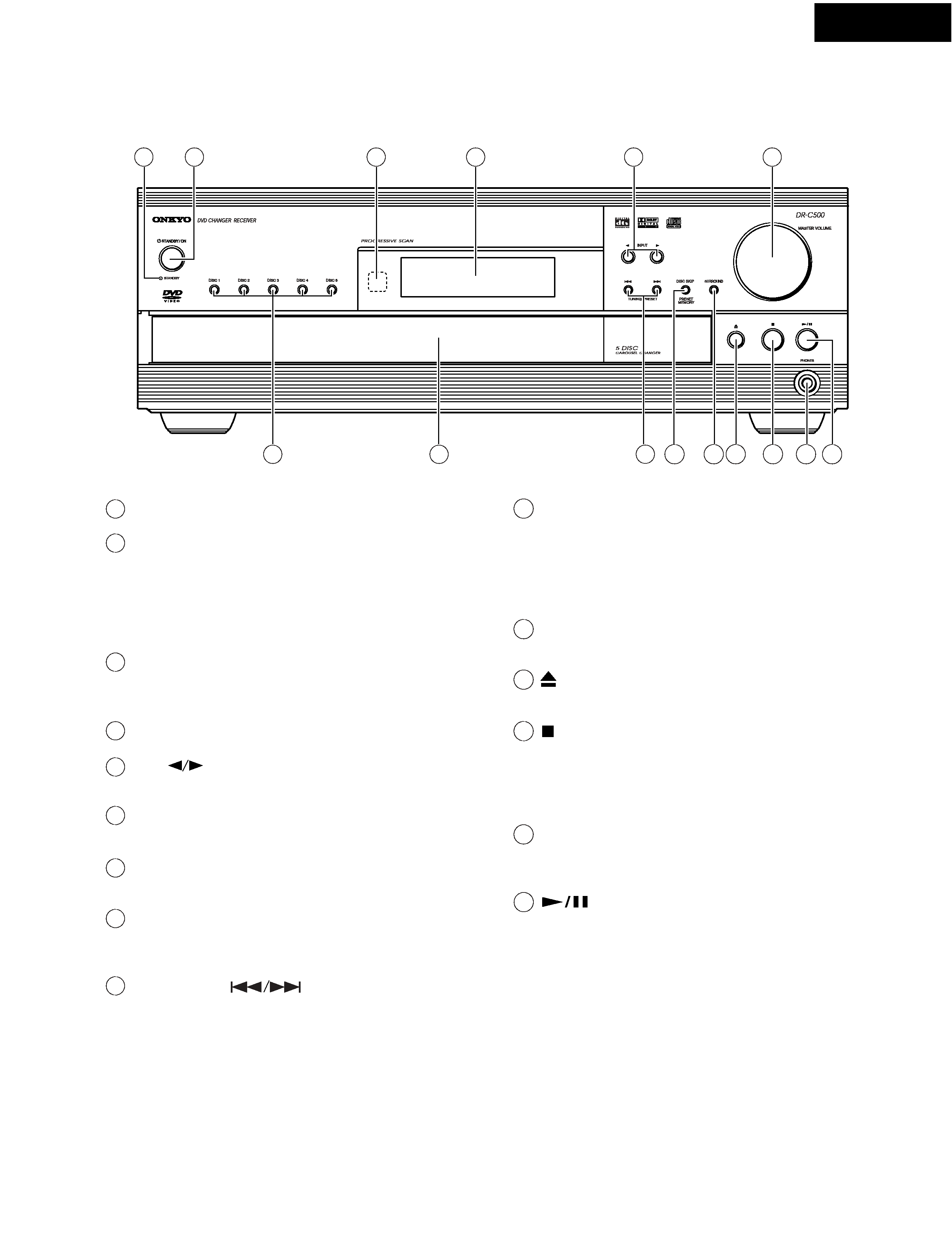
STANDBY indicator
STANDBY/ON button
When STANDBY/ON button is pressed to ON, the DVD Changer
Receiver turns on. The STANDBY indicator turns off and the
display lights up. Pressing the button again returns the DVD
Changer Receiver to the standby state. This state turns off the
display and disables control functions.
Remote control sensor
Point the remote controller toward the remote control sensor to
operate the DVD Changer Receiver.
Display
INPUT
buttons
Press to select the input source.
MASTER VOLUME dial
The MASTER VOLUME dial is used to control the volume level.
DISC 1, DISC 2, DISC 3, DISC 4, DISC 5 buttons
Press to select a disc in the changer.
Disc tray
When loading a disc, place it on the disc tray with its label facing
up.
TUNING/PRESET
buttons
When playing discs, press to skip back or forward to consecutive
chapters/tracks. When listening to the radio, press to change the
tuner frequency or select preset stations.
PRESET MEMORY/DISC SKIP button
When listening to the radio, press to assign the radio station that is
currently tuned in to a preset channel or delete a previously preset
station. When playing discs, press to select a disc. When the DISC
SKIP button is pressed while the Disc tray is open, the tray simply
rotates.
SURROUND button
Press to select a surround mode.
button
Press to open and close the disc tray.
button
Press to stop playback. Pressing once enables playback to
resume from a point shortly before the location where it was
stopped. Pressing twice causes the disc to return to the
beginning of the disc when playback starts again.
PHONES jack
This is a standard stereo jack for connecting stereo
headphones.
button
Press to start or pause playback.
15
PANEL VIEWS-1
FRONT PANEL
DR-C500
1
3
6
16
5
9
2
4
8
7
17
18
10
15
14
13
12
11
19
20
1
3
6
16
5
9
2
4
8
7
17
18
10
15
14
13
12
11
19
20
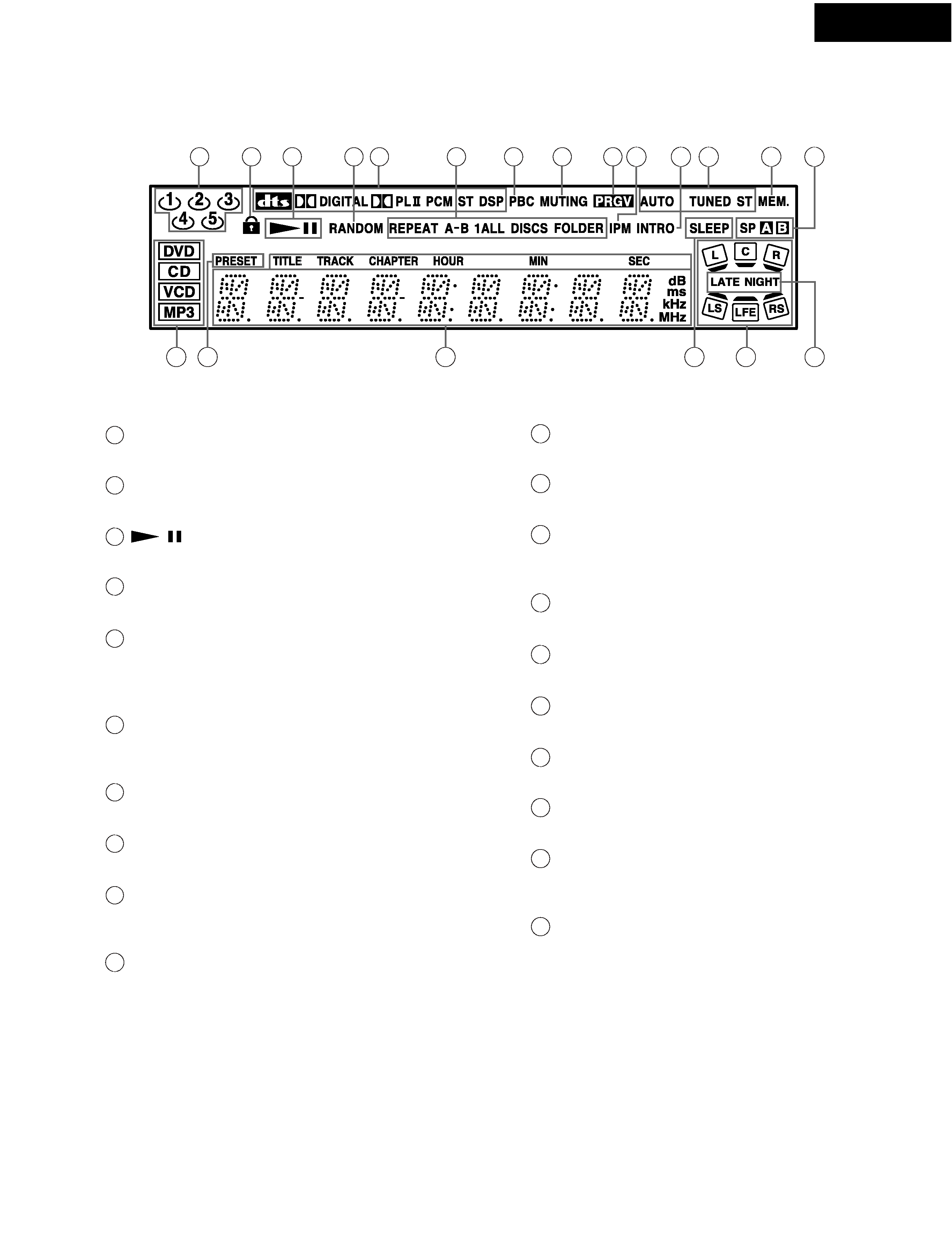
Disc number indicators
Indicate the presence of a disc.
Parental Lock indicator
Illuminates in parental lock mode.
,
indicators
Illuminate in play or pause mode.
RANDOM indicator
Illuminates during random playback.
Source/Listening mode indicators
One of the source indicators lights to show the format of the current
source. In addition, one of the listening mode indicators lights
according to the current listening mode.
REPEAT indicators
Illuminate during repeat playback. REPEAT indicator also
illuminates during A-B repeat playback.
PBC indicator
Illuminates when PBC is on for Video CD.
MUTING indicator
Flashes when the mute function is active.
PRGV indicator
Illuminates when the DVD Changer Receiver is set to progressivescan
video.
IPM (Intelligent Power Management) indicator
Lights up when the IPM function is active.
INTRO indicator
Lights up during intro-scan playback.
AUTO, TUNED, ST indicators
Illuminate to indicate the reception mode.
MEM. indicator
Illuminates when the MEM button is pressed in the radio
station preset operation and during DVD memory play.
Speaker indicators
Illuminate to indicate the selected speakers.
Inserted disc indicators
Illuminate to indicate the type of disc that is playing currently.
PRESET indicator
Illuminates when tuned to a preset station.
Multipurpose display
Indicates operating status, messages, etc.
SLEEP indicator
Lights up when the sleep timer is active.
Speaker setup indicators
Indicate the speaker configuration. Light to show speaker
positions, input and output signals for each channel.
LATE NIGHT indicator
Illuminates when the unit is in Late Night mode.
PANEL VIEWS-2
DISPLAY
DR-C500
1
3
6
5
9
2
4
8
7
10
Y
PB
PR
COMPONENT VIDEO
L
R
R
L
R
L
R
L
IN
IN
IN
IN
OUT
OUT
VIDEO
1
VIDEO
2
PRE OUT
COAXIAL
OPTICAL
OPTICAL
IN
OUT
MONI
OUT
VIDEO
2
VIDEO
1
IN
IN
OUT
DIGITAL
OUT
SUB
WOOFER
DIGITAL IN
VIDEO 2
VIDEO 1
TAPE /CD-R
TV/LINE
AUDIO
FRONT
SPEAKERS
A
B
SURROUND
SPEAKERS
CENTER
SPEAKER
VIDEO
S VIDEO
MODEL NO.
DR-C
500
DVD CHANGER RECEIVER
REGIONAL CODE
1
WARNING
RISK OF ELECTRIC SHOCK
DO NOT OPEN
RISQUE DE CHOC ELECTRIQUE
NE PAS
OUVRIR
AVIS
ANTENNA
ANTENNA
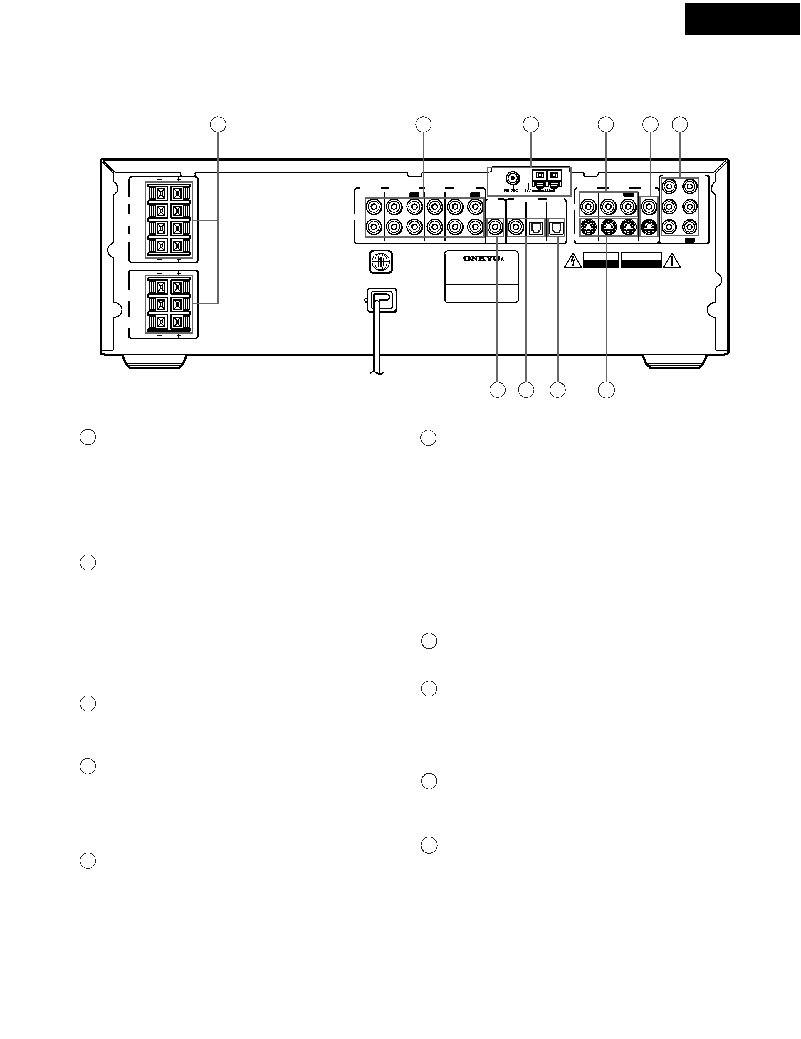
FRONT SPEAKERS A/B, SURROUND SPEAKERS and
CENTER SPEAKER terminals
FRONT SPEAKERS: system: To enjoy home theater sound.
Speaker terminals are provided for the front left, front right, center,
surround left and surround right speakers.
FRONT SPEAKERS: system: To enjoy stereo sound. Speaker
terminals are provided for the front left and front right.
AUDIO (TV/LINE IN / TAPE/CD-R IN/OUT /
VIDEO 1 IN/OUT / VIDEO 2 IN) jacks
These are the analog audio inputs and outputs. There are 4 audio
inputs and 2 audio outputs. The audio inputs and outputs require
RCA type connectors.
When connecting a VCR or other video component, make sure you
connect the audio and video leads to the same set of jacks (i.e.,
both to VIDEO 1).
ANTENNA terminals
These terminals are for connecting the FM antenna and AM
antenna.
VIDEO (VIDEO 1 IN/OUT / VIDEO 2 IN) jacks
There are 2 video inputs and 1 output. Connect LD players, VCRs
or other video components to the video inputs. The video output
channel can be used to be connected to a video tape recorder for
making recordings.
MONI OUT jacks
The monitor output includes both RCA type and S video
configurations. This output is for connecting a television monitor or
projector.
COMPONENT VIDEO IN/OUT jacks
If your TV has component inputs, you can connect a component
video cable to the component input of your TV and to the
COMPONENT VIDEO OUT jack of your DVD Changer Receiver for
ideal video quality.
a DVD player or other device has component video out jacks,
If you can directly input a component signal to the COMPONENT
VIDEO IN jack.
The component video cable only carries the video signal;
remember to connect the left and right audio cables.
If you connect a TV that is compatible with a Progressive scan
signal, you can enjoy both Interlaced and Progressive scan.
SUB WOOFER PRE OUT jack [16]
This terminal is for connecting an active subwoofer.
DIGITAL IN (VIDEO 1 OPTICAL, VIDEO 2 COAXIAL) jacks
These are the digital audio inputs. There is 1 digital input with an
optical jack and 1 with a coaxial jack. The inputs accept digital
audio signals from MD players, hard disk recorders, CD players,
or other digital source component.
DIGITAL OUT (OPTICAL) jack
This jack is for connecting an MD recorder, CD recorder, hard disk
recorder or other component with optical fiber cable.
S VIDEO (VIDEO 1 IN/OUT / VIDEO 2 IN) jacks
There are 2 S Video inputs and 1 output. Connect LD players,
VCRs or other video components to the video inputs. The S Video
output channel can be used to be connected to video tape recorder
for making recordings. The S-Video cable only carries the video
signal. Remember to connect the left and right audio cables.
1
3
6
5
2
4
9
8
7
10
PANEL VIEWS-3
REAR PANEL