DPS-8.3
SERVICE MANUAL
SERVICE MANUAL
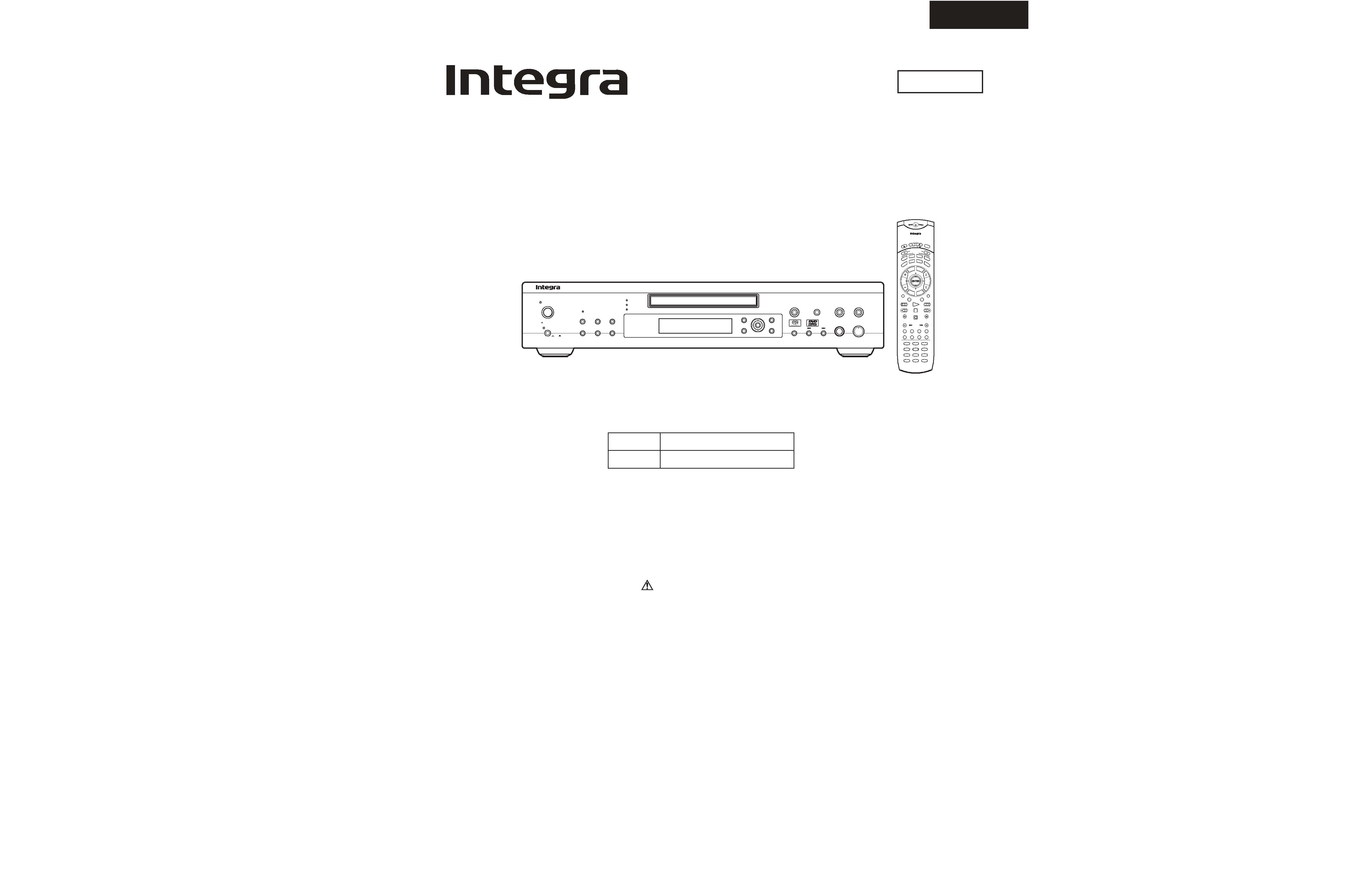
SACD & DVD AUDIO/VIDEO PLAYER
Black model
MODEL
DPS-8.3
120V AC, 60Hz
230-240V AC, 50Hz
BMDD
MPA4P
Ref. No. 3743
Oct., 2002
RC-499DV
Setup
Menu
Top Menu
Return
Push to Enter
Cursor
Display
Clear
Random
Last Memory
Repeat
Play
Stop
Pause
Open /Close
Standby/On
Standby
On
O f f
Video Circuit
Off
Dimmer
Power
Phones Level
Phones
SACD
DVD
CD
RC-499DV
Mode
On
Standby
Input Selector
Audio SEL
Video Off
Display
Dimmer
TV / VCR
Step/ Slow
Pause
Step/ Slow
Muting
Enter
A-B
Picture
Cond M
Function M
Speed
Surround
Random
Program
Clear
Repeat
-- / ---
VOL
CH
Light
Search
1
2
3
45
6
7
8
9
+10
0
Au
dio
Angl
e
To
p M
enu
Menu
Retu
rn
Setu
p
M
DIM
DIS
A
RPT
RND
PGM
CLR
A-B
PIC
C.M
F. M
DV
D
TV
VCR
RCVR
Subttl
Las
t M
TV.VCR
/
Schematic diagram & Printed circuit board view only
SAFETY-RELATED COMPONENT
WARNING!!
THE MARK
FOUND ON SOME COMPONENT
PARTS INDICATES THE CRITICAL FOR RISK OF
FIRE AND ELECTRIC SHOCK.
WHEN REPLACING, BE SURE TO USE PARTS OF
IDENTICAL DESIGNATION.
MAKE LEAKAGE-CURRENT OR RESISTANCE
MEASUREMENTS TO DETERMINE THAT EXPOSED
PARTS ARE ACCEPTABLY INSULATED FROM THE
SUPPLY CIRCUIT BEFORE RETURNING THE
APPLIANCE TO THE CUSTOMER.

DPS-8.3
SPECIFICATIONS
General
Power supply
USA & Canadian models
AC 120 V, 60 Hz
Australian model
AC 230 - 240, V 50 Hz
Power consumption
USA & Canadian models
43 W
Australian model
39 W
Power consumption in standby mode
USA & Canadian models
9.3 W
Australian model
9.9 W
Weight
5.0 kg, 11.0 lbs.
External dimensions
435
91
317 mm (W/H/D), 17-1/8"
3-9/16"
12-1/2"
DVD Player
Signal system
USA & Canadian models
Standard NTSC
Australian model
PAL/AUTO
Regional restriction code
USA & Canadian areas
1
Australian areas
4
Laser
Semiconductor laser, wavelength 650/780 nm
Frequency range (digital audio)
DVD linear sound:
48 kHz sampling 4 Hz to 22 kHz
96 kHz sampling 4 Hz to 44 kHz
DVD-Audio:
192 kHz sampling 4 Hz to 96 kHz
Audio CD:
4 Hz to 20 kHz
SACD:
4 Hz to 96 kHz
Signal-to-noise ratio (digital audio)
More than 118 dB
Audio dynamic range (digital audio)
More than 100 dB
Harmonic distortion (digital audio)
Less than 0.001 %
Wow and flutter
Below measurable level (less than ±0.001 % (W.PEAK))
Operating conditions
Temperature: 5 C to 35 C, Operation status: Horizontal
Outputs
Video output
1.0 V (p-p), 75 ohm, negative sync., pin jack
2
S-video output
(Y) 1.0 V (p-p), 75 ohm, negative sync., Mini DIN 4-pin
2
(C) 0.286 V (p-p), 75 ohm
Component Signal output
(Y) 1.0 V (p-p), 75 ohm, negative sync., pin jack
1, BNC
1
(Pb)/ (Pr) 0.7 V (p-p), 75 ohm
Audio output (digital output Optical)
- 22.5 dBm
2
Audio output (digital output Coaxial)
0.5 V (p-p), 75 ohm, pin jack
1
Audio output (analog audio)
2.0 V (rms), 440 ohm, pin jack (L, R)
2
Audio output (5.1 channel analog audio) 2.0 V (rms), 440 ohm, pin jack (Lo/Lt, Ro/Rt, SL1, SR1, C, SW)
1
1.4 V (rms), 440 ohm, pin jack (SL2, SR2)
1
Specifications and features are subject to change without notice.
x
x
x
x
x
x
x
x
x
x
x
x
x
DPS-8.3
SERVICE PROCEDURES-1
PROTECTION OF EYES FROM LASER BEAM DURING SERVICING
This set employs a laser. Therefore, be sure to follow
carefully the instructions below when servicing.
WARNING!!
SERVICE WARNING : DO NOT APPROACH THE
LASER EXIT WITH THE EYE TOO CLOSELY.
IN CASE IT IS NECESSARY TO CONFIRM LASER
BEAM EMISSION, BE SURE TO OBSERVE FROM
A DISTANCE OF MORE THAN 30cm FROM THE
SURFACE OF THE OBJECTIVE LENS ON THE
OPTICAL PICKUP BLOCK.
Laser Diode Properties
780 nm
0.14 mW
LASER WARNING
Wavelength:
Laser output:
650 nm
0.43 mW
Wavelength:
Laser output:
CD
DVD
WARNING:
TO REDUCE THE RISK OF FIRE OR ELECTRIC SHOCK,
DO NOT EXPOSE THIS APPLIANCE TO RAIN OR
MOISTURE.
CAUTION:
TO REDUCE THE RISK OF ELECTRIC SHOCK, DO NOT
REMOVE COVER (OR BACK). NO USER-SERVICEABLE
PARTS INSIDE. REFER SERVICING TO QUALIFIED
SERVICE PERSONNEL.
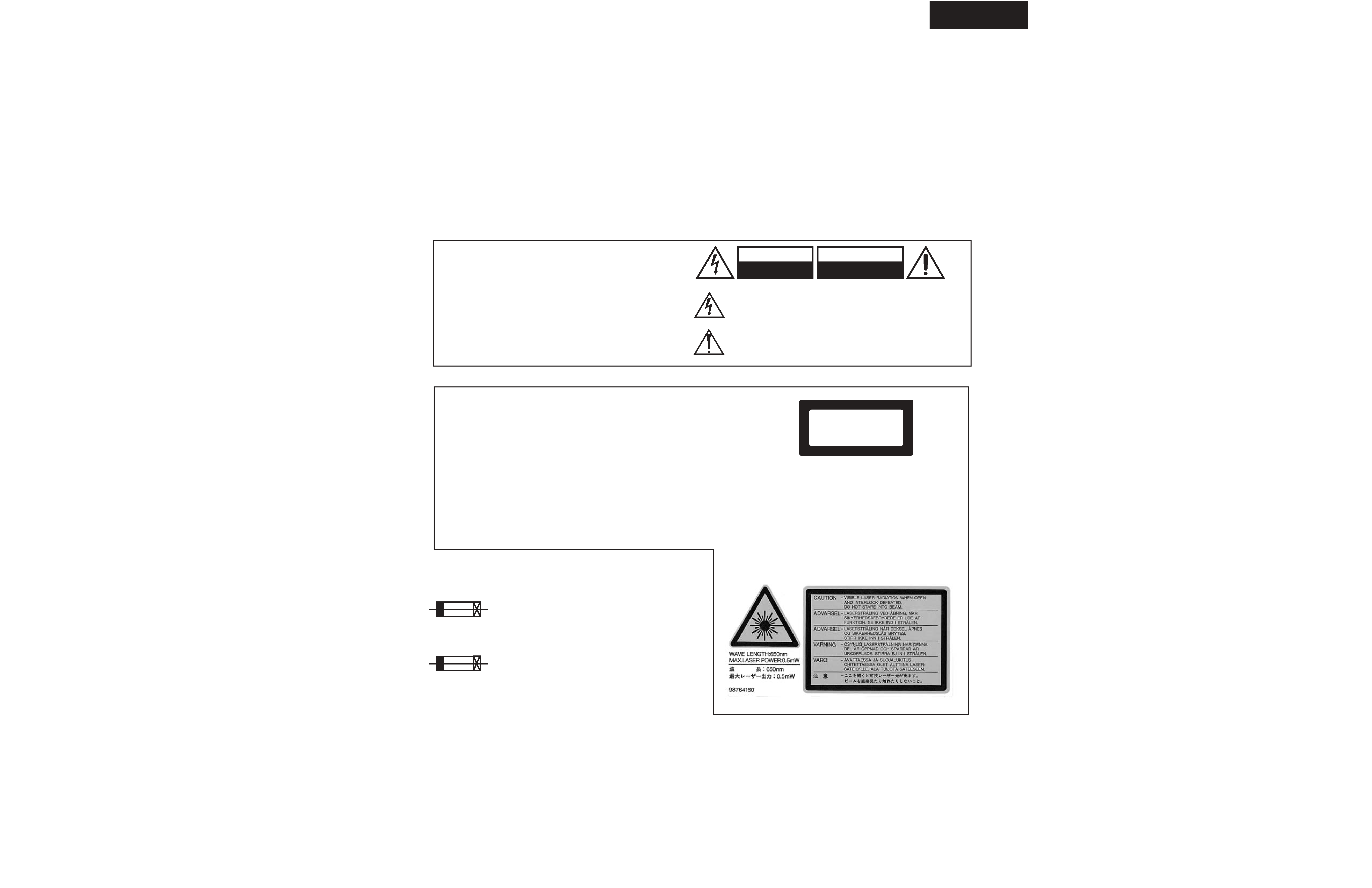
The lightning flash with arrowhead symbol, within an equilateral
triangle, is intended to alert the user to the presence of uninsulated
"dangerous voltage" within the product's enclosure that may be of
sufficient magnitude to constitute a risk of electric shock to persons.
The exclamation point within an equilateral triangle is intended to alert
the user to the presence of important operating and maintenance
(servicing) instructions in the literature accompanying the appliance.
WARNING
RISK OF ELECTRIC SHOCK
DO NOT OPEN
RISQUE DE CHOC ELECTRIQUE
NE PAS
OUVRIR
AVIS
WARNING
This unit contains a semiconductor laser system and is classified
as a "CLASS 1 LASER PRODUCT". So, to use this model
properly, read this Instruction Manual carefully. In case of any
trouble, please contact the store where you purchased the unit.
To prevent being exposed to the laser beam, do not try to open
the enclosure.
VISIBLE LASER RADIATION WHEN OPEN AND INTERLOCK
FAILED OR DEFEATED. DO NOT STARE INTO BEAM.
THIS PRODUCT UTILIZES A LASER. USE OF CONTROLS OR
ADJUSTMENTS OR PERFORMANCE OF PROCEDURES
OTHER THAN THOSE SPECIFIED HEREIN MAY RESULT IN
HAZARDOUS RADIATION EXPOSURE.
The label on the right
is applied on the rear
panel except for USA
and Canadian
models.
1. This unit is a CLASS 1 LASER PRODUCT and employs a
laser inside the cabinet.
2. To prevent the laser from being exposed, do not remove
the cover. Refer servicing to qualified personnel.
"CLASS 1 LASER
PRODUCT "
CAUTION:
CAUTION:
SERVICE PROCEDURE
1. Replacing the fuses
This symbol located near the fuse indicates that the
fuse used is show operating type, For continued protection against
fire hazard, replace with same type fuse , For fuse rating, refer to
the marking adjest to the symbol.
Ce symbole indique que le fusible utilise est e lent.
Pour une protection permanente, n'utiliser que des fusibles de meme
type. Ce demier est indique la qu le present symbol est apposre.
2. Safety-check out
(Only U.S.A. model)
After correcting the original service problem perform the
following safety check before releasing the set to the customer
Connect the insulating-resistance tester between the plug of
power supply cord and terminal GND on the back panel.
Specifications: More than 10M ohm at 500V
LASER BEAM CAUTION LABEL
CIRCUIT NO.
DESCRIPTION
PART NO.
F911, F912
2.5A-ULSE-TL250
252300
DPS-8.3
SERVICE PROCEDURES-2
Factory-shipped condition
Push button "ON" (Mechanical SW)
Press the [STOP] and [STANDBY] same time.
(Wait until FL display "No Disc") .
Push button "STANDBY".
INITIALIZING
Others
Phones level volume -------- MIN.
SURR. switch ---------------- 1
Mechanical power switch -- ON
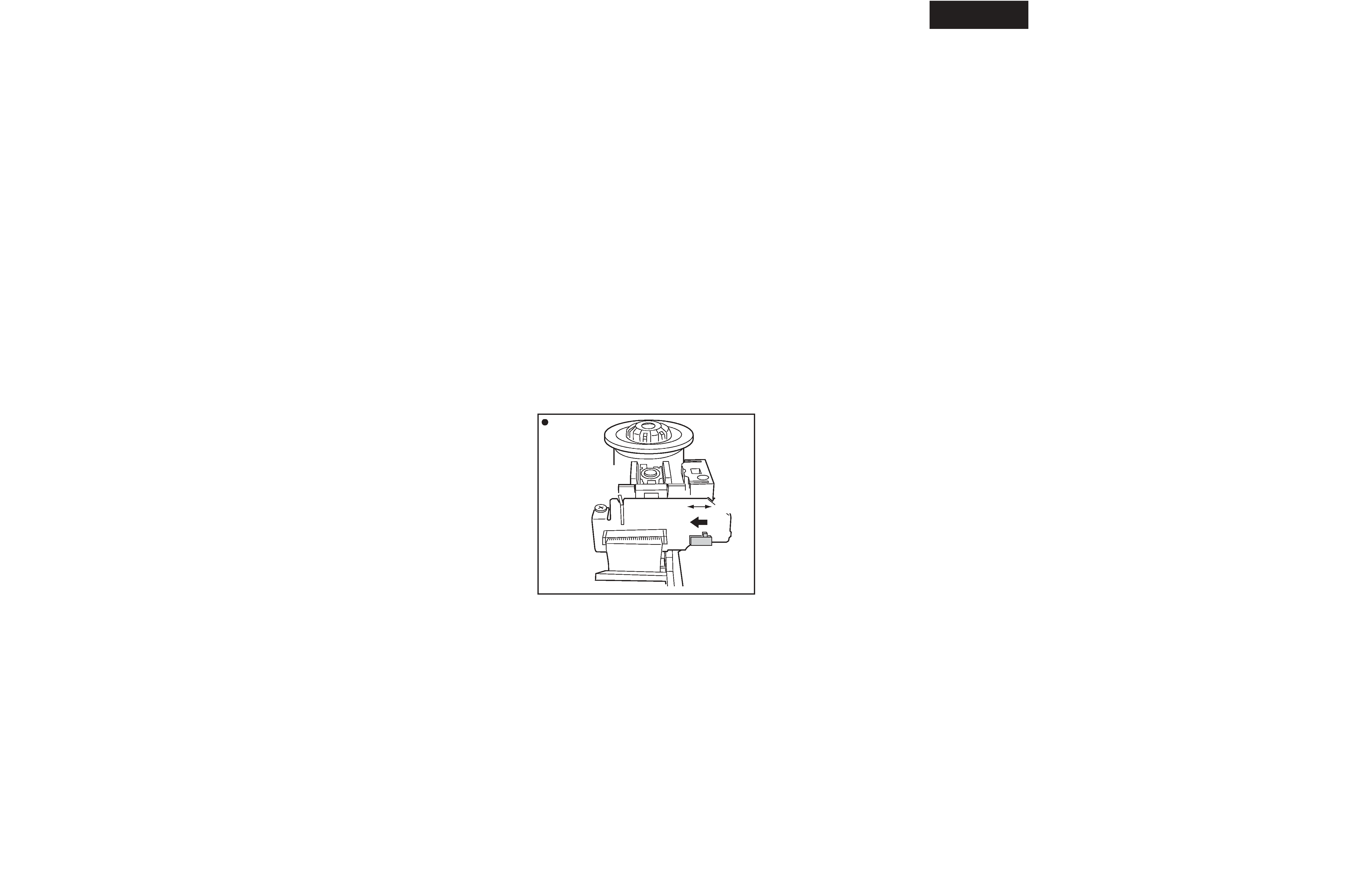
Remove the solder of Laser Diode shorting
1-1
Connect Pickup and DVD main circuit PC board by FFC (3 pcs).
1-2
Fix it with the DVD Mechanism
1-3
Remove the solder of Laser Diode shorting on Pickup.
1-4
Connect total unit of DVD Mechanism (DVD Main PCB + Mechanism) to output terminal.
Rear View
Short
DVDM Assy
Side
Short SW
Open
A29
A29
A1
A1
A3
A3
A3
A3
A7
A7
A7
A7
A11
A11
A9
A9
A9
A9
A12
A12
A12
A12
A12
A12
A38
A38
A13
A13
A13
A13
A17
A17
A21
A21
A41
A41
A203
A203
A7
A7
A7
A7
A7
A7
A7
A7
A7
A7
A7
A7
A7
A7
A33
A33
A35
A35
A35
A35
A5
A5
A5
A5
A205
A205
A23
A23
A211
A211
A209
A209
A213
A213
A215
A215
A217
A217
A221
A221
A219
A219
A219
A219
A219
A219
A219
A219
A219
A219
A121
A121
A122
A122
A123
A123
A123
A123
A62
A62
A62
A62
A62
A62
A61
A61
A62
A62
A62
A62
A62
A62
A63
A63
E702
E702
E903
E903
P1701
P1701
P1803
P1803
a
a
P701
P701
b
b
S731
S731
T901
T901
U1
U1
U2
U2
U3
U3
U4
U4
U5
U5
U6
U6
U7
U7
U8
U8
U9
U9
A7
A7
A7
A7
U10
U10
U12
U12
U13
U13
A7
A7
A7
A7
U11
U11
CN602
CN602
Z100
Z100
Z101
Z101
Z103
Z103
Z102
Z102
Z104
Z104
Z104
Z104
Z104
Z104
Z104
Z104
Z105
Z105
Z106
Z106
A7
A7
A7
A7
A7
A7
A7
A7
A7
A7
A7
A7
E701
A7
A7
E701
E701
A22
A22
A45
A45
A62
A62
P1810
A19
A19
DP
S-
8.3
A125
A125
A39
A39
A201
A201
A15
A15
A33
A33
A125
A125
A125
A125
A22
A22
CA
UT
IO
N
A207
A207
A30
A30
to Chassis
To
P1810
A22
A22
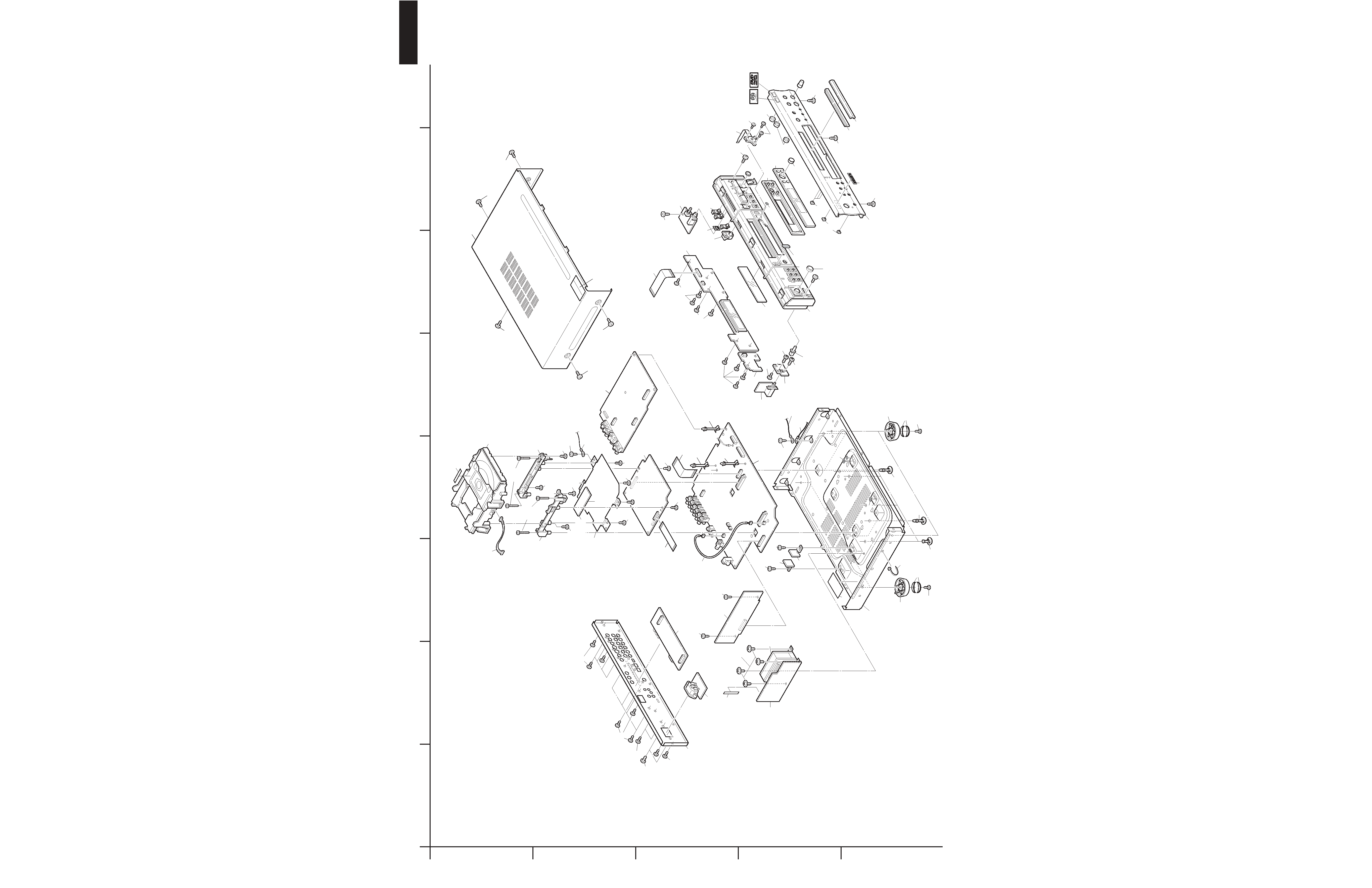
DPS-8.3
EXPLODED VIEW-1
CHASSIS
A
1
2
3
4
5
B
C
DE
FG
H
E703
E703