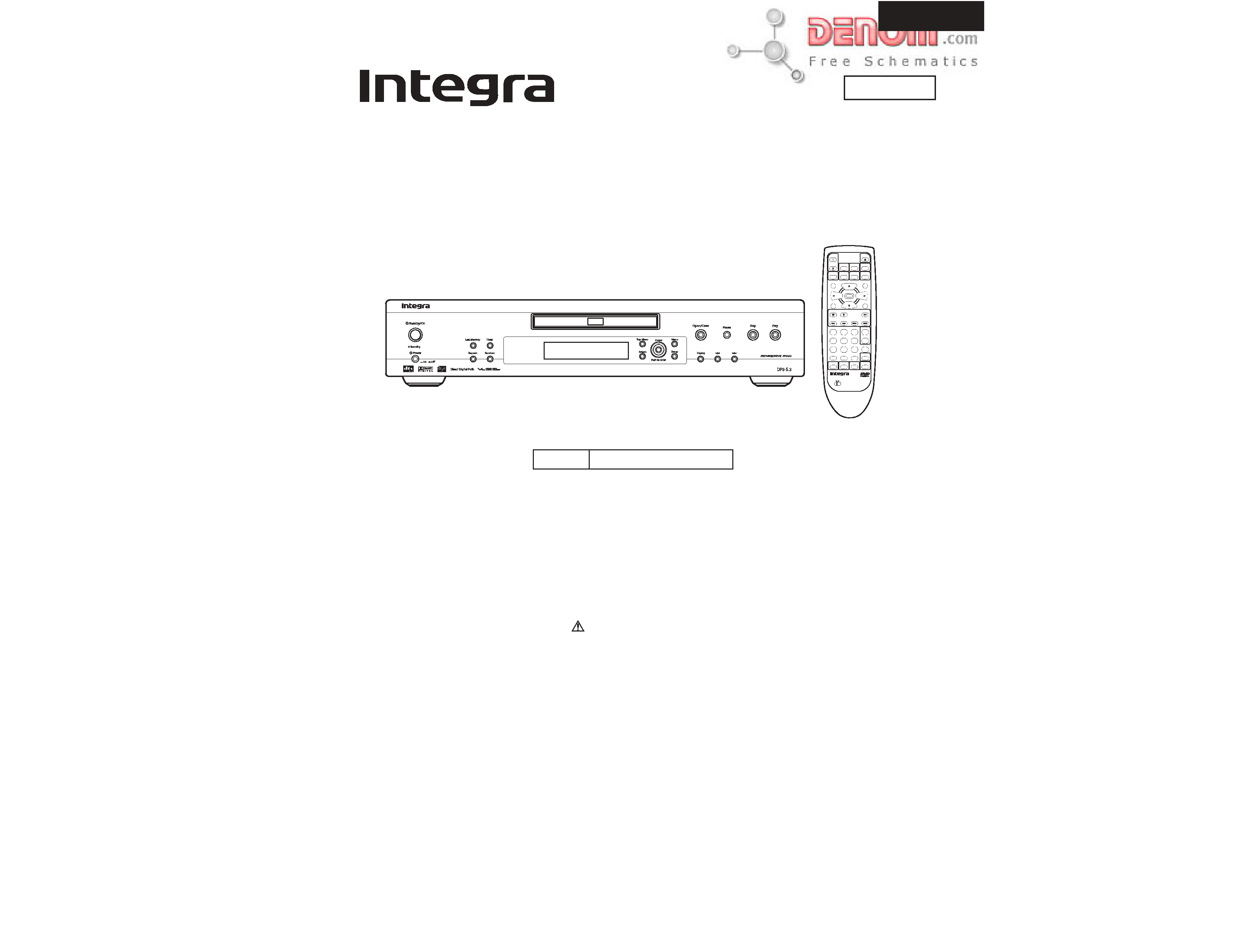
DPS-5.3
SERVICE MANUAL
SERVICE MANUAL
DVD PLAYER
Black model
MODEL DPS-5.3
120V AC, 60Hz
BMDD
Ref. No. 3726
Aug, 2002
RC-451DV
COND. M
TV
ON/STANDBY
CH +
CH -
FUNCTION M
SEARCH
23
456
78
9
1
0
+10
+
-
TV/VCR
VOL +
VOL -
TV
LAST M
DIMMER
DISPLAY
ANGLE
STANDBY
ON
AUDIO
SUBTITLE
MENU
TOP MENU
SETUP
RETURN
STOP
PAUSE
PLAY
DOWN
UP
FR
FF
CLEAR
PROGRAM
DVD
RANDOM
REPEAT
A-B
STEP/SLOW
REMOTE CONTROLLER RC-
451DV
ENTER
OPEN
/CLOSE
SAFETY-RELATED COMPONENT
WARNING!!
THE MARK
FOUND ON SOME COMPONENT
PARTS INDICATES THE CRITICAL FOR RISK OF
FIRE AND ELECTRIC SHOCK.
WHEN REPLACING, BE SURE TO USE PARTS OF
IDENTICAL DESIGNATION.
MAKE LEAKAGE-CURRENT OR RESISTANCE
MEASUREMENTS TO DETERMINE THAT EXPOSED
PARTS ARE ACCEPTABLY INSULATED FROM THE
SUPPLY CIRCUIT BEFORE RETURNING THE
APPLIANCE TO THE CUSTOMER.
www.denom.com
DPS-5.3
SPECIFICATIONS
Power supply
AC 120 V, 60 Hz
Power consumption
14 W
Power consumption (standby mode)
1.4 W
Weight
3.4 kg, 7.5 lbs.
External dimensions
435
91
312 mm (W/H/D), 17-1/8"
3-9/16"
12-5/16"
Signal system
Standard NTSC
Regional restriction code
1
Laser
Semiconductor laser, wavelength 650 nm
Frequency range (digital audio)
DVD linear sound:
48 kHz sampling 4 Hz to 22 kHz
96 kHz sampling 4 Hz to 44 kHz
Audio CD:
4 Hz to 20 kHz
Signal-to-noise ratio (digital audio)
More than 100 dB
Audio dynamic range (digital audio)
More than 96 dB
Harmonic distortion (digital audio)
Less than 0.015 %
Wow and flutter
Below measurable level (less than ±0.001 % (W.PEAK))
Operating conditions
Temperature: 5 C to 35 C (41 F to 95 F), Operation status: Horizontal
Outputs
Video output
1.0 V (p-p), 75
, negative sync., pin jack
1
S-video output
(Y) 1.0 V (p-p), 75
, negative sync., Mini DIN 4-pin
1
(C) 0.286 V (p-p), 75 ohm
Component video output
(Y) 1.0 V (p-p), 75
, negative sync., pin jack
1
(PB)/(PR) 0.7 V (p-p), 75
Audio output (digital output Optical)
-22.5 dBm
1
Audio output (digital output Coaxial)
0.5 V (p-p), 75
, pin jack
1
Audio output (analog audio)
2.0 V (rms), 470
, pin jack (L, R)
2
Audio output (Mono)
2.0 V (rms), 470
, pin jack
1
DVD Player
x
x
x
x
x
x
ohm
ohm
ohm
x
x
x
x
x
x
ohm
ohm
ohm
ohm
www.denom.com
DPS-5.3
SERVICE PROCEDURE-1
REPLACING THE FUSES
SAFETY CHECK
(Only U.S.A. model)
After correcting the original service problem perform the
following safety check before releasing the set to the customer
Connect the insulating-resistance tester between the plug of
power supply cord and terminal GND on the back panel.
Specifications: More than 10M ohm at 500V
REF.NO.
PART NO.
DESCRIPTION
F1
This symbol located near the fuse indicates that the
fuse used is show operating type, For continued protection against
fire hazard, replace with same type fuse , For fuse rating, refer to
the marking adjust to the symbol.
Ce symbole indique que le fusible utilise est e lent.
Pour une protection permanente, n'utiliser que des fusibles de meme
type. Ce demier est indique la qu le present symbol est apposre.
252252 or
1.6A-T/UL-ST2 or
252147
1.6A-TSC Fuse
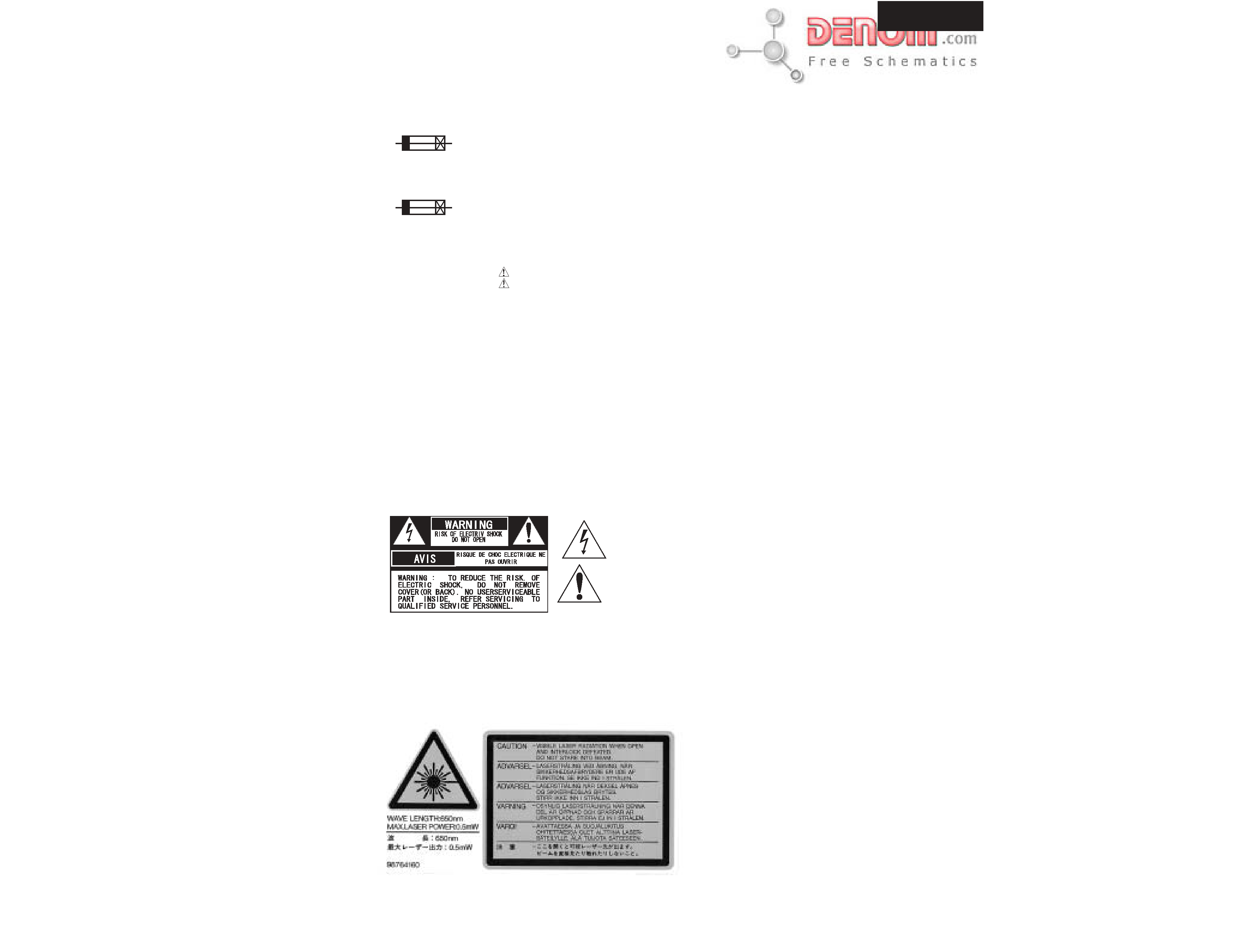
TO REDUCE THE RISK OF FIRE OR ELECTRIC SHOCK, DO NOT EXPOSE THIS APPLIANCE TO RAIN
OR MOISTURE. DANGEROUS HIGH VOLTAGES ARE PRESENT INSIDE THE ENCLOSURE. DO NOT OPEN THE
CABINET. REFER SERVICING TO QUALIFIED PERSONNEL ONLY.
TO PREVENT ELECTRIC SHOCK, MATCH WIDE BLADE OF PLUG TO WIDE SLOT, FULLY INSERT.
POUR EVITER LES CHOCS ELECTRIQUE, INTRODUIRE LA LAME LA PLUS LARGE DA LA FICHE DANS LA
BORNE CORRESPONDANTE DA LA PRISE ET POUSSER JUSQU' AU FOND.
WARNING :
CAUTION :
ATTENTION :
The lightning flash with arrowhead symbol, within an equilateral triangle, is
intended to alert the user to the presence of uninsulated "dangerous voltage"
within the product's enclosure that may be of sufficient magnitude to constitute
a risk of electric shock to persons.
The exclamation point within an equilateral triangle is intended to alert the user
to the presence of important operating and maintenance (servicing) instruction
in the literature accompanying the appliance.
LASER WARNING LABELS
www.denom.com
DPS-5.3
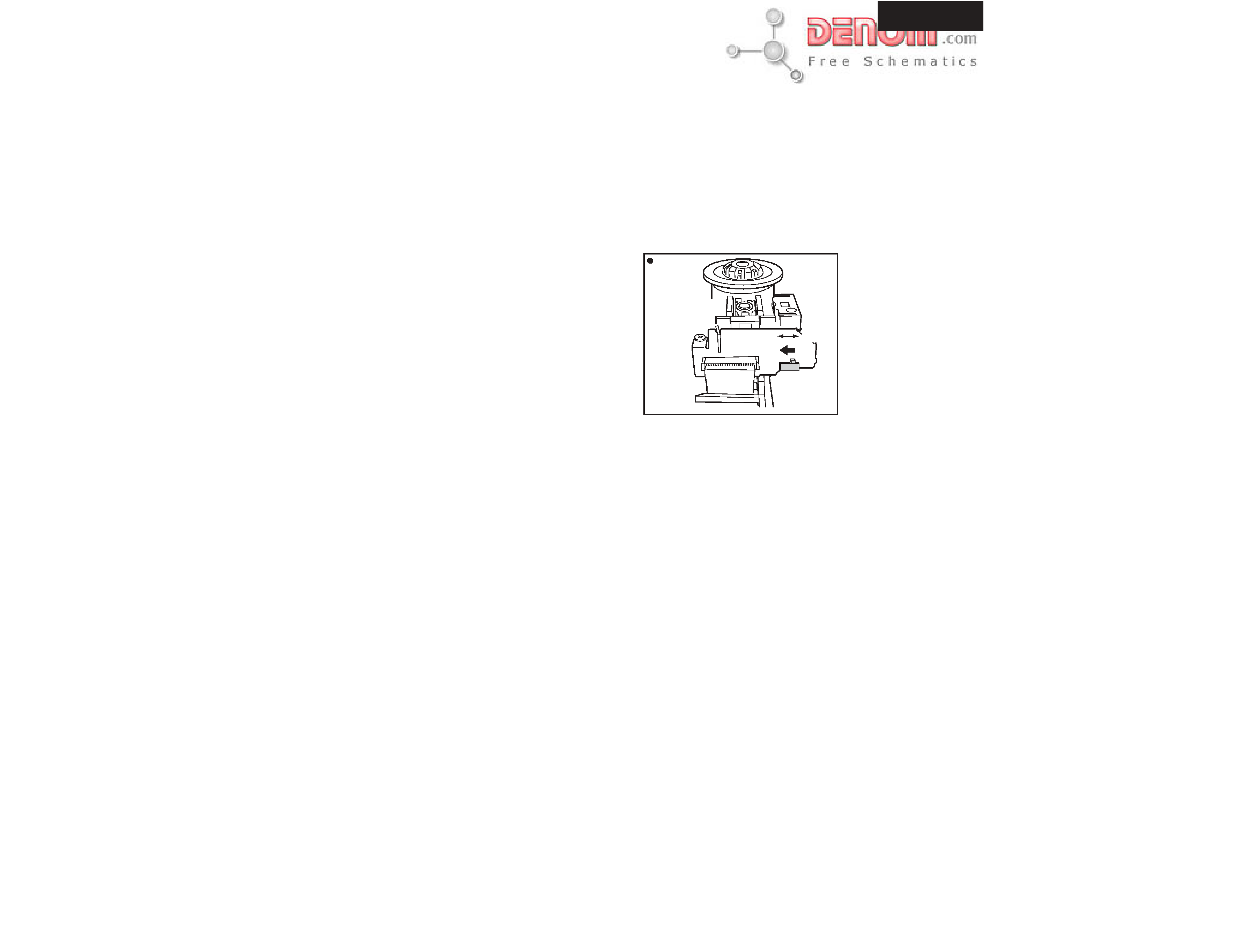
SERVICE PROCEDURE-2
1.Remove the solder of Laser Diode shorting
1-1
Connect Pickup and DVD main circuit PC board by FFC(3 pcs).
1-2
Fix it with the DVD Mecha
1-3
Remove the solder of Laser Diode shorting on Pickup.
1-4
Connect total unit of DVD Mechanism (DVD Main PCB + Mechanism) to output terminal.
PC board (NCAR7181) at CN102 and CN106
2. Key check mode
Press the [STOP] and [DISPLAY] keys at the same time .
FL display light up, and check the FL display.
To cancel this process, Please press the [STOP] and [DISPLAY] keys at the same time again.
3. Factory setting (Initial setting)
3-1 Push the power switch "ON" (Mechanical switch)
3-2 Press the [STOP] and [STANDBY ON] keys at same time, and
it waits until the display of FL tube will be the display of "No Disc" from "Loading".
Rear View
Short
DVDM Assy
Side
Short SW
Open
www.denom.com
DPS-5.3
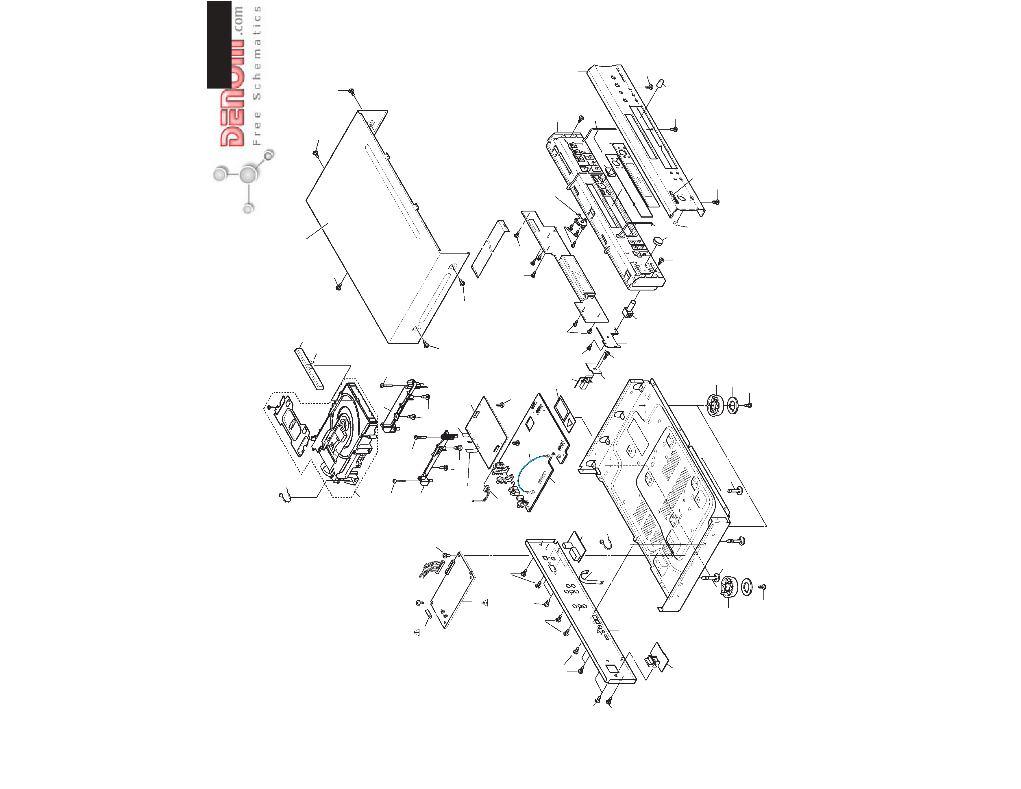
EXPLODED VIEW
A62
E751
A71
A72
To DVD
Mechanism
Z101
Z102
Z103
Z104
Z104
U1
A64
A65
A62
A19
A21
A7
03
03
A1
A3
A3
A7
E903
A61
A62
A63
A7
A5
A5
A62
A7
A11
A9
A17
A20
A7
U2
E701
A7
A7
A7
A25
A70
A66
A62
A62
E702
F1
S731
Z100
U5
U4
U6
U3
U20
A7
A24
A9
A21
A7
P351
A62
A68
A67
A69
Chassis
A62
DVD
A73
A62
A62
A62
A13
A13
A15
a
a
b
b
To DVD
Mechanism
DVP
S-5
.3
A13
E903
DI
R
EC
T
D
IG
IT
AL
PA
TH
A62
A62
U7
www.denom.com