CR-N1
SAFETY-RELATED COMPONENT
WARNING!!
COMPONENTS IDENTIFIED BY MARK
ON THE
SCHEMATIC DIAGRAM AND IN THE PARTS LIST ARE
CRITICAL FOR RISK OF FIRE AND ELECTRIC SHOCK.
REPLACE THESE COMPONENTS WITH ONKYO
PARTS WHOSE PART NUMBERS APPEAR AS SHOWN
IN THIS MANUAL.
MAKE LEAKAGE-CURRENT OR RESISTANCE
MEASUREMENTS TO DETERMINE THAT EXPOSED
PARTS ARE ACCEPTABLY INSULATED FROM THE
SUPPLY CIRCUIT BEFORE RETURNING THE
APPLIANCE TO THE CUSTOMER.
SERVICE MANUAL
CD RECEIVER
Ref. No. 3687
092001
MODEL
CR-N1
120V AC, 60Hz
230-240V AC, 50Hz
220-230V AC, 50/60Hz
(S)MDD,(S)MDT
(T)MPP,(S)MPA
(S)MGT,(S)MGR,(S)MGQ
Silver and Titanium model
RC-454S
CR-N1
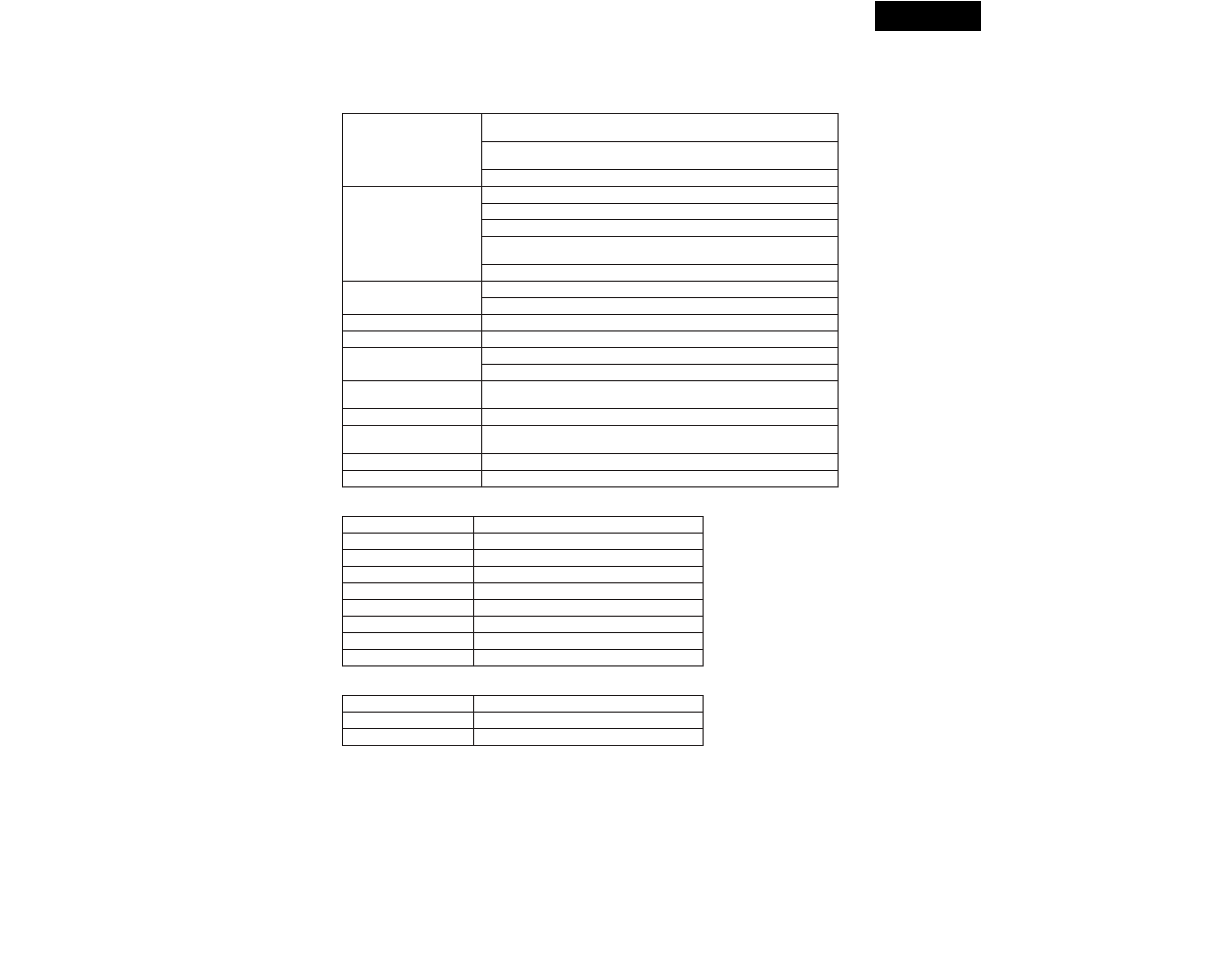
SPECIFICATIONS-1
Amplier
CD Player
USB
Power output
(U.S. & Canadian models)
2 x 6.5 watts min., RMS at 8 ohms, 50 Hz20 kHz, with no more than 0.6%
total harmonic distortion (FTC)
2 x 9.5 watts min., RMS at 4 ohms, 50 Hz20 kHz, with no more than 0.8%
total harmonic distortion (FTC)
2 x 15 watts at 4 ohms (EIAJ)
Power output
(Other models)
2 x 10 watts at 4 ohms, 1 kHz (DIN)
2 x 8.5 watts at 6 ohms, 1 kHz (DIN)
2 x 7 watts at 8 ohms, 1 kHz (DIN)
2 x 6.5 watts min., RMS at 8 ohms, 1 kHz, no more than 0.6% THD (FTC
rating)
2 x 15 watts at 4 ohms (EIAJ)
Dynamic power
2 x 15 watts at 4 ohms
2 x 9 watts at 8 ohms
Total harmonic distortion
0.4% at 5 watts output into 4 ohms, 1 kHz
IM distortion
0.4% at 5 watts output into 4 ohms, 1 kHz
Damping factor
25 at 4 ohms
50 at 8 ohms
LINE IN sensitivity and
impedance
500 mV, 47kohms
Frequency response
10 Hz20 kHz, +3/3 dB
Acoustic presence
1: +6.0 dB at 80 Hz
2: +10.0 dB at 80 Hz
Signal to noise ratio
95 dB (IHF-A)
Muting
50 dB
Signal readout system
Optical non-contact
Reading rotation
Approx. 500200 rpm (constant linear velocity)
Linear velocity
1.21.4 m/s
Error correction system
Cross interleave Reed Solomon code
D/A converter
1 bit
Digital lter
352.8 kHz, 8-times oversampling
Number of channels
2 (stereo)
Frequency response
5 Hz20 kHz
Wow & utter
Below threshold of measurability
Connection method
USB (Universal Serial Bus) Ver 1.1
Sampling rate (input)
32/44.1/48 kHz compatible
Frequency response
5 Hz20 kHz
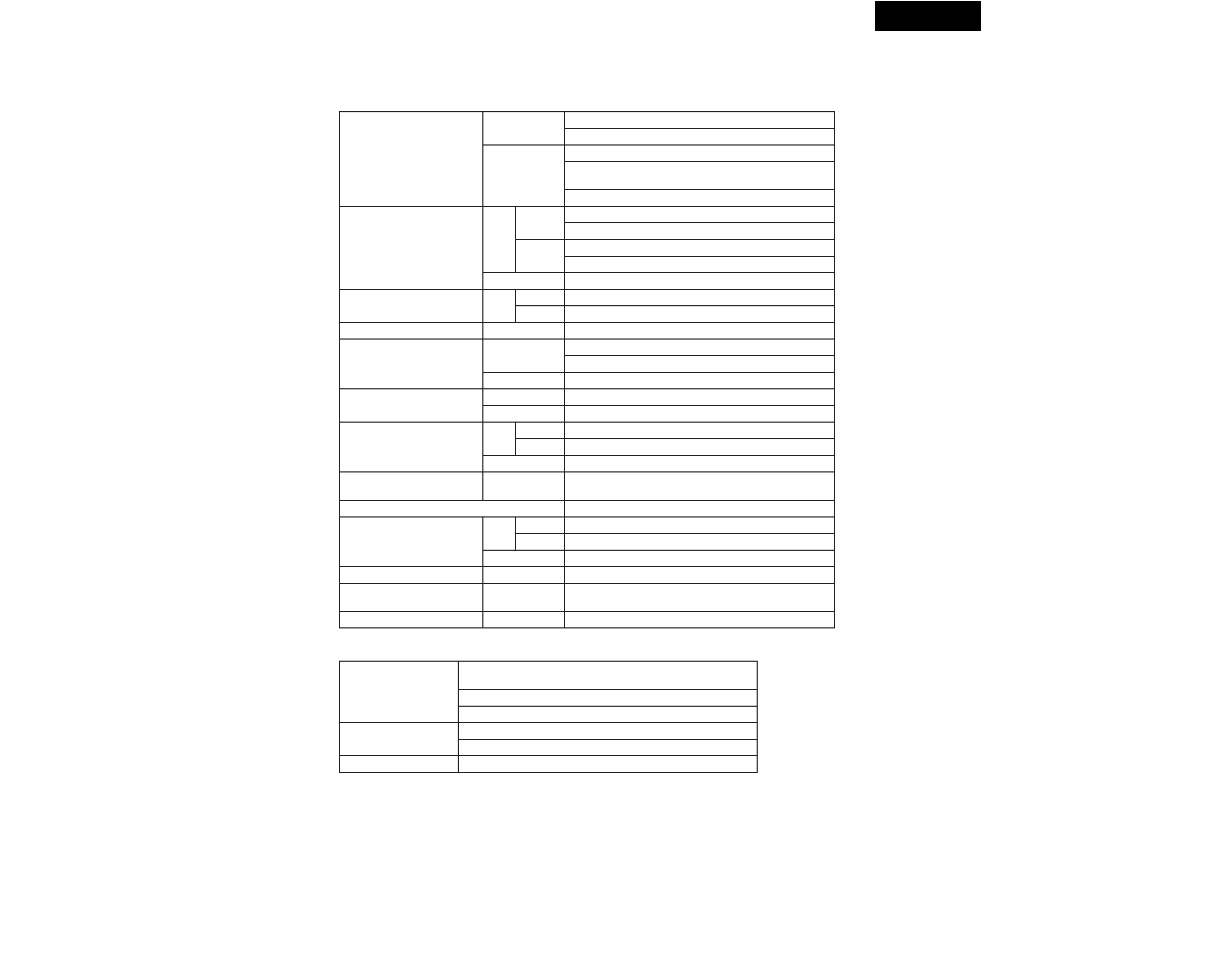
CR-N1
SPECIFICATIONS-2
General
Specications and features are subject to change without notice.
Power supply and voltage specications depend on where the unit is purchased.
Tuning range
FM
87.9107.9 MHz (200 kHz steps) (U.S. & Canadian model)
87.5108.00 MHz (50 kHz steps) (Other area models)
AM
5301710 kHz (10 kHz steps) (U.S. & Canadian model)
5221611 kHz (9 kHz steps) (European & Australian
models)
5311602 kHz (9 kHz steps) (Asian models)
Usable sensitivity
FM
Mono
11.2 dBf, 1.0 µV (75 ohms IHF)
11.2 dBf, 0.9 µV (75 ohms DIN)
Stereo
17.2 dBf, 2.0 µV (75 ohms IHF)
17.2 dBf, 23.0 µV (75 ohms DIN)
AM
30 µV
50 dB quieting sensitivity
FM
Mono
17.2 dBf, 2.0 µV (75 ohms)
Stereo
37.2 dBf, 20.0 µV (75 ohms)
Capture ratio
FM
2.0 dB
Image rejection ratio
FM
40 dB (U.S. & Canadian model)
85 dB (Other area models)
AM
40 dB
IF rejection ratio
FM
90 dB
AM
40 dB
Signal to noise ratio
FM
Mono
73 dB, IHF
Stereo
67 dB, IHF
AM
40 dB
Selectivity
FM
50 dB DIN
(±300 kHz at 40 kHz deviation)
AM suppression ratio
50 dB
Harmonic distortion
FM
Mono
0.2%
Stereo
0.3%
AM
0.7%
Frequency response
FM
30 Hz15.0 kHz (±1.5 dB)
Stereo separation
FM
35 dB at 1 kHz
25 dB at 100 Hz10.0 kHz
Stereo threshold
FM
17.2 dBf, 2.0 µV (75 ohms)
Power supply
AC 120 V, 60 Hz, 39 W (U.S. & Canadian model, some Asian
models)
AC 230 V, 50 Hz, 32 W (European model)
AC 220 V, 50/60 Hz, 32 W (Other area models)
Dimensions (W x H x D)
203 x 270 x 234 mm
8" x 10-5/8" x 9-3/16"
Weight
4.2 kg (9.3 lbs)
Tuner
CR-N1
PROTECTION OF EYES FROM LASER BEAM DURING SERVICING
This set employs a laser. Therefore, be sure to follow carefully
the instructions below when servicing.
WARNING!!
SERVICE WARNING : DO NOT APPROACH THE
LASER EXIT WITH THE EYE TOO CLOSELY.
IN CASE IT IS NECESSARY TO CONFIRM LASER
BEAM EMISSION, BE SURE TO OBSERVE FROM
A DISTANCE OF MORE THAN 30cm FROM THE
SURFACE OF THE OBJECTIVE LENS ON THE
OPTICAL PICK-UP BLOCK.
Laser Diode Properties
Material: GaAS/GaALAs
Wavelength: 790nm
Emission Duration: continuous
Laser output: max. 0.5mW*
*This output is the value measured at a distance about 1.8mm
from the objective lens surface on the Optical Pick-up Block.
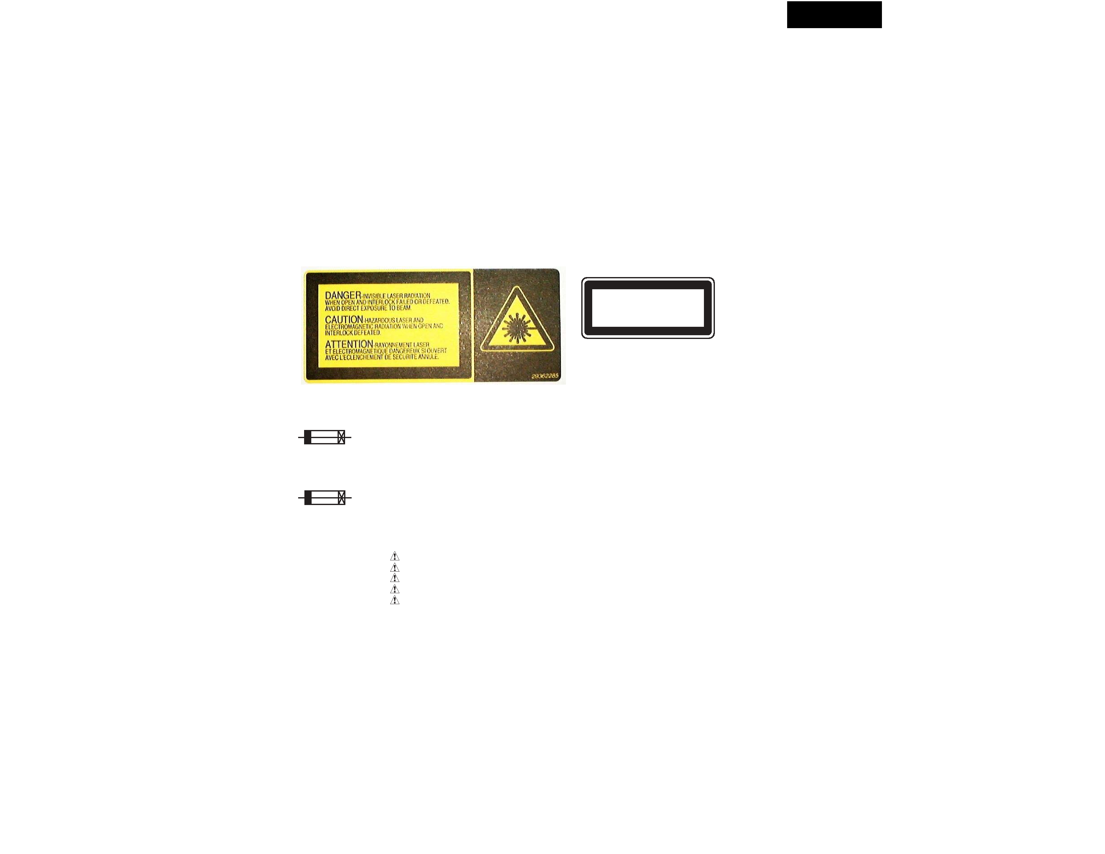
LASER WARNING LABEL
The label shown below are affixed.
1. Warning label
2. Class 1 label
"CLASS 1 LASER
PRODUCT"
LUOKAN 1
LASERLAITE
KLASS 1
LASER APPARAT
SERVICE PROCEDURE
1. Replacing the fuses
2. Safety-check out
(Only U.S.A. model)
After correcting the original service problem perform the
follwing safety check before releasing the set to the customer
Connect the insulating-resistance tester between the plug of
power supply cord and terminal GND on the back panel.
Specifications: More than 10Mohm at 500V
REF.NO. PART NO.
DESCRIPTION
This symbol located near the fuse indicates that the
fuse used is show operating type, For continued protection against
fire hazard, replace with same type fuse , For fuse rating, refer to
the marking adjest to the symbol.
1. Press and the hold down the VOLUME DOWN button ,
then press the DISPLAY button.
3. To initialize the unit
Ce symbole indique que le fusible utilise est e lent.
Pour une protection permanente, n'utiliser que des fusibles de meme
type. Ce demier est indique la qu le present symbol est apposre.
SERVICE PROCEDURES
5. Changing the AM band step
F901
252083 or
0.4A-SE-EAWK
252233 or
400MA-SE-TL250V or
252267
400MA-SE-TL250V <PP,GT,PA,GQ,GR>
252157 or
1.25A-UL/T-237 or
252251
1.25A-T/UL-ST2, Fuse <DD,DT>
NOTE:
<DD> : USA and Canadian model only
<PP> : European model only
<PA> : Australian model only
<DT> : Taiwanese model only
<GT> : Asian model only
<GR> : Chinese model only
<GQ> : Hong kong model only
2. After " All lighting " is displayed, the preset memory and each
mode stored in the memory, are initialized and will return to the
factory settings.
3. Press the STANDBY/ON button.
4. Unplug the AC plug from the wall outlet.
Refer to "SCHEMATIC DIAGRAM-1"
4. Notes at the connecting the measuring instrument
to the unit.
The power amplifier circuit of this unit is BTL system.
Therefore, in case check the output of speaker terminal,
take care not to connect the ground of the unit with the
minus terminal of speaker.
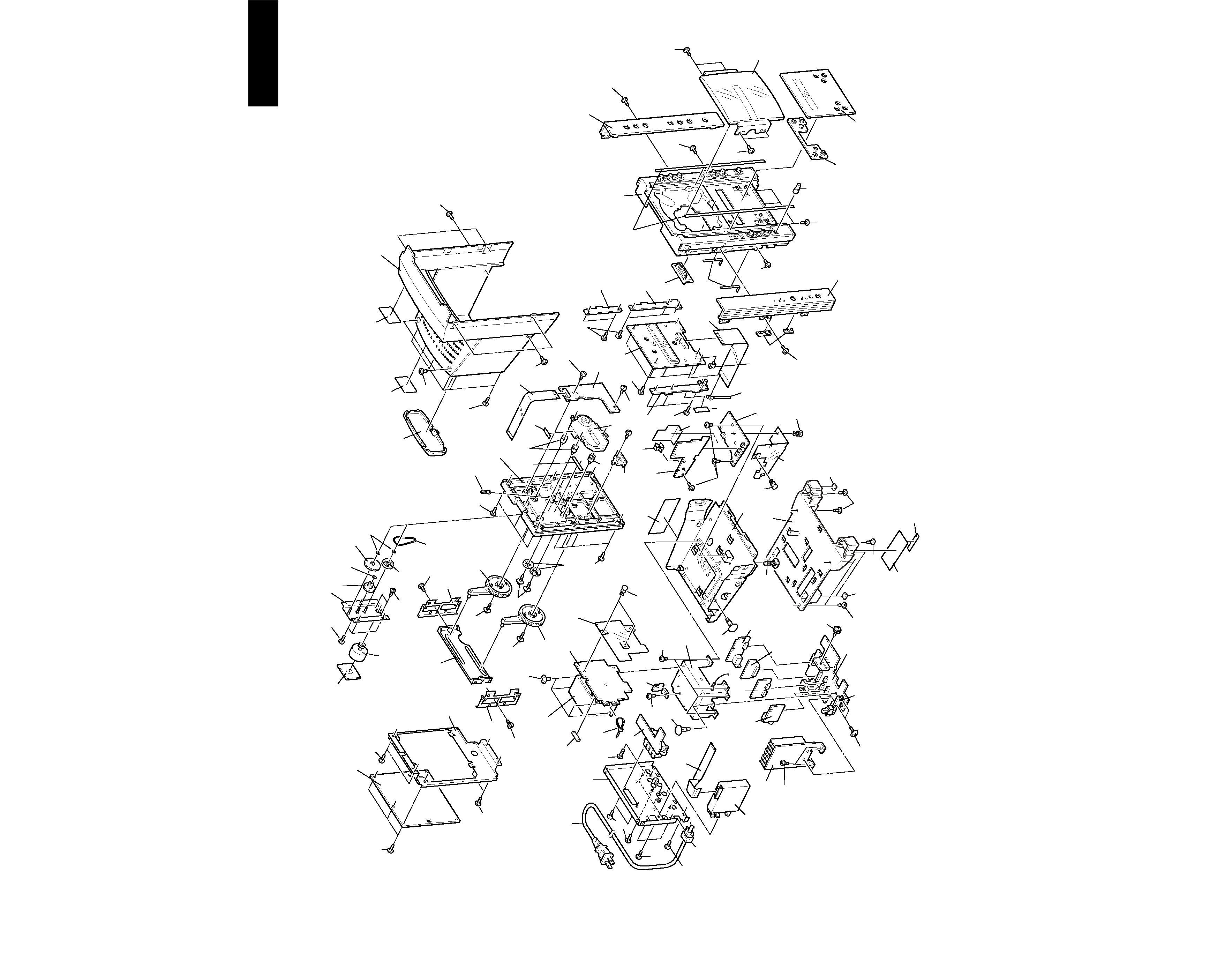
CR-N1
CHASSIS EXPLODED VIEW
37
35
U7
U8
U9
U6
19
39
Q501
U13
39
37
23
79
80
37
37
23
21
17
49
49
47
37
U15
M2
P701
37
73
37
37
53
9
11
63
65
37
65
37
74
1
3
6
75
U5
U4
M2
U2
E702
U18
P908
U17
M5
M2
U10
P102
M8
M6
M3
M6
16
37
16
59
81
16
54
U11
M11
M19
M12
M10
M18
M17
M18
M14
M24
M23
M24
M24
M23
M22
M27
M2
M7
M1
M2
78
13
U20
P551
29
U19
37
37
27
49
43
U14
T901
33
F901
86
84
U16
71
P901
16
77
16
41
M33
U1
M19
M32
M19
M29
M29
M28
M16
7
5
5
U3
82
M15
M28
85
E703
4