C-701A
SAFETY-RELATED COMPONENT
WARNING!!
COMPONENTS IDENTIFIED BY MARK
ON THE
SCHEMATIC DIAGRAM AND IN THE PARTS LIST ARE
CRITICAL FOR RISK OF FIRE AND ELECTRIC SHOCK.
REPLACE THESE COMPONENTS WITH ONKYO
PARTS WHOSE PART NUMBERS APPEAR AS SHOWN
IN THIS MANUAL.
MAKE LEAKAGE-CURRENT OR RESISTANCE
MEASUREMENTS TO DETERMINE THAT EXPOSED
PARTS ARE ACCEPTABLY INSULATED FROM THE
SUPPLY CIRCUIT BEFORE RETURNING THE
APPLIANCE TO THE CUSTOMER.
SERVICE MANUAL
SERVICE MANUAL
Silver model
230-240V AC, 50Hz
120V AC, 60Hz
220-230V AC, 50/60Hz
SMPP,SMGT
SMDT
SMGR
Ref. No. 3696
092001
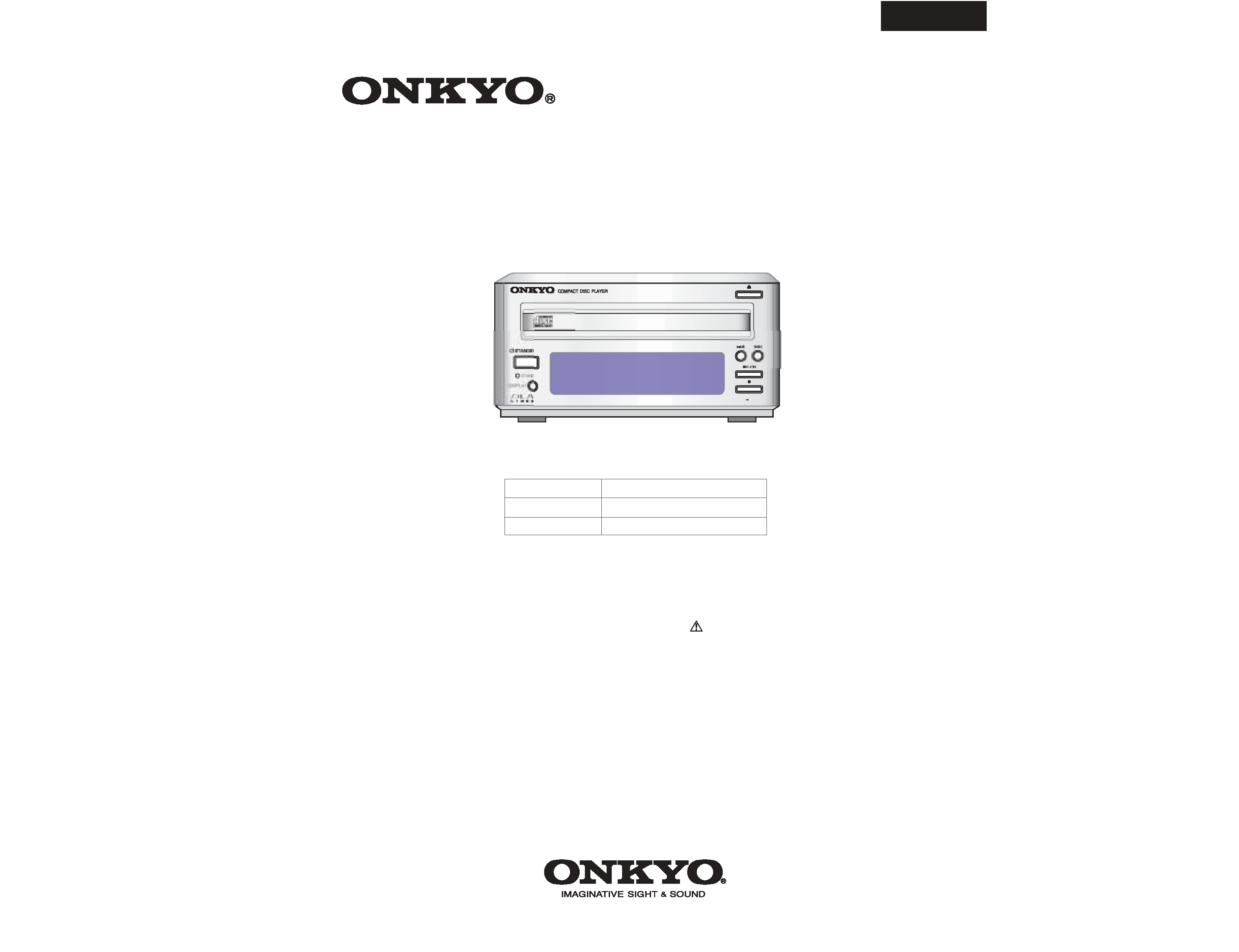
Compact Disc Player
/ ON
BY
C
701A
C-701A
MODEL
C-701A
SERVICE PROCEDURES 1
PROTECTION OF EYES FROM LASER BEAM DURING SERVICING
This set employs a laser. Therefore, be sure to follow
carefully the instructions below when servicing.
WARNING!!
SERVICE WARNING : DO NOT APPROACH THE
LASER EXIT WITH THE EYE TOO CLOSELY.
IN CASE IT IS NECESSARY TO CONFIRM LASER
BEAM EMISSION, BE SURE TO OBSERVE FROM
A DISTANCE OF MORE THAN 30cm FROM THE
SURFACE OF THE OBJECTIVE LENS ON THE
OPTICAL PICKUP BLOCK.
Laser Diode Properties
Material: GaAS/GaAlAs
Wavelength: 780nm
Laser output: max. 0.5mW*
Emission Duration: continuous
*This output is the value measured at a distance about 1.8mm
from the objective lens surface on the Optical Pickup Block.
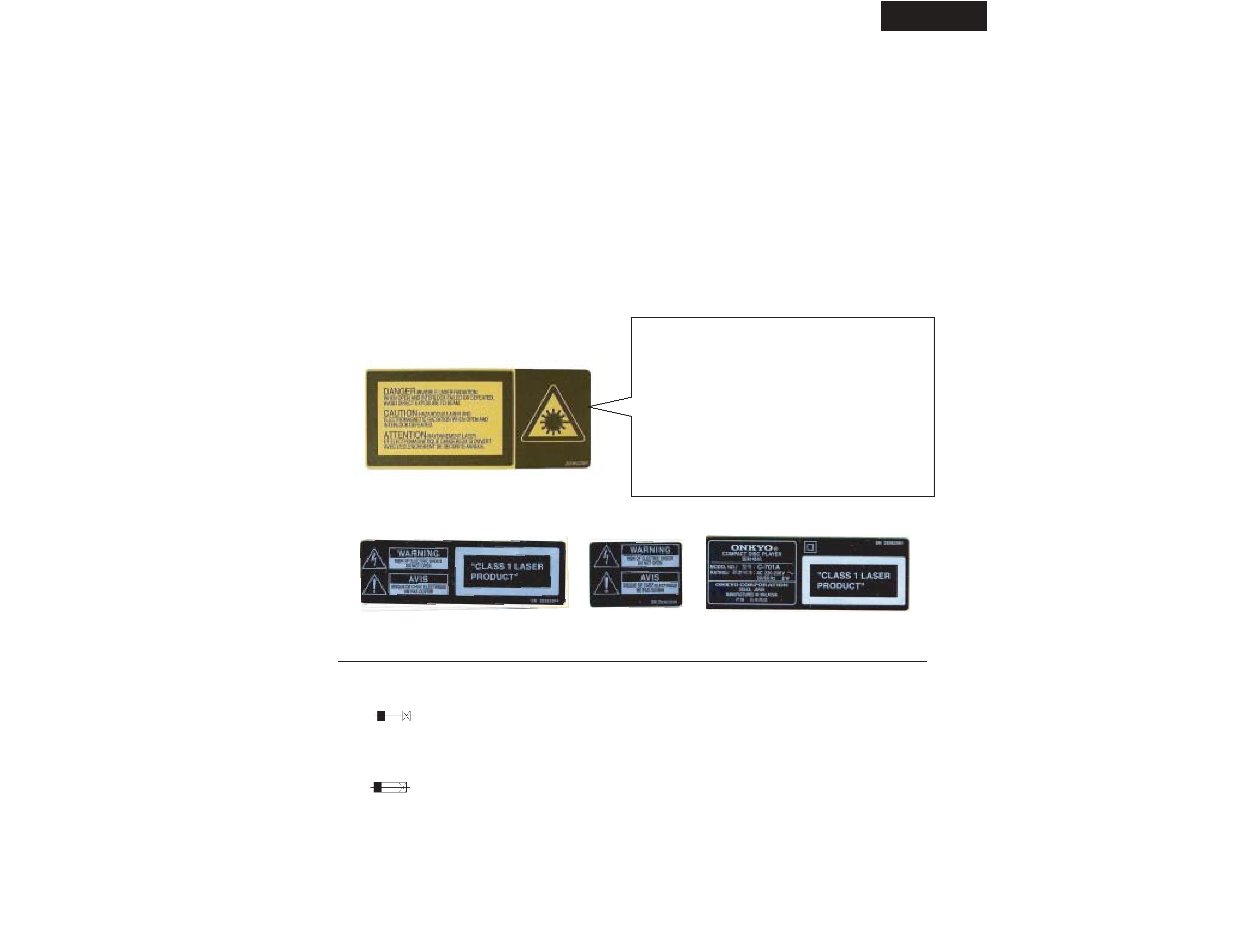
LASER WARNING LABEL
The labels shown below are affixed.
DANGER:
INVISIBLE LASER RADIATION WHEN OPEN AND
INTERLOCK FAILED OR DEFEATED. AVOID DIRECT
EXPOSURE TO BEAM.
CAUTION:
HAZARDOUS LASER AND ELECTROMAGNETIC
RADIATION WHEN OPEN AND INTERLOCK DEFEATED.
ATTENTION:
RAYONNEMENT LASER ET ELECTROMAGNETIQUE
DANGEREUX SI OUVERT AVEC L'ECLENCHEMENT
DE SECURITE ANNULE.
2. Class 1 label
MPP/MGT
MDT
MGR
2.Safety check out
After correcting the original service problem perform
the following safety check before releasing the set
to the customer.
Connect the insulating-resistance tester between the
plug of power supply cord and terminal GND on the
back panel.
Specifications: More than 10 M ohm at 500V.
(Only U.S.A. model)
E LENT. POUR UNE PROTECTION PERMANENTE,N'UTILISER
CE SYMBOLE INDIQUE QUE LE FUSIBLE UTLISE EST
INDIQUE LA QU LE PRESENT SYMBOL EST APPOSE.
QUE DES FUSIBLES DE MEME TYPE. CE DARNIER EST
RATING REFER TO THE MARKING ADJACENT TO THE SYMBOL
FOR CONTINUED PROTECTION AGAINST FIRE
HAZARD,REPLACE WITH SAME TYPE FUSE. FOR FUSE
THIS SYMBOL LOCATED NEAR THE FUSE INDICATES
THAT THE FUSE USED IS SLOW OPERATING TYPE
1. Replacing the fuse
REF. NO.
PART NO.
DESCRIPTION
F901
252074
2A-SE-EAK
<MPP,MGR,MGT>
1. Warning label
C-701A
NOTE
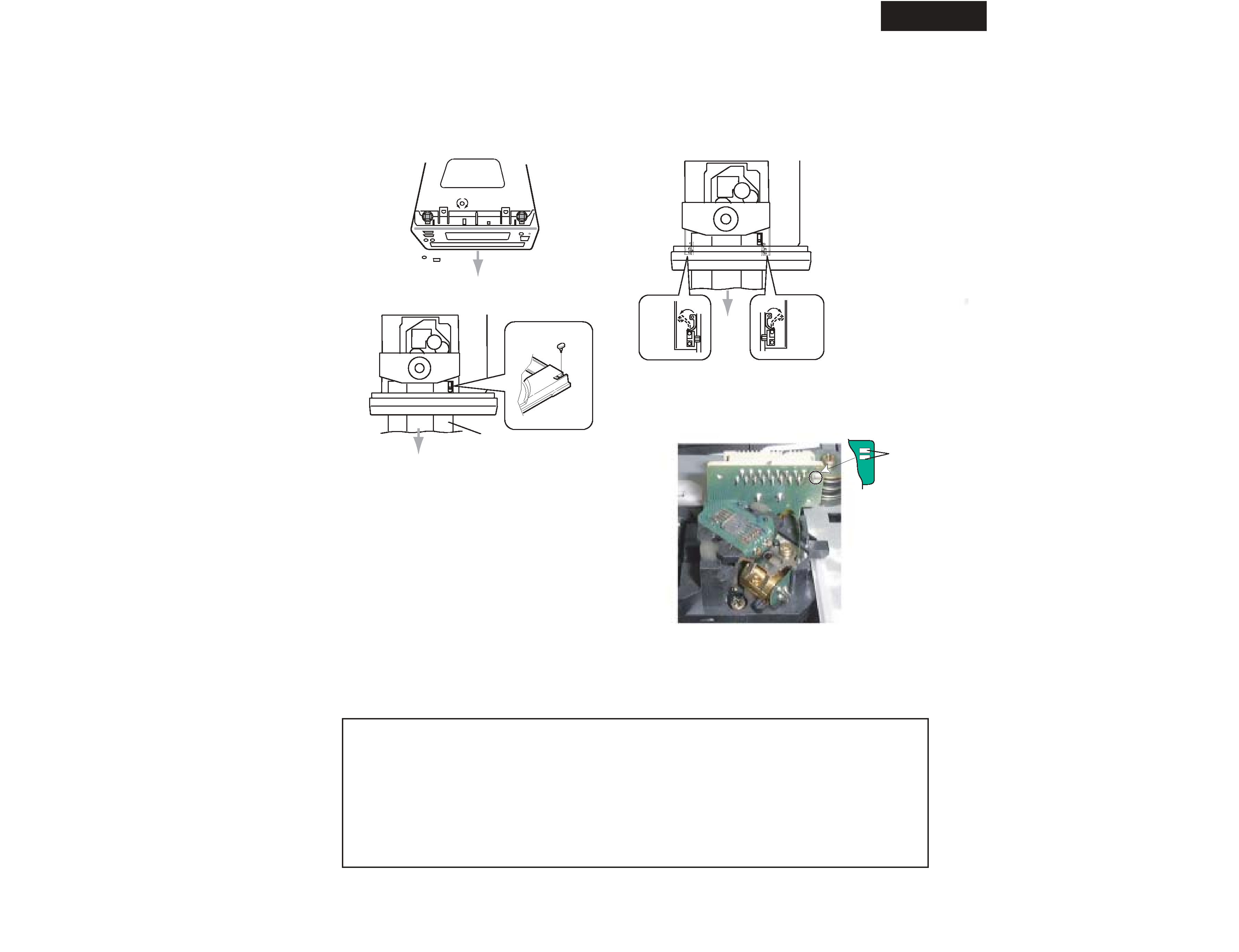
1. Removement of tray
1. Remove the top cover
2. Turn the locked screw to the clockwise to release the lock of gear.
(Refer to fig-1)
Lock
Unlock
Bottom side
Fig-1
3. Pull out the tray.
4. Remove the stopper. (Refer to fig-2)
5. Press the tray stopper to the arrow mark direction and remove
the tray ass'y. (Refer to fig-3)
Fig-2
Stopper
Tray
Fig-3
Tray
stopper
Tray
stopper
Front
Front
Front
SERVICE PROCEDURES 2
2. Replacement of optical pick-up
The laser diode in the optical pickup block is so sensitive to static
electricity, surge current and etc. that the components are liable to
be broken down or its reliability remarkably deteriorated.
During repair, carefully take the following precautions.
1. Solder the LD short terminal on mechanism.
2. Disconnect the flexible flat cable P101.
3. Replace the optical pickup.
4. Connect the flexible flat cable P101.
5. Unsolder the LD short terminal on mechanism.
Pick up short land
LD Short
Terminal
1. Ground for the work-desk.
Place a conductive sheet such as a sheet of copper
(with impedance lower than 10Mohm) on the work-
desk and place the set on the conductive sheet so that
the chassis can be grounded.
2. Grounding for the test equipments and tools.
Test equipments and toolings should be grounded in
order that their ground level is the same the ground of
the power source.
3. Grounding for the human body.
Be sure to put on a wrist-strap for grounding whose
other end is grounded.
Be particularly careful when the workers wear
synthetic fiber clothes, or air is dry.
4. Select a soldering iron that permits no leakage and
have the tip of the iron well-grounded.
5. Do not check the laser diode terminals with the
probe of a circuit tester or oscilloscope.

C-701A
SPECIFICATIONS
Signal readout system : Optical non-contact
Reading rotation : About 500 - 200 r.p.m.
(constant linear velocity)
Linear velocity : 1.2 -1.4 m/s
Error correction system :
Cross Interleave Reed Solomon code
D/A converter : 1 bit D/A converter
Sampling frequency : 352.8 kHz
(Eight-times oversampling)
Number of channels : 2 (stereo)
Frequency response : 5 Hz - 20 kHz
Total harmonic distortion : 0.009% (at 1 kHz)
Dynamic range : 92 dB
Signal to noise ratio : 80 dB
Channel separation : 80 dB (at 1 kHz)
Wow and Flutter :
Below threshold of measurability
Output level : 2 volts r.m.s.
Power consumption :
AC 230-240 V, 50 Hz model : 8 watts
AC 220-230V, 50Hz/60Hz : 8 watts
AC 120 V, 60 Hz model : 9 watts
Power supply rating :
AC 230-240 V, 50 Hz
AC 220-230V, 50Hz/60Hz
AC 120 V, 60 Hz
Dimensions (W x H x D) :
155 x 76 x 283.5 mm <MGR> model
6-1/8" x 3" x 11-3/16"
155 x 76 x 281.5 mm <MPP/MGT> model
6-1/8" x 3" x 11-1/16"
Weight : 2.0 kg, 4.4 lbs.
Specifications and external appearance are subject to
change without notice because of product improvements.
<MPP>: European model only
<MDT>: Taiwanese model only
<MGT>: Asian model only
<MGR>: Chinese model only
CONFIRM THE FL DISPLAY
1) Press the STANDBY key ON.
2) Press and hold down the STOP button, then
press the UP
button.
After " 010702A" (Microprocessor version) is
displayed. All the segments of FL tube light up
after 1 seconds.
3) Press the STOP key . ("NO KEY" is displayed)
4) Confirm the each key.
5) Press the STANDBY key to release the test mode.
155 x 76 x 277.5 mm <MDT> model
C-701A
A1
A5
A9
A9
A9
A9
A9
A9
A9
A11
A13
A15
A17
A18
A20
A23
A24
A25
A101
A102
A201
A203
A107
A204
A210
A215
A216
A216
A216
A216
A219
A219
A219
A219
A108
<MPP>only
A221
A301
A705
F901
P701
P101
P701
P901
T901
U1
U2
U3
U4
U5
U6
U7
Z01
J904
A103
A103
<MGR>only
A9
P701
A27
A105
A104
<MGR>only
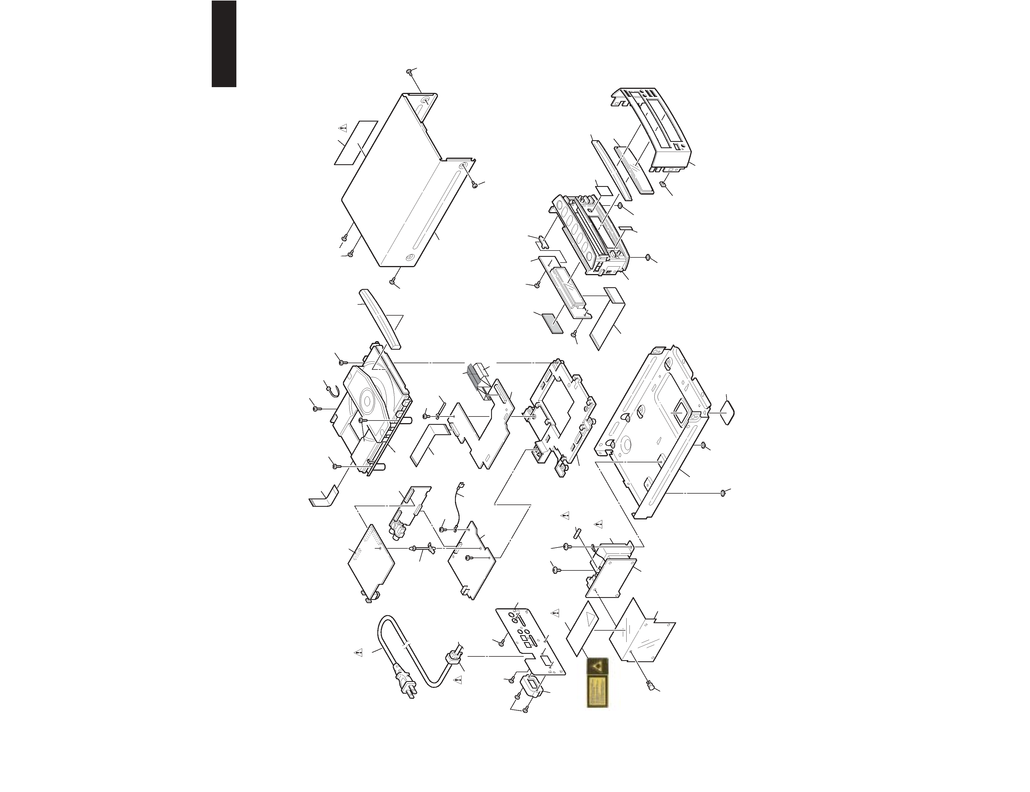
EXPLODED VIEW